Hook On Aluminum Panel Engineering From Return Edge Tolerances to Wind Load Performance
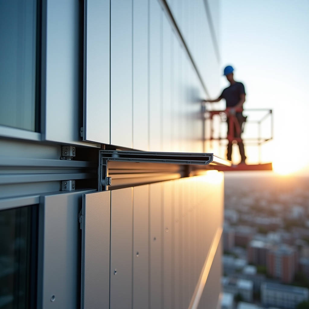
Specifying a rainscreen system means balancing speed of erection, long-term structural performance, and thermal movement accommodation. The Hook On Aluminum Panel method addresses all three by replacing face-fastened perforation with a concealed interlock that hangs solid aluminium sheets onto a continuous carrier rail. Contractors who have struggled with wind-lock extrusions or exposed fastener heads on high-visibility facades often move toward hook-on detailing because it eliminates the single largest source of callbacks on metal cladding jobs: fastener staining and gasket degradation around every penetration point. A properly engineered Hook On Aluminum Panel assembly transfers dead load and wind suction through the panel's folded return edge into the J-profile carrier, leaving the visible face completely uninterrupted. This article examines the structural logic behind that connection, the fabrication tolerances that make or break a watertight install, and the cost implications of choosing hook-on over routed-and-clipped or face-secured alternatives.
How the Hook-On Connection Actually Works
The mechanical principle is straightforward. Each solid aluminium panel—typically 2.5 mm or 3.0 mm thick 5052 or 3003 alloy—has a top return edge folded rearward during fabrication. A continuous J-shaped aluminium carrier rail is anchored to the vertical subframe at predetermined horizontal girts. The panel's folded return hooks over the upturned leg of the J-rail, and gravity seats it. The bottom edge of the panel either rests on the panel below or engages a secondary clip that prevents wind-induced disengagement.
What distinguishes this from a simple hanging system is the dimensional relationship between the panel return and the carrier. The return must be deep enough that wind suction cannot lift the panel off the rail. A typical detail calls for a 20 mm to 25 mm return depth, with the carrier leg extending at least 15 mm into that pocket. That leaves a 5 mm to 10 mm safety margin for thermal expansion and installation tolerance. If the return is too shallow—say 12 mm—the panel can disengage under negative pressure events that exceed 2.0 kPa. Engineers specifying Hook On Aluminum Panel systems in hurricane-prone regions should require a minimum 22 mm return depth and verify it on shop drawings before fabrication begins.
Fabrication Tolerances That Determine Field Performance
Hook-on cladding is unforgiving of fabrication error. A face-fastened panel can absorb 3 mm of misalignment because the fastener slot allows adjustment. A hook-on panel has no such forgiveness. The relationship between the folded return edge and the carrier rail is fixed once the panel leaves the CNC folder.
Three tolerance bands matter most:
- Return edge flatness: The folded return must be parallel to the panel face within 0.5 mm across its length. A bowed return creates point contact with the carrier instead of full bearing, concentrating stress and inviting fatigue cracking at the fold line.
- Panel squareness: Diagonal measurements should not differ by more than 1.5 mm. An out-of-square panel forces the installer to twist it onto the carrier, which can permanently deform the return edge or scrape coating off the carrier rail.
- Carrier rail straightness: Extruded aluminium J-rails in 6 m lengths must be straight within 2 mm over the full span. Waviness in the carrier translates directly into waviness in the installed facade because the panel cannot be independently shimmed.
Fabricators running CNC press brakes with automatic back-gauging consistently hold these tolerances. Shops relying on manual folding should be audited before awarding a hook-on package. The cost of reworking 200 panels that do not seat properly on site far exceeds any savings from a lower fabrication quote.
Wind Load Performance and Pressure Equalization
One persistent misconception holds that hook-on systems are inherently weaker than face-fastened ones. The data does not support this. A 3.0 mm solid aluminium panel with a 22 mm return edge hooked onto a continuous 6063-T6 aluminium J-rail can resist wind loads exceeding 3.5 kPa when the rail spacing is designed correctly. The limiting factor is usually not the hook connection itself but the rail-to-subframe fastening and the subframe-to-structure anchors.
The more nuanced engineering question is pressure equalization. A Hook On Aluminum Panel rainscreen creates a cavity behind the panel face. If that cavity is not properly compartmentalized and ventilated, wind-driven rain can pressurize the cavity and force moisture past the horizontal joints. The correct detailing approach follows the two-stage pressure equalization principle described in AAMA 508 and related standards. The outer face—the panel joints—acts as the primary rain screen. The inner line—a continuous air and water barrier on the backup wall—provides the pressure-equalized air seal. Compartment baffles at each floor line and at vertical intervals not exceeding 6 m prevent cavity pressure from equalizing across the entire facade simultaneously.
Testing at an accredited laboratory per ASTM E283 and ASTM E331 should be specified for any project exceeding four stories. The test specimen must include the actual panel joint geometry, the carrier rail, and the compartment baffle detail—not a generic approximation.
Material Selection: Alloy, Temper, and Coating
Solid aluminium panels for hook-on applications are almost always specified in 5052-H32 or 3003-H14 alloy. The 5052 option offers higher tensile strength (approximately 228 MPa ultimate) and better corrosion resistance in marine environments. The 3003 option is slightly more formable and costs 8% to 12% less per kilogram. For panels with complex return geometries or deep perforation patterns, 3003 may be the better choice because it resists cracking at tight fold radii. For large-format panels above 1.2 m in either dimension, 5052 provides the stiffness needed to keep oil-canning within acceptable limits.
Coating selection follows the same logic as any architectural aluminium application. PVDF (polyvinylidene fluoride) coatings conforming to AAMA 2605 provide the benchmark for exterior durability, with a 30-micron minimum dry film thickness for a three-coat system. Powder coating to AAMA 2604 is acceptable for interior hook-on ceiling applications or sheltered exterior soffits where UV exposure is limited. The key consideration specific to hook-on systems is the coating on the return edge. That folded surface is in bearing contact with the carrier rail. If the coating is too soft or too thin, installation friction will scrape it off, creating a corrosion initiation point. A minimum 25-micron coating on the return edge, verified by eddy-current measurement on a sample panel, is a prudent specification requirement.
| Coating System | Standard | Min. DFT (microns) | Color Retention (10 yr, South Florida) | Relative Cost Index |
|---|---|---|---|---|
| PVDF 70% (3-coat) | AAMA 2605 | 30-35 | ΔE ≤ 5 | 1.00 |
| PVDF 70% (2-coat) | AAMA 2605 | 25-30 | ΔE ≤ 5 | 0.85 |
| FEVE Fluoropolymer | AAMA 2605 | 30-35 | ΔE ≤ 5 | 1.10 |
| Super Durable Polyester | AAMA 2604 | 60-80 | ΔE ≤ 8 | 0.65 |
| Standard Polyester | AAMA 2603 | 25-30 | ΔE ≤ 10 (5 yr) | 0.50 |
Thermal Movement: The Hidden Design Challenge
Aluminium expands at approximately 2.4 mm per linear meter per 100°C temperature change. A 3-meter-long panel on a south-facing facade in Phoenix can experience a surface temperature swing of 60°C between a cold winter night and direct summer sun. That translates to roughly 4.3 mm of linear expansion. If the hook-on connection does not accommodate this movement, the panel will buckle or the return edge will bind against the carrier rail, generating audible popping noises as the building heats and cools.
The standard solution is to provide a sliding joint at one end of each panel. The top return edge hooks onto the carrier along its full length, but the bottom edge engages a clip that allows horizontal slip. Vertical joints between adjacent panels are typically specified at 10 mm to 12 mm nominal, which provides enough gap for thermal movement while maintaining the visual module. For projects in extreme climates—desert or arctic conditions—the joint width should be calculated rather than assumed, using the formula: Joint Width = (Coefficient of Thermal Expansion × Panel Length × ΔT) + 6 mm safety margin.
The carrier rail system itself must also accommodate movement. Continuous J-rails should be installed with expansion gaps at intervals not exceeding 12 m. These gaps are typically 6 mm to 8 mm and are located at building expansion joints or at logical module breaks in the facade grid.
Installation Sequencing and Access Requirements
One of the strongest arguments for hook-on systems is installation speed. A two-man crew can hang 30 to 40 square meters of Hook On Aluminum Panel cladding per hour once the carrier rails are set, compared to 15 to 20 square meters per hour for face-fastened panels that require precise fastener alignment and gasket installation. The panels are simply lifted into position, hooked onto the top rail, and lowered until the bottom edge engages. No tools are required at the panel face, which eliminates the risk of scratching or denting the visible surface during installation.
However, this speed advantage depends entirely on the accuracy of the carrier rail installation. If the rails are not set to a consistent plane within 2 mm over a 3 m straightedge, the panels will not hang flat. The resulting facade will show visible shadow lines and uneven joint widths that are impossible to correct without removing and reinstalling the rails. The recommended workflow is:
- Set all vertical subframe members and verify alignment with a laser plane.
- Install horizontal carrier rails from the bottom up, checking each rail with a 3 m straightedge before proceeding to the next course.
- Hang a single test panel at each elevation to verify fit and joint alignment before proceeding with full production installation.
- Install panels from the bottom up, working horizontally across the facade in a running bond or stack pattern as specified.
For high-rise applications, the hook-on system allows panels to be installed from the interior side of the facade when the building has open floor plates, which eliminates the need for external access equipment. This is a significant cost advantage on buildings above 20 stories where swing-stage rental can add $15 to $25 per square meter to the cladding installation cost.
Interior Hook-On Ceiling Applications
While the bulk of this discussion focuses on exterior rainscreen, the hook-on principle is equally relevant for interior ceiling systems. Hook-on aluminium ceiling panels—typically 1.0 mm to 2.0 mm thick in 1100 or 3003 alloy—use the same mechanical logic: a folded return edge engages a concealed carrier rail suspended from the structural slab. The key difference is that interior systems are not subject to wind loads, so the return depth can be reduced to 12 mm to 15 mm, and the carrier rail can be lighter-gauge galvanized steel or aluminium.
The practical advantage for commercial interiors is access. Individual panels can be lifted off the carrier without tools, providing full access to the plenum for mechanical, electrical, and fire-protection maintenance. This is the reason hook-on ceilings dominate airport terminals, hospital corridors, and transit stations where above-ceiling access is a daily operational requirement. Perforated panels with acoustic fleece backing achieve NRC values of 0.75 to 0.90, making them competitive with mineral-fiber tiles while offering the durability and cleanability that aluminium provides.
Cost Comparison: Hook-On vs. Routed-and-Clipped vs. Face-Fastened
Procurement decisions often come down to installed cost per square meter. The following comparison is based on a mid-rise commercial project (8 stories, 4,500 m² of cladding) with standard PVDF finish and no complex geometry. Figures are indicative and will vary by region and labor rates.
| Cost Element | Hook-On System | Routed & Clipped | Face-Fastened |
|---|---|---|---|
| Panel fabrication ($/m²) | 85 - 105 | 95 - 120 | 70 - 85 |
| Carrier/rail system ($/m²) | 25 - 35 | 30 - 45 | N/A |
| Fasteners & accessories ($/m²) | 5 - 8 | 8 - 12 | 12 - 18 |
| Installation labor ($/m²) | 35 - 50 | 45 - 65 | 50 - 70 |
| Total installed ($/m²) | 150 - 198 | 178 - 242 | 132 - 173 |
| Installation speed (m²/hr/crew) | 30 - 40 | 20 - 28 | 15 - 20 |
| Long-term maintenance | Low | Medium | Medium-High |
Face-fastened systems carry a lower upfront fabrication cost but incur higher long-term expenses from fastener replacement, gasket degradation, and the labor required to access and replace individual fasteners. Hook-on systems shift cost from the site to the factory—the panels are more expensive to fabricate because of the precise return folding, but the installation is faster and the lifecycle maintenance burden is substantially lower. For building owners with a 20-year holding horizon, the hook-on approach typically delivers a lower total cost of ownership.
Quality Assurance and Factory Inspection Protocol
Given the tight tolerance requirements, third-party inspection at the fabrication facility is a prudent investment. The inspection protocol should address:
- Dimensional verification: Measure panel length, width, diagonal, and return edge depth on a statistically significant sample per ISO 2859-1. Any lot with more than 2.5% non-conforming panels should be rejected or 100% re-inspected.
- Coating thickness and adhesion: Measure dry film thickness on the panel face and return edge using a calibrated eddy-current gauge. Perform cross-hatch adhesion testing per ASTM D3359 on one panel per color per batch.
- Mock-up assembly: Assemble a minimum 3-panel by 3-panel mock-up using the actual carrier rails and subframe. Verify joint alignment, flatness, and ease of panel engagement and disengagement.
Suppliers with established hook-on fabrication experience will have these quality control steps integrated into their production workflow. For example, Futeng® operates dedicated hook-on panel production lines with automated folding cells that maintain return edge tolerances within 0.3 mm, which exceeds the 0.5 mm industry norm. This level of precision translates directly to faster site installation and fewer field modifications.
Common Failure Modes and How to Prevent Them
Every cladding system has characteristic failure modes. For hook-on systems, the patterns observed in forensic investigations of underperforming facades include:
Panel disengagement during wind events. This occurs when the return edge depth is insufficient or the carrier rail leg is too short. The fix is engineering, not installation: the return depth must be calculated based on the project-specific wind load per ASCE 7 or the local building code, with a safety factor of 1.5 applied to the calculated uplift force.
Galvanic corrosion at the panel-to-carrier interface. If the carrier rail is bare steel or zinc-plated steel in contact with aluminium, galvanic corrosion will degrade the connection within 3 to 5 years in coastal environments. The carrier rail must be aluminium (6063-T6 or similar) or stainless steel. If steel must be used, a full isolation barrier—typically a PVC or EPDM strip—must separate the two metals.
Acoustic noise from thermal movement. Panels that bind against the carrier rail due to insufficient expansion clearance will produce sharp popping sounds as the building heats and cools. This is not a structural safety issue but is a significant occupant satisfaction problem. The remedy is to verify that the panel bottom clip allows free horizontal movement and that joint widths are consistent with the calculated thermal movement range.
Oil-canning in large-format panels. Hook-on panels above 1.5 m in width are susceptible to visible waviness under certain lighting conditions. The mitigation strategy involves specifying a thicker panel (3.0 mm instead of 2.5 mm), adding stiffener ribs bonded to the panel back, or selecting a finish with lower gloss (30% gloss units or less at 60° measurement angle) to reduce the visual perception of waviness.
Specifying Hook-On Systems for Your Next Project
A complete Hook On Aluminum Panel specification package should include the following documents and references:
- Panel material: Alloy 5052-H32 or 3003-H14 per ASTM B209, thickness 2.5 mm or 3.0 mm as determined by span and wind load.
- Coating: PVDF per AAMA 2605, minimum 30-micron DFT, with a written 20-year film integrity warranty from the coating manufacturer.
- Carrier system: Extruded aluminium 6063-T6 J-rail, designed to support the panel dead load and wind load with deflection limited to L/360 at design pressure.
- Testing: ASTM E283 (air infiltration), ASTM E331 (water penetration under static pressure), and ASTM E330 (structural performance under uniform static air pressure) on a representative mock-up that includes the actual panel joint geometry.
- Installation tolerances: Panel joint width ±1.5 mm, facade flatness ±3 mm over a 3 m straightedge, carrier rail alignment ±2 mm over full length.
For additional guidance, refer to the AAMA 508 standard for pressure-equalized rainscreen design, the ASTM E283/E331/E330 test methods, and the MBMA Metal Building Systems Manual for related subframe design principles. The ISO 2859-1 sampling procedures provide a statistically sound basis for factory inspection plans.
The decision to use a hook-on system ultimately rests on project priorities. If the facade design demands a completely clean visual surface with no visible fasteners, and the project schedule values rapid installation, and the building owner will hold the asset long enough to realize the maintenance savings—then a Hook On Aluminum Panel system is the technically correct specification. The engineering is well-established, the fabrication technology is mature, and the installed performance data from decades of completed projects confirms that a properly detailed hook-on facade will perform reliably for the service life of the building.