Tray Aluminum Panel Engineering Guide for Facade Specifiers and Procurement Teams
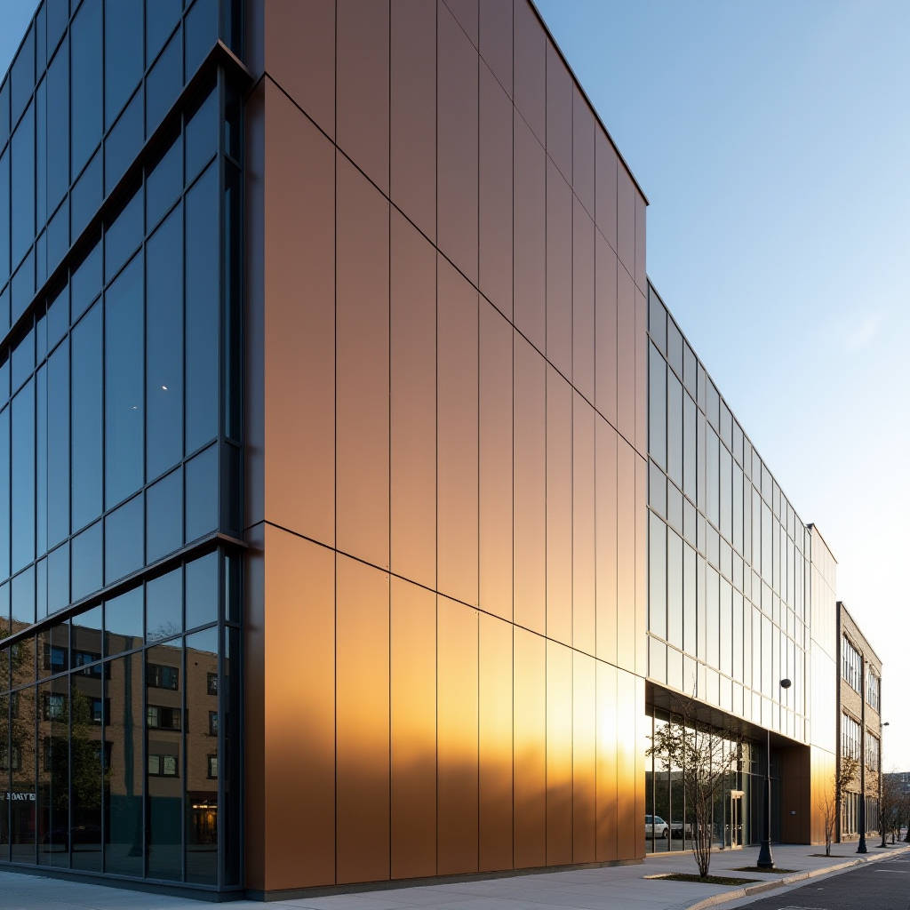
When a curtain wall consultant specifies a Tray Aluminum Panel system, they are not simply picking a flat sheet of metal. They are selecting an engineered, folded-edge cassette that dictates how water drains, how wind loads transfer through the substructure, and how the facade reads visually from street level. A tray panel—also called a folded panel, cassette panel, or return-edge panel—is fabricated from solid aluminium sheet (typically 2.0 mm to 3.0 mm thick) with brake-pressed edges on all four sides. These edges serve as both a structural stiffener and the primary attachment interface for the hidden clip-and-rail system that keeps fasteners invisible. Getting the edge geometry right matters more than most specifiers realize. The depth of the return leg, the radius of the bend, the relief cuts at corners—all of these details determine whether the panel will oil-can under thermal cycling or sit dead flat for 30 years.
What Actually Defines a Tray Aluminum Panel in Facade Engineering
The term "tray" in facade engineering refers specifically to the fabrication method. A flat aluminium sheet—supplied in mill finish, typically from alloys in the 3000 or 5000 series—is cut to a developed blank size, then folded on a CNC press brake to create perpendicular or near-perpendicular return edges. The resulting panel resembles a shallow tray, hence the name. These return edges typically measure 20 mm to 50 mm in depth, depending on the panel's span and the wind load requirements of the project location.
What separates a properly engineered Tray Aluminum Panel from a basic folded sheet is the corner treatment. At each corner, the fabricator must remove material through a notching or relief-cut process before folding. If the notch is too large, the corner leaks water. Too small, and the aluminium tears during forming. The best fabricators use laser-cut relief holes at the bend intersection, which distribute stress evenly and prevent crack propagation. This is not a detail you see on a shop drawing until you ask for it explicitly.
Material choice matters here. Solid aluminium panels for tray systems are almost always supplied in 5052-H32 or 3003-H14 alloys. The 5052 grade offers higher tensile strength (approximately 210-260 MPa) and superior corrosion resistance, making it the default for coastal projects. The 5000 series also handles brake-pressing better than the 6000 series extruded alloys, which can develop micro-cracks at the bend line if the grain direction is not accounted for. A competent fabricator, such as those working with Futeng® specification-grade tray panels, will orient the sheet grain perpendicular to the primary bend axis to minimize the risk of surface cracking.
Why Edge Geometry Controls the Whole System
The return edge on a Tray Aluminum Panel is not just a mounting flange. It is the panel's primary stiffening element. A flat sheet of 2.5 mm aluminium spanning 1,200 mm between supports will deflect visibly under moderate wind suction. Fold that same sheet with a 30 mm return on all four sides, and the panel's moment of inertia increases dramatically. The folded edge acts like a built-in beam, resisting bending across the panel's short span.
This structural behavior means the panel gauge can often be reduced when tray geometry is used, compared to a flat plate with face-fixed fasteners. A 2.0 mm tray panel with 35 mm returns can frequently match or exceed the stiffness of a 3.0 mm flat panel with exposed rivets. The weight savings compound across thousands of square meters, reducing dead load on the primary structure and cutting installation time.
However, the return edge also creates a thermal bridge consideration. The folded aluminium wraps around the panel perimeter, creating a continuous metal path from the exterior face to the interior mounting plane. In cold climates, this can lead to condensation on the back of the panel if the ventilation cavity is not properly designed. The solution is a ventilated rainscreen cavity of at least 50 mm behind the panel, with continuous drainage and ventilation openings at the base and head of each floor level. This allows the aluminium to stay at roughly ambient temperature, minimizing the thermal gradient that drives condensation.
Wind Load Performance and the Hidden Fixing Advantage
One of the strongest engineering arguments for specifying a Tray Aluminum Panel system is how it handles wind loads. In a face-fixed panel, each fastener creates a point load. The panel material around the fastener must resist pull-through, which often dictates a thicker gauge or smaller panel size. In a tray system with a hidden clip-and-rail substructure, the panel's return edge engages with a continuous or intermittent aluminium carrier rail. The wind load is transferred from the panel face into the return edge as a bending moment, then into the clip as a shear force, and finally into the rail and the primary structure.
This load path is more efficient than point fixing. The clip engagement can be designed to allow thermal movement in-plane while restraining out-of-plane deflection. The result is a facade that can accommodate the thermal expansion of aluminium (approximately 2.4 mm per meter per 100°C temperature swing) without buckling or rattling.
For projects in hurricane-prone regions, the clip design becomes critical. A properly engineered tray panel clip will have a minimum engagement depth of 15 mm and will be fabricated from 5052 aluminium or stainless steel with a thickness of at least 1.5 mm. The clip spacing—typically 300 mm to 600 mm on center—must be calculated based on the project's design wind pressure, which is derived from ASCE 7 in the United States or EN 1991-1-4 in Europe. As a reference, a 2.5 mm thick Tray Aluminum Panel measuring 1,200 mm by 600 mm with 35 mm returns and clips at 400 mm centers can typically handle design wind pressures exceeding 2.5 kPa, which covers most urban and suburban locations globally.
Coating Systems and the Edge Coverage Problem
PVDF (polyvinylidene fluoride) coatings dominate the architectural aluminium market for good reason. A 70% PVDF resin system, applied at a minimum dry film thickness of 30 microns per AAMA 2605, provides exceptional resistance to chalking, fading, and chemical attack. But there is a problem specific to tray panels: the return edges.
When a flat sheet is coated before folding, the coating on the bend line stretches and thins during the brake-pressing operation. If the coating is too brittle, it cracks. If it is too thick, it delaminates. The solution is a combination of proper coating formulation—high-quality PVDF systems have enough elongation to survive a 90-degree bend on 2.0 mm to 3.0 mm aluminium—and careful process control during fabrication. The bend radius should be at least equal to the material thickness (1t minimum), and the bending should be done at a controlled speed, ideally above 15°C ambient temperature to avoid cold cracking of the coating.
The table below summarizes the key performance differences between the major coating specifications used on architectural tray panels:
| Coating Standard | Resin Type | Min. DFT (microns) | Color Retention (10yr) | Coastal Suitability | Typical Warranty |
|---|---|---|---|---|---|
| AAMA 2605 | 70% PVDF | 30 | ΔE ≤ 5 | Excellent | 20-30 years |
| AAMA 2604 | 50% PVDF | 25 | ΔE ≤ 8 | Good | 10-15 years |
| AAMA 2603 | Polyester | 20 | ΔE ≤ 10 | Limited | 5-10 years |
| Qualicoat Class 3 | Powder (Super-durable) | 60 | ΔE ≤ 5 | Excellent | 20-25 years |
| EN 12206-1 | FEVE (Lumiflon) | 30 | ΔE ≤ 4 | Excellent | 25-30 years |
For most commercial projects, AAMA 2605-compliant PVDF is the sweet spot. It delivers proven long-term performance without the cost premium of FEVE-based systems. However, for projects in the Middle East or Southeast Asia where UV exposure is extreme, the higher crosslink density of FEVE coatings can justify the additional 15-20% cost. The key is to specify the standard that matches the project's climate and expected service life, not simply the highest specification available.
Fabrication Tolerances and What They Mean on Site
The difference between a smooth facade and one with visible panel misalignment often comes down to fabrication tolerances. For a Tray Aluminum Panel, the critical dimensions are the overall length and width (which must match the module grid), the return edge depth (which must be consistent for proper clip engagement), and the diagonal measurement (which controls squareness).
Industry-standard tolerances for architectural tray panels are typically ±1.0 mm on length and width for panels up to 1,500 mm, and ±1.5 mm for larger panels. The return edge depth should be held to ±0.5 mm. Diagonal tolerance should not exceed 2.0 mm difference between the two diagonals. These numbers come from the AAMA 609 and 610 standards, which cover fabricated aluminium architectural components.
On site, these tolerances stack up. If the panel is 1 mm oversize and the support rail is installed 1 mm off-grid, the cumulative error at mid-span can reach 2 mm, which is visible to the naked eye at close range. This is why experienced installers always set out from a surveyed grid and adjust each panel position individually. The tray panel's hidden fixing system actually helps here, because the clip engagement slot typically has 2-3 mm of adjustability in the vertical and horizontal directions, allowing the installer to compensate for accumulated tolerances in the substructure.
Perforated Tray Panels and Acoustic Engineering
When a Tray Aluminum Panel is perforated, it becomes part of the building's acoustic strategy. The perforations—typically round holes ranging from 3 mm to 8 mm in diameter, with open areas from 15% to 40%—allow sound energy to pass through the panel face into an absorptive cavity behind. This cavity is usually filled with mineral wool or acoustic fleece, creating a Helmholtz-type absorber that targets specific frequency ranges.
The acoustic performance of a perforated tray panel depends on three variables: the hole diameter, the percentage of open area, and the depth of the cavity behind the panel. Smaller holes (3-4 mm) with 20-25% open area tend to absorb mid-frequency sound (500-2000 Hz), which covers most speech-range noise. Larger holes with higher open areas shift the absorption peak to lower frequencies, which can help with traffic and mechanical equipment noise.
From a fabrication standpoint, perforating a tray panel introduces additional complexity. The perforations must stop short of the fold lines—typically 20-30 mm from the bend—to maintain the structural integrity of the return edge. The perforation pattern must also be aligned with the panel edges so that the visual pattern reads continuously across panel joints. This requires precise CNC programming and careful coordination between the perforation pattern and the panel module size.
Fire Performance and the Solid Aluminium Advantage
Solid aluminium tray panels carry a significant advantage over composite materials in fire performance. Aluminium itself is non-combustible, classified as A1 under EN 13501-1 or rated Class A under ASTM E84 when tested as a standalone material. The critical factor is the complete assembly: the panel, the insulation behind it, and any vapor barriers or weatherproofing membranes.
In a rainscreen system using a Tray Aluminum Panel with mineral wool insulation and a ventilated cavity, the entire assembly can achieve a non-combustible classification. This is increasingly important as building codes worldwide tighten after high-profile facade fires. The ISO 13785 and NFPA 285 standards now govern facade fire propagation in many jurisdictions, and solid aluminium panels with appropriate backing materials consistently pass these tests.
The melting point of aluminium (approximately 660°C) is often raised as a concern. However, in a properly designed rainscreen, the panel is separated from the structural wall by a ventilated cavity. In a fire event, the panel will melt and fall away, but the cavity ventilation limits flame spread behind the panel. The mineral wool insulation behind the panel provides the primary fire barrier, not the panel itself. This is a fundamentally different failure mode from combustible-core composite panels, which can propagate fire vertically through the core material even after the aluminium skins have melted.
Cost Drivers That Procurement Teams Should Understand
Procurement managers evaluating Tray Aluminum Panel bids often focus on the per-square-meter panel price. That number tells only part of the story. The total installed cost breaks down into several components that vary significantly by project:
Material gauge is the most obvious cost driver. Moving from 2.0 mm to 3.0 mm sheet thickness adds roughly 40-50% to the raw material cost, but the installed cost increase is smaller—perhaps 15-20%—because fabrication, finishing, and installation costs remain similar. Panel size also matters. Larger panels reduce the number of joints and clips per square meter, which lowers installation cost, but they increase the risk of oil-canning and may require thicker material. The most economical panel size for tray systems is typically in the range of 600 mm to 900 mm wide by 1,200 mm to 1,800 mm tall, which balances material yield, handling logistics, and installation efficiency.
Coating choice is another significant variable. A standard PVDF solid color might add $15-25 per square meter. A metallic or mica finish can double that. A custom-matched color with a small batch minimum can triple it. The return edges on tray panels also consume coating material that is not visible on the finished facade, which adds 5-8% to the effective coated area compared to a flat panel. This is a hidden cost that catches inexperienced estimators off guard.
Engineering insight: Always request the panel fabricator's bending data sheet for the specific alloy and gauge being proposed. The bend deduction and developed blank size directly affect material utilization, which can swing the raw material cost by 3-5% on large projects.
Installation Sequencing and the Clip-and-Rail Logic
The installation of a Tray Aluminum Panel system follows a bottom-up sequence that is logical but unforgiving of errors. The process starts with setting out the vertical carrier rails, which are typically aluminium T-sections or hat sections fixed to the building's primary structure through thermally isolated brackets. The rails must be plumb within 2 mm over a floor height, and the spacing between rails must match the panel's clip positions exactly.
Once the rails are installed and surveyed, the bottom row of panels is placed. Each panel is lifted into position, and its top return edge engages with the clips on the rail. The panel then rotates down, and the bottom return edge engages with the clips on the rail below. This interlocking sequence means that panels cannot be removed individually—you must start from the top and work down for any replacement. This is a maintenance consideration that facility managers should be aware of.
The horizontal joints between panels are typically open (ventilated) or filled with a gasket or sealant. Open joints, typically 6-10 mm, allow the cavity to breathe and are the preferred approach for ventilated rainscreen systems. Closed joints with gaskets provide better weather protection but reduce ventilation and can trap moisture if the gasket degrades over time. The choice depends on the building's location, exposure, and the performance requirements of the air and water barrier behind the cavity.
Thermal Movement and Joint Design
Aluminium expands and contracts with temperature changes. A 3-meter-long Tray Aluminum Panel subjected to a 60°C temperature swing (from -10°C on a winter night to 50°C on a summer afternoon in direct sun) will change length by approximately 4.3 mm. If the panel is rigidly fixed at both ends, this movement will cause buckling. The hidden clip system must accommodate this movement through sliding connections.
The typical approach is to use a fixed clip at one end of the panel (usually the top) and sliding clips at the other end and along the sides. The fixed clip establishes the panel's position, while the sliding clips allow thermal movement in-plane. The joint width between panels must be at least twice the maximum expected movement to prevent panels from contacting each other. For most projects, an 8-10 mm joint is sufficient, but in extreme climates (desert or arctic), 12-15 mm joints may be necessary.
This movement accommodation is one of the reasons why tray panel systems outperform face-fixed panels in large-format applications. Face-fixed panels with rigid connections at each fastener point will inevitably develop visible stress patterns over time. The tray system's sliding connections eliminate this problem entirely, provided the clips are properly lubricated or designed with a low-friction bearing surface.
Quality Control Checks That Matter Before Shipment
Before a batch of Tray Aluminum Panel units leaves the fabrication facility, several quality checks should be performed and documented. The most important are dimensional verification, coating thickness measurement, and visual inspection under controlled lighting conditions.
Dimensional checks should verify the length, width, diagonal, return edge depth, and flatness of each panel. Flatness is measured by placing a straight edge across the panel face and measuring the gap. For panels up to 1,200 mm in any dimension, the maximum allowable deviation is typically 2 mm, per The Aluminum Association guidelines for architectural flat sheet products. Panels that exceed this tolerance are at risk of oil-canning, a phenomenon where the panel face buckles under thermal stress and produces visible ripples.
Coating thickness should be measured with a calibrated eddy-current gauge at multiple points across the panel face and on the return edges. The minimum thickness must meet the specified standard (30 microns for AAMA 2605) at all measured points. The color should be checked against the approved sample under both daylight (D65) and incandescent (A) lighting to catch metamerism issues.
Visual inspection should look for scratches, dents, orange peel in the coating, and any signs of cracking at the bend lines. The inspection should be done with the panel held vertically, simulating the installed orientation, because lighting from above can reveal defects that are invisible when the panel is laid flat on a bench.
Making the Specification Work for Your Project
A Tray Aluminum Panel system is not a commodity product. The difference between a facade that performs flawlessly for 30 years and one that develops problems within five years comes down to the engineering decisions made during specification and the quality control enforced during fabrication and installation.
The key decisions are: alloy selection (5052-H32 for most architectural applications), panel gauge (2.0 mm minimum, 2.5 mm for large-format panels, 3.0 mm for high-wind or impact zones), return edge depth (30-35 mm is the practical minimum for proper clip engagement and stiffness), coating specification (AAMA 2605 PVDF as the baseline, with FEVE for extreme UV environments), and joint design (open joints with 8-10 mm gaps for ventilated rainscreens).
These parameters should be locked in early, during the design development phase, not left to the contractor's shop drawing process. The shop drawings should be a refinement of an already-specified system, not a redesign. When the specification is clear and the quality benchmarks are defined, the procurement process becomes a comparison of capabilities and compliance, not a race to the lowest price. And in facade engineering, the lowest price almost always costs more in the long run.