Interlocking Aluminum Panel Dry Joint Engineering for Commercial Rainscreen Facades
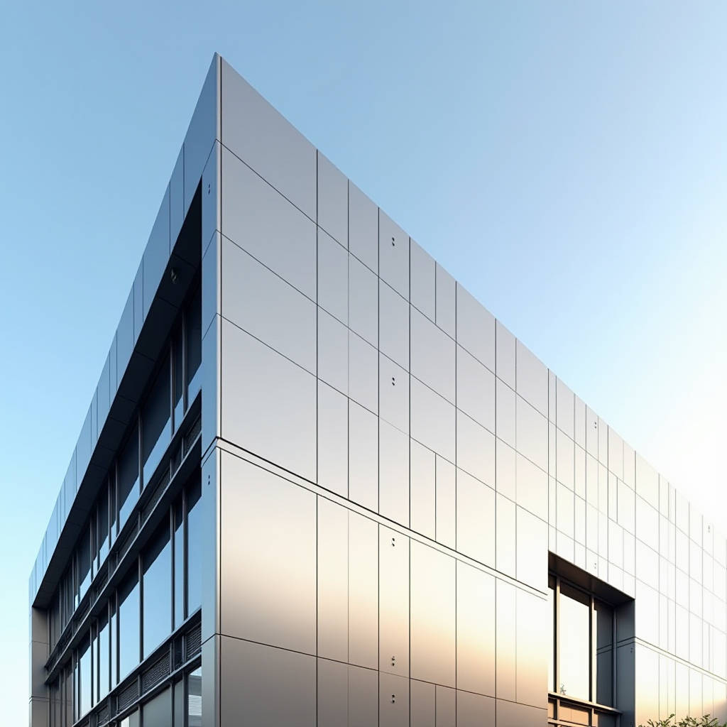
When a rainscreen facade fails, the culprit is rarely the aluminum itself. More often, water finds its way through a sealant joint that was never applied correctly on site, or a gasket that compressed unevenly during rushed installation. Interlocking Aluminum Panel systems address this vulnerability at the design level—eliminating the reliance on wet seals and instead using precision-engineered mechanical joints that shed water by geometry alone. For contractors and specifiers working on mid-rise commercial envelopes, healthcare facilities, or coastal projects where driven rain is a constant threat, understanding how these dry-joint interlocking panels perform under real-world conditions determines whether a facade delivers on its 30-year promise or becomes a maintenance liability within five.
What Defines a True Interlocking Aluminum Panel System
The term "interlocking" gets thrown around loosely in architectural metal cladding, but the engineering distinction matters. A genuine Interlocking Aluminum Panel system uses a male-female edge profile that mechanically engages along panel perimeters—typically both horizontally and vertically—creating a continuous, gasketed or dry-joint connection without requiring face-fastened screws or exposed sealant beads. This is not a snap-lock insulated panel with a foam core, nor is it a simple shiplap overlap. The interlocking geometry on solid aluminum panels (typically 2.0mm to 3.0mm thickness, 5052 or 6061 alloy) is CNC-routed or brake-formed into the panel edges during fabrication, with tolerances held to ±0.5mm to ensure consistent engagement across thousands of square feet.
The panels themselves are fabricated from solid aluminum sheets—not composite laminates. A 2.5mm-thick 5052-H32 aluminum panel with a PVDF (polyvinylidene fluoride) coating system meeting AAMA 2605 standards delivers a facade that resists oil-canning, handles thermal movement predictably, and maintains color integrity for decades. The interlocking joint is where the real engineering value lives: it accommodates thermal expansion and contraction through controlled slip planes within the joint, eliminates the scheduling dependency of on-site sealant application, and speeds up installation by roughly 25-40% compared to conventionally sealed panel systems, based on contractor feedback from North American mid-rise projects.
Dry-Joint Mechanics: Why Geometry Beats Sealant
Sealant has a lifespan. Even the best architectural-grade silicone, properly applied under ideal conditions, will need replacement within 15-20 years. In practice, sealant joints on vertical facades face UV degradation, substrate movement, and installation inconsistencies that can cut that service life in half. An Interlocking Aluminum Panel with a properly designed dry joint bypasses this entire failure mode.
The joint typically incorporates a multi-stage defense against water ingress. The outer interlock geometry breaks the kinetic energy of wind-driven rain. A pressure-equalization chamber behind the interlock allows air pressure on both sides of the panel to balance, neutralizing the force that would otherwise push water through the joint. Finally, a hidden internal gutter or drainage channel captures any moisture that does penetrate and directs it down and out through weep holes at the base of each panel course. This is the rainscreen principle executed at the panel joint level, not just at the cavity behind the entire cladding assembly.
For contractors, the practical impact is straightforward: no callbacks for re-sealing, no scaffolding erected years later to dig out failed joints, and no arguments about whether the sealant installer followed the manufacturer's temperature and humidity requirements. The joint performs the same on day one as it does on day 5,000.
Thermal Movement Accommodation in Interlocking Joints
Aluminum expands and contracts. A 3-meter-long panel of 6061-T6 aluminum subjected to a 60°C temperature swing (from -10°C in winter to 50°C surface temperature under summer sun) will change length by approximately 4.2mm. If the cladding system locks panels rigidly together without accommodating this movement, the result is buckling, fastener fatigue, or joint deformation.
Interlocking Aluminum Panel systems address this through engineered clearance within the joint. The male rib does not bottom out in the female channel; there is a calculated gap that allows each panel to move independently. The interlock maintains engagement and water-shedding geometry throughout the full range of thermal movement. This is particularly critical on south-facing facades in continental climates, where daily temperature swings can exceed 30°C, and on dark-colored panels with high solar absorptance.
The table below summarizes thermal movement ranges for common aluminum panel alloys and lengths, providing a quick reference for specifiers evaluating interlocking system suitability.
| Panel Alloy | Coefficient of Thermal Expansion (mm/m/°C) | Panel Length (m) | Movement at ΔT=60°C (mm) | Movement at ΔT=80°C (mm) |
|---|---|---|---|---|
| 5052-H32 | 0.0238 | 2.0 | 2.86 | 3.81 |
| 5052-H32 | 0.0238 | 3.0 | 4.28 | 5.71 |
| 6061-T6 | 0.0234 | 2.0 | 2.81 | 3.74 |
| 6061-T6 | 0.0234 | 3.0 | 4.21 | 5.62 |
| 3003-H14 | 0.0232 | 3.0 | 4.18 | 5.57 |
Specifiers should verify that the interlocking joint design provides at least 1.5 times the calculated maximum thermal movement as available clearance. Suppliers like Futeng® provide joint movement data as part of their standard engineering submittal package, which eliminates guesswork during shop drawing review.
Wind Load Performance and Interlocking Joint Integrity
Wind doesn't just push on a facade—it pulls. Negative wind pressure on leeward walls and corners can exert suction forces that challenge the mechanical engagement of interlocking joints. A panel that locks together beautifully under gravity may behave differently when a 3.0 kPa suction load tries to pull the male rib out of the female channel.
The interlocking joint's resistance to disengagement under suction is a function of rib geometry, material thickness, and the spacing of any secondary retention clips. For solid aluminum panels at 2.5mm thickness with a 15mm-deep interlocking rib, the joint can typically resist pull-out forces exceeding 4.0 kPa when supported by clips at 600mm centers. This should be verified through project-specific testing per ASTM E330 (Standard Test Method for Structural Performance of Exterior Windows, Doors, Skylights, and Curtain Walls by Uniform Static Air Pressure Difference).
For high-wind zones—coastal Florida, the Gulf Coast, typhoon-prone regions of Southeast Asia—the interlocking system should be tested to 1.5 times the design wind load with no permanent deformation. Some manufacturers offer enhanced interlocking geometries with deeper engagement or secondary locking tabs specifically for these conditions. The engineering cost of specifying a higher-grade interlocking joint is marginal compared to the liability of a panel dislodging at height.
Installation Sequence and Labor Efficiency
The labor economics of Interlocking Aluminum Panel systems are compelling once crews understand the sequence. Unlike face-fastened panels that require precise screw placement through pre-drilled holes, interlocking panels are installed from the bottom up, with each subsequent panel engaging the one below it. The horizontal joints are set first, then vertical joints engage as the panel slides laterally into position.
A typical installation rate for a trained three-person crew is 18-25 square meters per hour for interlocking panels, compared to 12-16 square meters per hour for conventionally sealed and face-fastened systems. The difference comes from eliminating three steps: marking fastener locations, applying sealant to joints, and tooling sealant beads. On a 5,000-square-meter facade, this translates to roughly 150-200 fewer labor hours.
However, the substrate must be flat. Interlocking joints are unforgiving of uneven framing. The industry standard for substrate flatness is a maximum deviation of 3mm over a 3-meter straight edge, measured in both horizontal and vertical directions. If the substrate waves, the interlocking joint binds, panels won't engage fully, and the water-shedding geometry is compromised. The cost saved on sealant labor should be partially reinvested in substrate verification.
Coating Systems and Interlocking Joint Compatibility
The interlocking joint is a zone of mechanical contact and micro-movement. As panels expand and contract, the male and female ribs slide against each other. If the coating system on these contact surfaces is too soft or too thick, it can gall, bind, or wear through, exposing bare aluminum and creating a corrosion site.
PVDF coatings meeting AAMA 2605 standards are the default specification for exterior architectural aluminum. These 70% PVDF resin-based coatings, applied at 25-35 microns dry film thickness, offer the hardness and abrasion resistance needed for interlocking contact surfaces. Polyester powder coatings (AAMA 2604), while less expensive, are softer and more prone to chalking and wear at the joint interface. For interlocking systems, the specification should explicitly call for PVDF on all surfaces, including the interlocking edges—not just the visible face.
Anodized finishes present a different challenge. Anodizing builds an aluminum oxide layer that is extremely hard but can be brittle. In an interlocking joint, the anodic layer on contact surfaces may micro-fracture over thousands of thermal cycles. If anodized interlocking panels are specified, the joint design should include a thin sacrificial polymer bearing strip to prevent metal-to-metal contact. This is a detail that separates experienced facade engineers from those treating interlocking panels as a commodity product.
Water Management: Rainscreen Integration with Interlocking Panels
Interlocking Aluminum Panel systems function best as part of a full rainscreen assembly. The interlocking joint handles water at the outer face, but the cavity behind the panels must be designed to manage any moisture that bypasses the joint—and to allow the wall assembly to dry to the exterior.
A properly detailed interlocking panel rainscreen includes: a continuous air and water barrier on the structural backup wall; vertical and horizontal framing members (aluminum hat channels or galvanized steel Z-girts) creating a minimum 25mm ventilated cavity; open joints at the base and head of the facade to allow air circulation; and flashings at all penetrations, window heads, and base-of-wall conditions that are integrated with the interlocking panel layout, not retrofitted around it.
The cavity ventilation is not optional. Research from the National Fenestration Rating Council and various building science organizations confirms that a ventilated cavity reduces the moisture content of the sheathing and insulation layers behind the cladding, extending the service life of the entire wall assembly. Interlocking panels, because they create a relatively tight outer face, should be paired with generous cavity depths—38mm minimum in wet climates—to ensure adequate airflow.
Comparing Interlocking Panel Substrates: Solid Aluminum vs. Insulated Composites
Not every product marketed as an "interlocking panel" is a solid aluminum cladding panel. Insulated metal panels (IMPs) with interlocking edges serve a different function—they combine cladding, insulation, and air barrier in a single component. They have their place in industrial and cold-storage applications, but for architectural facades where fire performance, longevity, and aesthetic flexibility are priorities, solid aluminum interlocking panels are the appropriate specification.
The table below provides a direct comparison of the two product categories as they relate to architectural cladding applications.
| Performance Attribute | Solid Aluminum Interlocking Panel (2.5mm) | Insulated Metal Panel (IMP) with Interlocking Edge |
|---|---|---|
| Combustibility (NFPA 285) | Non-combustible cladding; passes with appropriate assembly | Foam core may contribute to fire propagation; requires specific testing |
| Service Life (Facade) | 30-50 years with PVDF coating | 20-30 years; foam core may degrade or absorb moisture |
| Thermal Performance | Relies on cavity insulation; panel itself is thermally conductive | Integral insulation; R-value per inch of foam core |
| Joint Water Penetration | Dry-joint rainscreen; pressure-equalized | Sealed joint; relies on gaskets or sealant |
| Panel Flatness | Excellent; solid metal resists pillowing | Prone to thermal bowing and pillowing between stiffeners |
| Customization (Shapes, Perforations) | High; CNC-routable, brake-formable | Limited; foam core constrains fabrication |
| Recyclability (End of Life) | 100% recyclable aluminum | Difficult; foam must be separated from metal skins |
For commercial building facades subject to ASTM E119 fire resistance requirements and NFPA 285 multi-story fire propagation testing, the non-combustible nature of solid aluminum panels simplifies compliance. The interlocking joint itself, being a mechanical connection without foam or sealant, does not introduce combustible materials into the facade assembly.
Quality Control in Interlocking Panel Fabrication
The performance of an Interlocking Aluminum Panel facade is determined at the fabrication stage, not on site. If the interlocking edges are not cut to consistent tolerances, the installer cannot compensate. Panels that are too tight won't engage; panels that are too loose rattle in the wind and leak.
CNC fabrication is non-negotiable for interlocking systems. The routing of panel edges, the positioning of clip slots, and the forming of return legs must be executed with repeatable precision. A quality fabricator will provide a dimensional inspection report for each panel, verifying: overall length and width (±1.0mm), squareness (diagonal difference ≤1.5mm), interlocking edge profile (go/no-go gauge check), and clip slot positioning (±0.5mm).
For projects specifying PVDF coatings, the fabricator should also provide coating thickness measurements (25-35μm per AAMA 2605), gloss readings (25-35 GU for standard colors), and adhesion test results. These are standard documentation items that a reputable supplier provides without being asked. If a fabricator resists providing these reports, the specifier should treat that as a red flag regardless of the quoted price.
Clip and Substructure Design for Interlocking Systems
The interlocking panel gets the attention, but the clip system does the work. Clips connect the panel to the substructure, transfer wind loads, and—crucially—must allow the panel to move freely as it expands and contracts. A clip that grips the panel too tightly defeats the thermal movement accommodation designed into the interlocking joint.
Two clip philosophies dominate the market: fixed clips that anchor the panel at a specific point (typically the center or top edge) and sliding clips that restrain the panel against wind loads while allowing in-plane movement. Most interlocking systems use a combination: one fixed clip per panel to establish its position, with all other clips being sliding types. The sliding clips incorporate a nylon or stainless steel bearing surface that permits movement without galling the aluminum panel's return leg.
Clip material matters. Aluminum clips (typically 6063-T6 extrusions) avoid galvanic corrosion with the aluminum panel. Stainless steel clips (304 or 316 grade) offer higher strength but require an isolation barrier—a thin PVC or EPDM pad—to prevent galvanic reaction, especially in coastal or industrial environments. The cost difference between aluminum and stainless clips is modest (roughly $0.50-1.00 per clip), and for high-corrosion environments, stainless with proper isolation is the conservative choice.
Cost Structure: Where Interlocking Panels Add and Save Money
An Interlocking Aluminum Panel system typically carries a higher material cost than a face-fastened solid aluminum panel system—roughly 10-18% more per square meter, driven by the additional fabrication steps required to create the interlocking edge geometry. However, the installed cost comparison often narrows or reverses when labor, sealant, and long-term maintenance are factored in.
The material premium comes from: CNC routing of interlocking profiles on all four edges (adding approximately 8-12 minutes of machine time per panel), tighter fabrication tolerances requiring more frequent tool changes, and the need for matching left-hand and right-hand panels at corners and terminations. These are real costs that a fabricator must recover.
The savings come from: elimination of field-applied sealant (material cost of $3-6 per linear meter, plus labor), faster installation (25-40% fewer labor hours), reduced scaffolding time, and the near-elimination of callbacks for joint-related water leaks. On a lifecycle cost basis spanning 30 years, the interlocking system typically achieves parity or better by year 10-12, once the first re-sealing cycle would have been required on a conventionally sealed facade.
For budget estimation, a solid aluminum Interlocking Aluminum Panel system with PVDF coating, aluminum subframe, and all flashings typically falls in the range of $180-280 per square meter (installed), varying by region, project complexity, and panel thickness. This is a planning number; project-specific quotes will vary based on geometry, access conditions, and local labor rates.
Specifying Interlocking Aluminum Panels: Key Contract Document Clauses
A specification that simply calls for "interlocking aluminum panels" leaves too much room for interpretation. The following performance requirements should be explicitly stated in the specification section covering metal wall panels:
- Material: Solid aluminum sheet, 5052-H32 or 6061-T6 alloy, 2.5mm minimum thickness (or 2.0mm for interior applications, 3.0mm for high-wind zones).
- Joint Design: Mechanically interlocking on all four edges; dry-joint or gasketed; no field-applied sealant required for water penetration resistance.
- Coating: PVDF resin-based coating meeting AAMA 2605; 70% PVDF resin minimum; 25-35μm dry film thickness; color to be selected from manufacturer's standard range.
- Wind Load: System to be tested to ASTM E330 at 1.5x design wind pressure with no permanent deformation of interlocking joint.
- Water Penetration: System to be tested to ASTM E331 at 15% of design wind pressure with no uncontrolled water entry beyond the rainscreen cavity.
- Thermal Movement: Joint design to accommodate calculated thermal movement with a minimum safety factor of 1.5.
- Fabrication Tolerances: Panel dimensions ±1.0mm; squareness ±1.5mm diagonal; interlocking profile within go/no-go gauge tolerance.
- Submittals: Shop drawings showing panel layout, joint details, clip locations, and flashings; structural calculations sealed by a licensed engineer; coating test reports; and a physical mockup panel demonstrating interlocking joint engagement.
Including these requirements in the specification gives the contractor clear compliance criteria and gives the fabricator clear targets. Ambiguity in the specification is the single biggest source of disputes on interlocking panel projects.
Common Failure Modes and How to Prevent Them
Even well-engineered interlocking systems can fail if installation details are overlooked. The three most common failure modes are:
Substrate misalignment is the leading cause of interlocking joint problems. If the framing is out of plane by more than 3mm over 3 meters, panels will not engage fully. The fix is simple but requires discipline: survey the substrate before panel installation begins, and shim or adjust as needed. This is not a step to skip to recover schedule.
Clip over-tightening defeats the sliding mechanism. Installers accustomed to face-fastened systems may torque clip fasteners until they bite into the panel return leg, locking the panel in place. When the panel tries to expand, it buckles. Training should emphasize that sliding clips are not to be fully tightened against the panel; a 0.5-1.0mm gap is intentional.
Perimeter termination detailing is where many interlocking systems leak—not through the panel joints themselves, but at the interface with windows, louvers, and building corners. The interlocking geometry that works across the field of the wall does not work at terminations. These areas require custom flashings, end dams, and closure pieces that are part of the system, not improvised on site. The specification should require the panel manufacturer to provide engineered termination details for every condition shown on the shop drawings.
Interlocking Panels in Coastal and Corrosive Environments
Salt spray accelerates corrosion in aluminum building products, but the mechanism is well understood and manageable. For Interlocking Aluminum Panel systems within 3 kilometers of a coastline, the specification should be upgraded in several ways: 5052-H32 alloy (which has better corrosion resistance than 6061-T6 in marine environments), PVDF coating with a minimum 30μm dry film thickness, stainless steel fasteners and clips (316 grade), and isolation pads at all aluminum-to-dissimilar-metal contact points.
The interlocking joint itself, being a dry joint, has an advantage in coastal environments: there is no sealant to degrade under UV and salt exposure, and the joint can be washed by rain, which removes salt deposits before they concentrate and initiate corrosion. However, the internal surfaces of the interlocking joint—the hidden contact faces—should be coated, not bare aluminum. A fabricator that ships interlocking panels with uncoated edges is creating a future corrosion site that will be invisible until the panel is removed.
Interlocking Aluminum Panel systems represent a mature, tested approach to rainscreen cladding that prioritizes mechanical water management over chemical sealing. For specifiers willing to invest in substrate preparation and quality fabrication, the payoff is a facade that performs predictably across decades of thermal cycling, wind loading, and weather exposure.
Selecting the right system comes down to verifying the engineering details: joint geometry that accommodates thermal movement, clip systems that allow panels to move freely, coating systems that withstand abrasion at contact surfaces, and a fabrication process that delivers consistent tolerances. These are verifiable, measurable attributes—not marketing claims. A specification that demands evidence for each of these points will produce a facade that works, regardless of which qualified manufacturer ultimately supplies the panels.