Prefabricated Aluminum Panel Systems Engineering and Installation for Commercial Facades
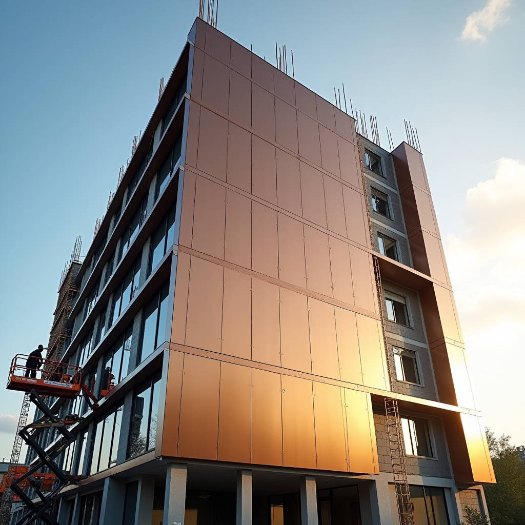
When a project timeline shrinks and the facade scope still demands millimeter-level precision, the conversation among project managers and facade consultants inevitably turns to the Prefabricated Aluminum Panel. This is not about generic cladding sheets cut on site with nibblers and hope. It is about solid aluminum panels — typically 2.0 mm, 2.5 mm, or 3.0 mm thick, fabricated to exact shop-drawing dimensions under controlled factory conditions, complete with folded returns, integrated stiffeners, and pre-applied PVDF or polyester coatings. The value proposition sits squarely at the intersection of dimensional accuracy, installation speed, and long-term weathering performance. A Prefabricated Aluminum Panel arrives on the truck ready to hang, not ready to fabricate. For general contractors staring down liquidated damages and architects who refuse to compromise on joint tolerances, that distinction matters more than most specification sheets admit.
What the Term "Prefabricated" Actually Means in Facade Engineering
In aluminum cladding, "prefabricated" is not a marketing label. It describes a defined manufacturing sequence that shifts labor, quality control, and dimensional risk from the jobsite to the factory floor. A standard solid aluminum sheet — typically alloy 3003 or 5052 per ASTM B209 — arrives at the fabrication facility as mill-finish coil or flat sheet. The prefabrication process then includes CNC cutting to net size, routing corner reliefs, brake-forming perimeter returns (commonly 20 mm to 35 mm deep), and integrating aluminum stiffener profiles bonded or welded to the rear face. For rainscreen applications, the panel may also receive pre-mounted clip systems, extruded edge rails, or cassette-style interlocking profiles.
The key difference from field-fabricated panels is geometric certainty. A Prefabricated Aluminum Panel is produced on CNC turret punches and press brakes with repeatability tolerances typically within ±0.5 mm on length and width, and ±1.0 mm on diagonal measurements. Field-fabricated panels, cut with portable shears and bent on site, rarely achieve better than ±3.0 mm — and that gap widens when the installer is working at height, in wind, on a December afternoon. The factory also applies the coating in a controlled environment, which matters because PVDF (polyvinylidene fluoride) systems require precise oven dwell times and cure temperatures to achieve the inter-coat adhesion that delivers 20-year-plus exterior durability.
Material Specifications That Define a Solid Prefabricated Panel
Specifying a Prefabricated Aluminum Panel begins with the aluminum substrate itself. The two workhorse alloys in architectural cladding are 3003-H14 and 5052-H32. The former offers excellent formability and corrosion resistance at moderate cost; the latter delivers higher tensile strength (approximately 31 ksi vs. 22 ksi for 3003-H14) and better performance in coastal or high-wind environments. Thickness selection is not arbitrary. A 2.0 mm panel works for soffit applications and low-rise interiors. For exterior facades above three stories, 2.5 mm is the practical minimum, and 3.0 mm is standard for panels exceeding 1.2 square meters or where wind loads exceed 1.5 kPa design pressure.
Coating systems follow AAMA 2605 for high-performance architectural applications. The standard PVDF architecture is a three-coat system: a chrome-based or chrome-free pretreatment layer, a corrosion-inhibiting primer (typically 5-8 microns), a color coat (20-25 microns), and a clear topcoat (12-15 microns). Total dry film thickness should fall between 35 and 45 microns. The resin system must contain a minimum of 70% PVDF resin by weight in the color coat — anything less, and the specification falls to AAMA 2604, which is a different performance category entirely. For projects within 5 km of breaking surf or heavy industrial zones, the specification should mandate a marine-grade pretreatment and a minimum 3.0 mm panel thickness.
Factory Processes That Determine Panel Quality
The quality of a Prefabricated Aluminum Panel is established long before the first sheet hits the press brake. The fabrication sequence typically follows six stages: incoming material inspection, CNC blanking, forming, stiffener integration, surface finishing, and final quality assurance. Each stage carries specific failure modes that procurement managers should understand.
Incoming material inspection verifies mill certificates against the purchase order — checking alloy designation, temper, thickness tolerance (per ASTM B209, typically ±0.08 mm for 2.5 mm sheet), and surface condition. CNC blanking uses turret punches or fiber lasers to cut the developed flat pattern, including corner relief notches that prevent cracking during brake forming. The forming stage bends the perimeter returns; the critical parameters here are bend radius (minimum 1.5 times material thickness to avoid stress cracking) and springback compensation. Stiffener integration involves attaching aluminum extrusions to the rear face using either structural adhesive (two-part epoxy or polyurethane) or intermittent aluminum welding. The adhesive method is increasingly preferred because it eliminates heat-affected zones and weld distortion.
Surface finishing for PVDF systems requires a multi-stage spray line with chemical pretreatment, primer application, color coat, and clear coat, each followed by oven curing at 230°C to 250°C. The final QA stage checks dimensional conformity, coating thickness (using eddy-current gauges), adhesion (cross-hatch test per ASTM D3359), and color consistency (spectrophotometer reading with Delta E typically below 1.5).
Installation Methods and Their Impact on Project Economics
How a Prefabricated Aluminum Panel mounts to the building structure determines not just aesthetic outcomes but also thermal performance, weathertightness, and installation productivity. Three dominant systems exist in current practice, and the choice among them ripples through the entire project budget.
The cassette system uses panels with folded edges that interlock, creating a flush or recessed joint appearance. Panels typically hang on horizontal or vertical aluminum support rails using pre-attached brackets. This system is the fastest to install — experienced crews can achieve 30 to 50 square meters per installer per day — and it delivers the cleanest joint lines. However, cassettes require the tightest fabrication tolerances because joint misalignment is immediately visible.
The tray panel system uses panels with returns on all four sides, secured to a subframe with exposed mechanical fasteners or concealed clips. This is the workhorse for ventilated rainscreen applications. The rear-ventilated cavity (typically 38 mm to 50 mm) drives natural convection that manages moisture and reduces cooling loads. Tray systems are more forgiving of substrate irregularities because the subframe can be shimmed during installation.
The hook-on system employs panels with folded top and bottom edges that hook onto continuous horizontal rails. This approach eliminates visible fasteners entirely and allows individual panel removal for access to the cavity — a genuine advantage for buildings where facade maintenance access is constrained. The trade-off is higher fabrication cost per panel due to the specialized edge profiles.
The table below compares key performance parameters across these three systems, based on data from multiple completed projects and industry installation benchmarks.
| Parameter | Cassette System | Tray Panel System | Hook-On System |
|---|---|---|---|
| Typical panel thickness | 2.5–3.0 mm | 2.0–3.0 mm | 2.5–3.0 mm |
| Installation speed (m²/installer/day) | 30–50 | 18–30 | 20–35 |
| Joint appearance | Recessed/flush, 10–20 mm | Open or closed, 6–15 mm | Shadow gap, 8–12 mm |
| Fastener visibility | None (concealed) | Exposed or semi-concealed | None (concealed) |
| Individual panel removal | Difficult | Moderate | Easy |
| Substrate tolerance requirement | ±3 mm over 3 m | ±5 mm over 3 m | ±4 mm over 3 m |
| Relative fabrication cost | Medium-High | Medium | High |
Thermal Performance and the Rainscreen Principle
A Prefabricated Aluminum Panel installed as part of a ventilated rainscreen does more than shed rain. The cavity behind the panel creates a thermal buffer zone. In summer, solar radiation heats the aluminum outer skin, and the ventilated cavity dissipates that heat before it reaches the insulation layer and the building interior. In winter, the cavity acts as a pressure-equalization zone that prevents cold air from driving moisture into the wall assembly. The physics is well-documented: a properly designed rainscreen with a minimum 38 mm ventilated cavity, open at base and head, can reduce the effective thermal load on the building envelope by 15% to 25% compared to a barrier wall system, depending on climate zone and orientation.
For specifiers, the critical detail is the placement of the continuous insulation layer directly on the exterior face of the structural backup wall, behind the cavity. Mineral wool or rigid foam insulation boards are typical, with thickness determined by the project's U-value target. The aluminum panel itself contributes negligible thermal resistance — aluminum's thermal conductivity is approximately 205 W/m·K — but its role in shielding the insulation from UV degradation and mechanical damage is substantial. The panel-to-subframe connection must incorporate thermal breaks, typically nylon or PVC isolators, to prevent thermal bridging through the aluminum support rails.
Wind Load Performance and Structural Engineering
Wind load governs the structural design of every Prefabricated Aluminum Panel system. The design process follows ASCE 7 for projects in North America, EN 1991-1-4 for European projects, or the relevant national code for other regions. The engineer calculates design wind pressure based on basic wind speed, building height, exposure category, and internal pressure coefficients. That pressure is then applied to the panel as a uniformly distributed load, and the panel's bending capacity, stiffener spacing, and clip capacity are verified against the demand.
A typical 2.5 mm thick 3003-H14 panel spanning 600 mm between stiffeners can resist approximately 1.8 kPa to 2.2 kPa design pressure, depending on the stiffener profile and connection method. For high-rise facades where corner zones experience amplified suction pressures (often 2.5 to 3.5 times the zone pressure), panel thickness may increase to 3.0 mm and stiffener spacing may tighten to 400 mm. The clip-to-subframe connection requires particular attention: each clip must resist both the normal wind load and the dead load of the panel, and the fastener embedment into the backup wall must account for the substrate material — concrete, steel stud, or CMU all demand different anchor types and edge-distance requirements.
Testing validates the engineering. ASTM E330 governs static wind load testing of exterior wall systems; panels are subjected to both positive and negative pressures at 150% of design load and must not exhibit permanent deformation exceeding 0.2% of span. For projects in hurricane-prone regions, ASTM E1886 and E1996 address impact resistance and cyclic pressure loading. A Prefabricated Aluminum Panel system that has passed these tests provides documentation that the engineer of record can rely on.
Coastal and Corrosive Environment Specifications
Marine environments expose aluminum cladding to chloride-laden aerosols that accelerate corrosion. The standard 3003-H14 alloy with PVDF coating performs adequately in most coastal settings, but projects within 500 meters of breaking surf demand upgraded specifications. The alloy should shift to 5052-H32 or even 5083-H116 for superior pitting resistance. The pretreatment must be chrome-based or a validated chrome-free alternative with proven salt-spray performance per ASTM B117 exceeding 3,000 hours. Coating thickness should increase to a minimum 50 microns total dry film thickness.
Beyond the panel itself, the support system requires equal attention. Stainless steel fasteners (grade 304 as minimum, 316 for direct coastal exposure) are non-negotiable. Aluminum subframe components should be anodized or powder-coated, and any steel backup framing must be hot-dip galvanized to ASTM A123 with a minimum coating weight of 600 g/m². Dissimilar metal contact points must be isolated with nylon washers or EPDM gaskets to prevent galvanic corrosion. The cavity must remain open and well-drained; any accumulation of salt-laden moisture against the panel rear face will eventually compromise even the best coating system.
Supply Chain and Procurement Strategy
Procuring Prefabricated Aluminum Panel systems for a major facade package involves lead times, logistics, and quality assurance that extend well beyond a simple purchase order. The typical lead time from approved shop drawings to delivery at site ranges from 8 to 14 weeks, depending on panel complexity, coating system, and factory capacity. The shop drawing phase itself — during which the fabricator develops panel layout drawings, joint details, and interface coordination with windows, louvers, and other facade elements — typically consumes 3 to 5 weeks and requires close collaboration with the architect and structural engineer.
For international projects, shipping adds another layer of planning. Solid aluminum panels are heavy: a 2.5 mm panel weighs approximately 6.8 kg/m², plus stiffeners and packaging. A 40-foot container holds roughly 800 to 1,200 square meters of panels, depending on panel sizes and packaging configuration. Ocean freight from Asian fabrication hubs to North American or European ports takes 3 to 5 weeks, plus customs clearance and inland transport. Procurement managers should factor in these durations when establishing project milestones.
Quality surveillance during fabrication is standard practice. Third-party inspection agencies can verify material mill certificates, dimensional accuracy, coating thickness, and adhesion at the factory before shipment. This step is particularly valuable when the fabricator is new to the project team or when the specification demands are unusually stringent. A reliable supplier with documented project experience — Futeng®, for example, has supplied solid aluminum panel systems across multiple international markets with consistent quality documentation — reduces the inspection burden but does not eliminate the need for due diligence.
Common Failure Modes and How to Prevent Them
Even a well-specified Prefabricated Aluminum Panel system can underperform if certain failure modes are not anticipated. The most common issues observed in the field include oil canning, coating delamination, fastener corrosion, and joint misalignment.
Oil canning — the visible waviness or buckling of flat panel surfaces — is an optical phenomenon, not a structural failure, but it generates more disputes than almost any other cladding issue. It arises from residual stresses in the aluminum sheet, introduced during rolling, that are released unevenly during fabrication or thermal cycling. Prevention starts with specifying H14 temper (which has been stress-relieved) rather than H18, using thicker material (2.5 mm minimum for large flat panels), and designing stiffener patterns that break the panel into smaller sub-spans. Some fabricators also perform a light stress-relief pass on the panel surface before coating.
Coating delamination typically traces back to inadequate pretreatment. If the aluminum surface is not properly cleaned, etched, and conversion-coated, the primer cannot achieve the chemical bond required for long-term adhesion. The specification should mandate a minimum 24-hour cure period after coating before panels are packaged, and packaging materials must not contact the coated surface directly. Interleaving with foam or paper sheets prevents transit abrasion.
Fastener corrosion in the cavity is often a specification oversight — stainless steel fasteners are specified for the panel face but carbon steel screws are used for the subframe connections behind the cavity. Every metallic component in the wall assembly must be evaluated for corrosion resistance appropriate to the exposure environment. Joint misalignment, finally, is usually a construction tolerance issue rather than a fabrication defect. The backup wall must be surveyed before subframe installation, and the subframe must be adjusted to achieve the flatness required by the panel system — typically ±3 mm over a 3-meter straightedge.
Cost Structure and Value Engineering
Understanding the cost breakdown of a Prefabricated Aluminum Panel package helps procurement teams make informed value-engineering decisions. The material cost of the aluminum sheet itself typically represents 30% to 40% of the panel price. Fabrication — cutting, forming, stiffener integration — accounts for 25% to 35%. Coating adds 15% to 25%, depending on the system (PVDF three-coat is at the high end; polyester single-coat at the low end). The remaining 10% to 20% covers packaging, factory overhead, and margin.
Value engineering should focus on parameters that genuinely affect cost without compromising performance. Panel size optimization is the single most powerful lever: standardizing panel dimensions reduces CNC setup time and material waste. Reducing the number of unique panel types — by rationalizing the facade grid — cuts shop drawing effort and fabrication complexity. Coating system selection is another lever: for sheltered soffits or interior applications, a polyester system meeting AAMA 2603 may be fully adequate and costs significantly less than PVDF. However, reducing panel thickness below 2.5 mm for exterior applications is a false economy; the savings are modest and the risk of oil canning and wind-load failure increases substantially.
Installation labor is the wild card. In high-cost labor markets, the speed advantage of a cassette or hook-on system can offset its higher material cost. A system that installs at 40 m²/day versus 20 m²/day halves the labor component of the installed cost — and on a 10,000-square-meter facade, that difference can run into six figures. The procurement decision should therefore evaluate the installed cost, not just the panel supply price.
Quality Standards and Testing References
Several industry standards govern the specification, testing, and performance verification of Prefabricated Aluminum Panel systems. The Aluminum Association's Aluminum Design Manual provides the basis for structural calculations. ASTM B209 covers aluminum and aluminum-alloy sheet and plate, establishing chemical composition and mechanical property requirements. AAMA 2605 defines the performance requirements for high-performance organic coatings on aluminum extrusions and panels, including color retention, chalk resistance, and gloss retention after accelerated weathering.
For the complete wall assembly, ASTM E283 covers air leakage, ASTM E331 addresses water penetration under static pressure, and ASTM E330 governs structural performance under wind load. The American Architectural Manufacturers Association (AAMA) publishes installation guidelines that complement these test standards. In Europe, EN 13501-1 addresses fire classification, and EN 13830 covers curtain walling product standards. Specifiers should reference the standards applicable to the project's jurisdiction and ensure that the fabricator's quality management system aligns with ISO 9001 requirements.
Mock-up testing deserves specific mention. A full-scale visual mock-up, built on site using the actual panel system, subframe, and installation crew, reveals interface issues that shop drawings cannot capture. The mock-up should include typical panel joints, corner conditions, window and louver interfaces, and parapet terminations. It serves as the quality benchmark for the production installation and is referenced in the contract documents as the standard of workmanship. The cost of a mock-up — typically 1% to 2% of the facade package value — is negligible compared to the cost of rectifying systemic installation defects discovered after production panels are installed.
Making the Right Specification Decision
The specification of a Prefabricated Aluminum Panel system is a multi-variable optimization problem. Panel thickness, alloy grade, coating system, stiffener design, attachment method, cavity depth, insulation strategy, and fastener material all interact. The optimal solution for a low-rise office building in a temperate inland climate looks nothing like the optimal solution for a 40-story residential tower on a tropical coastline. The common thread is that quality is determined in the factory, verified by testing, and proven on the mock-up.
For the project team, the practical takeaway is to engage a fabricator early — ideally during design development, not after the tender documents are issued. Early engagement allows the fabricator to advise on panel sizes that minimize waste, joint configurations that suit the architectural intent, and attachment methods that align with the structural engineer's assumptions. It also allows the team to evaluate the fabricator's quality documentation, project references, and testing capabilities before the procurement clock starts ticking. A Prefabricated Aluminum Panel system that is specified thoughtfully, procured carefully, and installed competently will deliver decades of low-maintenance performance — and that is the outcome every facade engineer is ultimately paid to achieve.