Aluminum Ceiling Facade Engineering for Exterior Soffits and Canopies
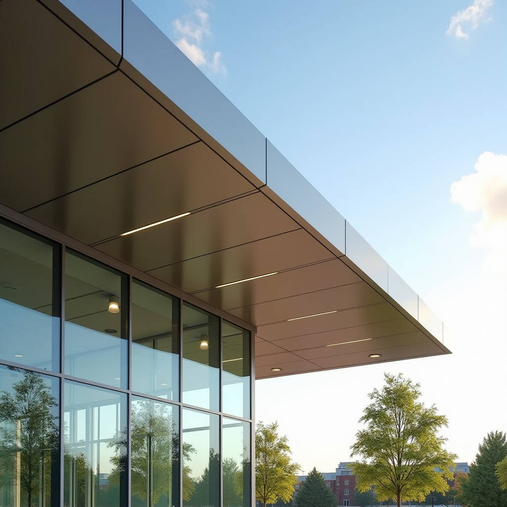
When a project calls for an overhead architectural surface that must withstand decades of weather exposure without warping, delaminating, or losing its finish, specifiers turn to the Aluminum Ceiling Facade as a load-bearing, fully non-combustible exterior solution. Unlike interior suspended ceilings that hang below a weatherproof roof, an Aluminum Ceiling Facade functions as the primary exterior skin of soffits, canopies, entrance portals, and large-span horizontal cladding zones. The material doing the heavy lifting here is solid aluminium sheet, typically 2.0mm to 3.0mm thick, fabricated into panels with folded return edges, welded corners, and structural reinforcement ribs. This article examines the engineering demands that separate a properly executed Aluminum Ceiling Facade from a cosmetic ceiling panel, focusing on wind load mechanics, drainage geometry, coating longevity, and the supply chain realities that procurement managers face when sourcing from manufacturers like Futeng®.
What Separates an Exterior Ceiling Facade from an Interior Ceiling System
The distinction matters because the failure modes are entirely different. An interior suspended ceiling fails when it sags, discolors, or loses acoustic performance. An Aluminum Ceiling Facade installed outdoors fails when water ponds on the panel surface, when wind uplift tears fasteners out of the substructure, or when thermal expansion buckles the panel field over a 40°C diurnal temperature swing. The design logic shifts from aesthetic modulation to structural survivability. Exterior panels carry live loads: wind suction on soffits can reach negative pressures of 1.5 kPa or more depending on building height and exposure category. Snow accumulation on horizontal canopy surfaces adds dead load. The panel joint must simultaneously allow for thermal movement, drain rainwater, and resist wind-driven moisture ingress. These are not concerns that interior ceiling manufacturers typically address in their standard product lines.
Material thickness is the first filter. Interior ceiling panels commonly use 0.6mm to 1.0mm aluminum. An Aluminum Ceiling Facade panel starts at 2.0mm and frequently goes to 2.5mm or 3.0mm for spans exceeding 1,200mm. The extra mass provides the bending stiffness needed to resist wind pressure without oil-canning. It also allows for welded corner construction rather than crimped or clipped corners that can open up under cyclic loading. The finish system differs as well: exterior panels require PVDF fluoropolymer coatings meeting AAMA 2605 standards, with a minimum total dry film thickness of 30 microns over a chrome-based conversion coating. Interior panels might use polyester powder coatings that chalk and fade within 3-5 years of UV exposure.
Wind Load Engineering for Horizontal Cladding Surfaces
Wind behaves differently on horizontal and near-horizontal surfaces than on vertical walls. On a vertical facade, wind pressure distributes relatively predictably across zones defined by building geometry. On a soffit or canopy, the airflow separates at the building edge and creates fluctuating suction forces that can oscillate. The relevant design standard in most international projects is ASCE 7, which provides pressure coefficients for open and partially enclosed structures. For an Aluminum Ceiling Facade on a high-rise podium canopy, the designer must calculate both the outward (suction) pressure on the underside and any downward pressure on the top surface, then design for the net differential.
A practical starting point: a 3m x 1.2m solid aluminum panel in a 50m-high building located in a 150 mph wind zone might experience design wind pressures in the range of 1.8 to 2.4 kPa. The panel's allowable deflection under this load, per NAAMM guidelines, should not exceed L/180 for exterior applications. For a 1,200mm span, that means maximum deflection of 6.7mm. A 2.5mm thick 3003-H14 aluminum sheet with properly spaced stiffeners can achieve this. The stiffener spacing, stiffener section depth, and attachment method become the critical design variables that determine whether the panel passes or fails.
The attachment system deserves equal scrutiny. Exterior Aluminum Ceiling Facade panels should never rely on friction-fit clips alone. Each panel needs positive mechanical fasteners at all four corners, with intermediate clips spaced according to the wind load calculation. Stainless steel screws or rivets, minimum grade 304, are standard. In coastal environments, 316 stainless becomes mandatory. The substructure—typically aluminum T-sections or steel channels—must be independently fixed to the primary structure with anchors rated for the calculated pull-out loads.
Drainage Geometry and Water Management
Water is the enemy of any horizontal exterior surface. An Aluminum Ceiling Facade that traps water will eventually develop staining, corrosion at fastener penetrations, and in freezing climates, ice damage that can pry open joints. The panel design must incorporate a minimum slope of 2% (1:50) across the surface, though 3% is safer for large spans. This slope can be built into the panel itself through tapered fabrication or into the substructure layout.
Joint design is where many projects go wrong. An open joint of 10mm to 15mm allows water to drain freely and provides the thermal expansion gap needed for aluminum's coefficient of linear expansion (approximately 2.4mm per linear meter per 100°C temperature change). For a 3m panel experiencing a 60°C temperature range from winter night to summer sun, the length change is roughly 4.3mm. The joint must accommodate this movement without binding. Some designs incorporate a hidden gutter system behind the open joint, which catches and channels water to perimeter drains. This approach keeps the visible surface clean while managing bulk water behind the scenes.
Perforated panels add another layer of complexity. When an Aluminum Ceiling Facade uses perforated sheets for acoustic absorption or visual effect, the perforations become thousands of water entry points. The backing layer—typically a black acoustic fleece or a solid aluminum backing tray—must be detailed to prevent water from pooling between the perforated face and the backing. A drainage path at the panel perimeter is essential. The percentage of open area in perforation patterns typically ranges from 15% to 35%, and the hole diameter affects both the acoustic performance and the drainage behavior.
Coating Systems and Long-Term Weather Resistance
The coating on an Aluminum Ceiling Facade takes more punishment than a wall coating. Horizontal surfaces receive higher UV dosage, especially in low-latitude locations. They also collect airborne contaminants that vertical surfaces shed through rain washing. The industry benchmark for exterior aluminum is PVDF (polyvinylidene fluoride) coating, which contains a minimum of 70% PVDF resin by weight in the color coat. This resin system resists chalking, fading, and chemical degradation for 20+ years in most environments.
The following table compares coating options for exterior aluminum ceiling applications based on performance data from coating manufacturers and industry testing:
| Coating System | Resin Type | Dry Film Thickness | UV Resistance (Years to Chalking) | Salt Spray Resistance | Typical Cost Index |
|---|---|---|---|---|---|
| PVDF 70% (AAMA 2605) | Kynar 500 / Hylar 5000 | 30-40 microns | 20-25 | 4,000+ hours | 1.0 (baseline) |
| FEVE Fluoropolymer (AAMA 2605) | Lumiflon-based | 30-40 microns | 20-25 | 3,000+ hours | 0.95 |
| Super Durable Polyester (AAMA 2604) | Polyester / silicone-modified | 25-35 microns | 10-15 | 1,500+ hours | 0.70 |
| Standard Polyester (AAMA 2603) | Polyester | 20-25 microns | 5-8 | 1,000+ hours | 0.55 |
| Anodized Finish (AA-M12C22A31) | Aluminum oxide layer | 15-25 microns | 15-20 | 3,000+ hours | 0.85 |
For any Aluminum Ceiling Facade exposed to direct sunlight, AAMA 2605-compliant PVDF is the minimum defensible specification. The cost premium over polyester pays back within the first recoating cycle that a polyester finish would require. Color selection also matters: dark colors absorb more solar radiation and can reach surface temperatures of 80°C or higher in summer, which accelerates thermal movement and stresses the coating-substrate bond. Light to medium colors are thermally more forgiving.
Fabrication Tolerances and Panel Flatness
Panel flatness becomes visually critical on horizontal surfaces because low-angle sunlight casts long shadows across any deviation. A 2mm wave that would be invisible on a vertical wall becomes a noticeable shadow line on a soffit at 4pm. The relevant standard for flatness is typically a maximum deviation of 0.5% of the panel's diagonal dimension, measured under ambient shop lighting. For a panel with a 2,500mm diagonal, that means no more than 12.5mm of total deviation from a true plane.
Achieving this requires disciplined fabrication. The aluminum sheet must be leveled before cutting. CNC routing of the perimeter and any openings must be done with sharp tooling to avoid edge burr that telegraphs through the flat surface. Reinforcement ribs are welded to the back face using intermittent stitch welding to minimize heat distortion. The rib pattern—typically a grid of aluminum hat sections or C-channels—is designed to break the panel into smaller unsupported spans, each of which can be held flat by the rib stiffness. Post-weld, the panel may require light re-leveling before the coating process begins.
For large-format Aluminum Ceiling Facade panels exceeding 2m in any dimension, factory pre-assembly and inspection are worth the extra logistics cost. A panel that leaves the factory flat will stay flat if handled correctly. A panel that leaves with built-in stress will telegraph that stress through the coating over the first thermal cycle.
Acoustic Considerations for Exterior Soffit Applications
Sound control is not the first thing that comes to mind with exterior cladding, but it matters in specific contexts. An Aluminum Ceiling Facade under a highway overpass, a stadium canopy, or a transit station entrance can reflect traffic noise, crowd noise, or train announcements in ways that create unpleasant acoustic environments. Perforated panels backed with acoustic fleece or mineral wool absorbers can reduce reflected sound energy by 3 to 6 dB(A), which is perceptually significant.
The acoustic performance of a perforated aluminum panel depends on three parameters: the open area percentage, the hole diameter, and the depth of the air cavity behind the panel. A typical sound-absorbing configuration uses 20-25% open area with 2.5mm to 3mm diameter holes, backed by a 50mm thick acoustic fleece or non-combustible mineral wool. The system acts as a Helmholtz resonator, with peak absorption tuned to the frequency range of interest—typically 500 Hz to 2,000 Hz for speech and traffic noise. Testing per ISO 354 or ASTM C423 provides the sound absorption coefficients that acoustic consultants use in their models.
Fire Performance and Non-Combustibility
Building codes globally are tightening requirements for exterior cladding materials following several high-profile fires. An Aluminum Ceiling Facade made from solid aluminum sheet is inherently non-combustible. Aluminum itself is classified as A1 or A2-s1,d0 under the Euroclass system per EN 13501-1, and meets the non-combustible criteria of ASTM E136. This is a fundamental advantage over composite panels that contain polyethylene or mineral-filled cores, which may require additional testing and documentation to satisfy code officials.
The fire consideration for solid aluminum panels shifts from the panel itself to the system components. The acoustic backing material, if used, must be non-combustible or have limited combustibility. The gaskets and sealants at panel joints should be selected for low smoke and low toxicity. The substructure—whether aluminum or steel—does not introduce fuel load. Specifiers should request full system fire test reports, not just material-level certificates, when the Aluminum Ceiling Facade forms part of a fire-rated assembly such as a canopy over an exit path.
Supply Chain and Procurement Strategy
Procurement managers dealing with an Aluminum Ceiling Facade package face a different set of challenges than those buying standard interior ceilings. The panels are project-specific: each one has unique dimensions, edge profiles, perforation patterns, and attachment details. Lead times typically range from 8 to 14 weeks from approved shop drawings, depending on factory capacity and the complexity of the scope. The shop drawing phase itself can take 3 to 5 weeks, during which the manufacturer's engineering team resolves interface details with the facade consultant and the structural engineer.
Material sourcing matters. The aluminum coil should be from mills with consistent temper and surface quality. For PVDF-coated panels, the coating applicator should be certified by the resin manufacturer (e.g., PPG or AkzoNobel) to apply their licensed coating system. This certification ensures that the pretreatment, primer, and color coat are applied within the process window that the resin chemistry requires. Manufacturers like Futeng® maintain these certifications and can provide the documentation chain that traces each panel batch back to the coil certificate and the coating batch number.
Shipping and handling require planning. Exterior-grade panels with PVDF finishes ship with protective film on the exposed face. The film should be UV-resistant if the panels will be stored outdoors at the site for more than a few weeks. Panels should ship vertically in custom crates with padded separators. Horizontal stacking risks abrasion and permanent deformation of the lower panels under the weight of the stack. On-site, the panels need covered storage, ideally in a conditioned space if the project is in a humid coastal environment where condensation can form between the film and the coating.
Installation Sequence and Quality Control
The installation of an Aluminum Ceiling Facade follows a sequence that must be coordinated with the general contractor's schedule. The substructure goes up first: aluminum grid systems or steel channels aligned to the design slope and leveled to the specified tolerance, typically ±3mm over any 3m length. The substructure alignment determines the final panel alignment, so this step warrants a hold point for survey verification.
Panel installation starts from a fixed reference point, typically a building corner or a structural column line, and proceeds outward. Each panel is set to the design joint width using spacer tools or temporary shims. The fasteners are tightened to the specified torque—over-tightening can dimple the panel face, while under-tightening leaves the panel loose under wind load. After installation, the joint widths are checked with a go/no-go gauge, and the surface flatness is checked with a straightedge under representative lighting conditions.
A common quality issue is the "zipper effect," where a small alignment error at the starting panel propagates and magnifies across the panel field. Catching this early, within the first three to four rows, prevents a cascade of rework. The installation crew should include someone whose sole job is to sight along the joint lines and call out deviations before they compound.
Cost Drivers and Value Engineering
The cost of an Aluminum Ceiling Facade breaks down into material, fabrication, finishing, and installation. Material cost is driven by aluminum ingot pricing plus the rolling premium for the specified alloy and temper. Fabrication cost scales with complexity: simple rectangular panels with no perforations are the baseline; curved panels, panels with multiple openings for lighting and sprinklers, and panels with custom edge returns add labor hours. Finishing cost depends on the coating specification and the number of color changes in the project.
Value engineering on an Aluminum Ceiling Facade should focus on reducing fabrication complexity without compromising performance. Standardizing panel sizes reduces the number of unique shop drawings and CNC programs. Minimizing the number of color changes reduces coating line downtime. Using a single panel thickness throughout the project, even if some panels could be thinner, simplifies procurement and reduces the risk of installation errors. The cost savings from these measures often exceed the marginal material savings from thinning the panel gauge.
Panel flatness, joint alignment, and coating integrity are the three quality pillars that define a successful Aluminum Ceiling Facade installation. If these three are right, the visual result will be right. If any one of them is compromised, the deficiency will be visible from ground level, and it will be permanent.
The engineering behind an Aluminum Ceiling Facade rewards careful attention to wind load calculations, drainage geometry, thermal movement accommodation, and coating specification. The panels themselves are straightforward in concept—solid aluminum sheets, fabricated and finished to order—but the system design around them determines whether the installation performs for five years or thirty. For procurement teams, the key is to engage with manufacturers who have in-house engineering capability, certified coating processes, and a track record of delivering exterior-grade panels to international projects. The specification should be clear on material thickness, alloy, coating standard, and performance testing requirements. When these elements are in place, the result is an overhead surface that handles weather, loads, and time with equal competence.