Tower Aluminum Facade Wind Load Engineering Panel Gauge Stiffener and ASTM Standards
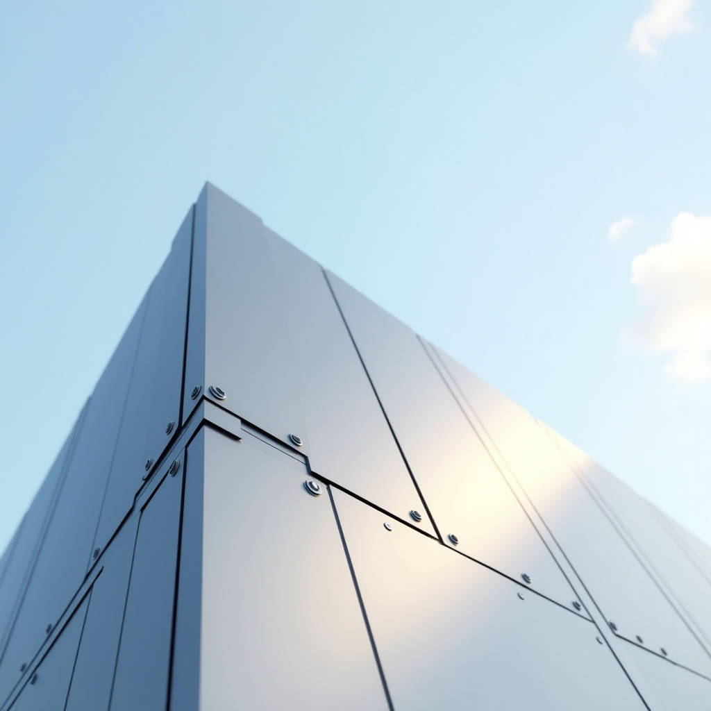
Wind loading on a tower facade is not a uniform pressure problem. It is a zone-by-zone engineering challenge where peak negative pressures at building corners can exceed the mean pressure by a factor of 2.5 or more. For a Tower Aluminum Facade system, the difference between a spec that holds through a storm and one that buckles at the first gale often comes down to whether the panel gauge, stiffener layout, and fixing method were selected with wind tunnel data or just a code-minimum assumption. This article examines how solid aluminum cladding panels perform under high negative wind loads, what the ASTM and AAMA standards actually require, and how to specify panel thickness, alloy selection, and sub-frame anchoring so that the facade stays flat, quiet, and watertight across a 50-year service window.
How Wind Load Translates to Facade Stress on High-Rise Towers
Wind pressure on a tower facade is rarely uniform. The highest positive pressures typically hit the windward face at roughly 80% of building height, while the most severe negative pressures (suction) concentrate at corners, eaves, and parapets. A 150-meter tower in a coastal city can see design wind pressures exceeding 3.5 kPa on corner zones, compared to 1.2 kPa on the mid-span of the same elevation. This disparity matters because a Tower Aluminum Facade system is only as strong as its weakest panel-to-subframe connection in the highest-load zone.
The mechanism is straightforward: wind flowing around a rectangular tower accelerates at the building corners, creating a sharp drop in external pressure. The resulting suction tries to pull the cladding panel away from the substructure. For solid aluminum panels, the failure modes to watch are not panel rupture — aluminum at 2.5mm or 3.0mm thickness rarely tears — but rather:
- Excessive deflection that causes visible oil-canning or permanent deformation
- Fixing pull-out where screws or rivets tear through the panel edge under cyclic loading
- Sub-frame rotation where the aluminum extrusion supporting the panel twists under suction, loosening the entire assembly
ASCE 7-22 provides the baseline for calculating design wind pressures across building zones. However, code values alone are insufficient for towers above 100 meters. A wind tunnel study conducted by a boundary-layer wind tunnel laboratory (BLWTL) generates zone-specific Cp (pressure coefficient) values that often exceed code defaults by 20-35% at corners. Specifying a Tower Aluminum Facade without this data is guesswork dressed as engineering.
Panel Thickness and Alloy Selection: The Numbers That Hold the Line
Solid aluminum cladding panels for tower facades are typically specified in 2.0mm, 2.5mm, or 3.0mm thickness from 3003-H14 or 5005-H14 alloy. The choice between them is not aesthetic — it is a direct function of the panel's span, the design wind pressure, and the allowable deflection limit.
For a 1,200mm x 3,000mm panel with a 600mm stiffener spacing, a 2.0mm 3003-H14 panel under 2.0 kPa suction can deflect beyond L/60, which is visually unacceptable on a tower facade where reflected light reveals every ripple. Moving to 2.5mm reduces deflection by roughly 40% for the same span and loading. At corner zones where suction can reach 3.5 kPa, 3.0mm panels with 400mm stiffener spacing become the baseline.
Alloy selection matters because 5005-H14 offers approximately 10% higher yield strength than 3003-H14 (140 MPa vs. 125 MPa), translating to better resistance against permanent set under cyclic wind loading. For towers in hurricane-prone regions — Miami-Dade County, the Gulf Coast, or typhoon corridors in Southeast Asia — 5005-H14 or even 5052-H32 should be the default for corner-zone panels.
Futeng® has supplied solid aluminum panels in 5005-H14 alloy for multiple high-rise projects where wind tunnel data indicated corner-zone suction exceeding 4.0 kPa, and the engineering submittals included panel-by-panel deflection calculations tied to the wind tunnel Cp map.
ASTM and AAMA Standards That Govern Wind Performance
Several standards directly govern the wind-load performance of a Tower Aluminum Facade. Understanding which standard applies to which test is essential for writing a specification that holds up under review.
| Standard | Scope | Key Requirement for Tower Facades |
|---|---|---|
| ASTM E330 / E330M | Structural performance of exterior windows, doors, skylights, and curtain walls under uniform static air pressure | Panel assembly must withstand 1.5× design wind pressure without permanent damage; tested at both positive and negative pressure |
| AAMA 501.1 | Dynamic water penetration test using a calibrated spray rack and wind generator | Facade must show zero water penetration at 15% of design wind pressure; critical for tower corners where suction drives water into joints |
| ASTM B209 / B209M | Standard specification for aluminum and aluminum-alloy sheet and plate | Defines tensile strength, yield strength, and elongation for 3003-H14, 5005-H14, and 5052-H32; mill certs must accompany every batch |
| AAMA 2605 | Voluntary specification for high-performance organic coatings on aluminum | PVDF coating must pass 4,000+ hours of salt spray (ASTM B117) and 10+ years of South Florida exposure without chalking above rating 8 |
ASTM E330 testing is the gatekeeper. A panel assembly that passes at 1.5× design pressure with deflection under L/175 at the center span is generally considered acceptable. However, many tower projects now specify L/240 or even L/360 for visible facade areas, particularly where glossy or metallic PVDF coatings make any deviation immediately apparent. Meeting L/360 at 3.0 kPa negative pressure on a 1,200mm span typically requires 3.0mm 5005-H14 panels with stiffeners at 350mm centers — a spec that adds roughly 15-20% to panel cost compared to a 2.5mm 3003-H14 solution but eliminates the risk of post-installation oil-canning disputes.
Stiffener Design: The Hidden Engineering That Determines Facade Flatness
Stiffeners on the back of a solid aluminum panel are the primary defense against wind-induced deflection. The common practice of spot-welding aluminum hat-section stiffeners at 600mm centers works for low-rise applications but is inadequate for tower facades where wind suction governs.
The critical parameters for stiffener design on a Tower Aluminum Facade include:
- Stiffener profile: Hat sections (typically 25mm deep × 40mm wide) offer better torsional stiffness than flat bars, which matters when wind loads are not perfectly perpendicular to the panel face
- Attachment method: Structural adhesive combined with intermittent welding provides a continuous load path and eliminates the stress concentrations that pure mechanical fastening creates at each weld point
- Spacing-to-thickness ratio: A rule of thumb: stiffener spacing (in mm) should not exceed 120 × panel thickness (in mm) for corner-zone panels. For a 2.5mm panel, that means 300mm maximum spacing
- End condition: Stiffeners must terminate within 50mm of the panel edge; leaving a 100mm+ unsupported edge creates a flap that vibrates audibly under gusting wind
Vibration is an under-discussed failure mode. Even when a panel meets deflection criteria under static load, gust-induced vibration can fatigue the stiffener-to-panel bond over thousands of cycles. AAMA 501.4, which covers dynamic wind load testing, is increasingly referenced in tower facade specifications for this reason. The test subjects a full-scale mockup to 9,000 cycles of positive and negative pressure, simulating a 50-year wind fatigue life. Panels that pass static ASTM E330 but fail AAMA 501.4 are not uncommon — the failure typically manifests as stiffener detachment or permanent deflection accumulating cycle by cycle.
Sub-Frame and Anchoring: Where the Load Path Meets the Structure
The aluminum panel is one link in a chain that extends from the panel face, through the stiffeners, into the aluminum sub-frame, across the bracket system, and finally into the building's primary structure. Weakness at any link compromises the entire Tower Aluminum Facade system.
Sub-frame design for high-wind towers must address three load cases simultaneously:
- Wind suction (negative pressure): Tries to pull the panel and sub-frame away from the building. Brackets must resist tension and the anchor bolts must have adequate pull-out capacity from the concrete substrate.
- Wind pressure (positive pressure): Pushes the panel toward the building. Sub-frame members must resist buckling between bracket supports.
- Thermal movement: A 3-meter aluminum panel on a tower facade can expand and contract by 6-8mm between summer and winter. The sub-frame must accommodate this movement without transferring stress to the panel or the anchors.
For a typical tower application, the sub-frame consists of vertical aluminum T-profiles or hat-sections anchored to the slab edge or structural wall at 1,200mm to 1,500mm centers. The bracket system — usually extruded aluminum with stainless steel components — provides 3-axis adjustability for installation tolerance while maintaining structural continuity. A well-designed bracket transfers both tension and compression loads without relying on friction connections, which can loosen under cyclic loading.
Anchor selection is dictated by the substrate. For concrete, stainless steel expansion anchors or undercut anchors are standard; for steel frame buildings, through-bolts or welded connections. The key specification point: every anchor in a corner zone must be rated for at least 2.5× the calculated design tension, accounting for the prying effect that occurs when wind suction acts on a panel that is offset from the anchor plane by the bracket standoff distance.
Coating Integrity Under Wind-Driven Rain and UV
Wind loading and coating performance are not separate topics. A PVDF coating that looks flawless on a calm day can fail within five years if the underlying panel is flexing beyond the coating's elongation limit under wind load. PVDF coatings — whether 70% PVDF (AAMA 2605) or 50% PVDF (AAMA 2604) — have an elongation at break of approximately 20-30%. If the aluminum substrate deflects enough to strain the coating beyond this threshold, micro-cracking initiates, and once moisture reaches the aluminum, filiform corrosion follows.
The practical implication for a Tower Aluminum Facade: specifying a deflection limit of L/175 is not just about aesthetics. It is about keeping the coating strain below 1%, which provides a comfortable safety margin below the 20% failure threshold. At L/175, the maximum strain on a uniformly loaded panel is approximately 0.8%, well within the PVDF coating's elastic range. At L/60 — still structurally safe for the aluminum — coating strain can exceed 3%, and while a single cycle may not cause visible cracking, 10,000 cycles of wind-induced flexing can.
Coastal and industrial environments compound this risk. Salt spray accelerates corrosion at any micro-crack, and acid rain in industrial zones attacks the coating's chemical structure. AAMA 2605 requires 4,000 hours of salt spray resistance, but for towers within 500 meters of a coastline, specifying 5,000 hours and a minimum 35-micron PVDF topcoat (rather than the standard 28-30 microns) is a prudent upgrade that adds roughly 8-12% to the finishing cost.
Engineering a Wind-Resistant Specification: A Practical Checklist
Drawing on field experience across multiple tower projects, the following specification checklist captures the minimum requirements for a Tower Aluminum Facade that will perform under high wind loads:
- Wind tunnel report: Require a BLWTL study or equivalent for towers above 100 meters. Map Cp values to each panel zone on the elevation drawings.
- Panel gauge by zone: 2.5mm minimum for field panels, 3.0mm for corner zones where Cp exceeds -2.0. Alloy: 5005-H14 minimum, 5052-H32 for hurricane zones.
- Stiffener spacing: 400mm maximum for field panels, 300mm for corner panels. Structural adhesive plus intermittent welding.
- Deflection limit: L/240 under 1.5× design wind pressure for all visible panels. L/360 for panels with high-gloss or metallic finishes.
- Testing protocol: ASTM E330 static test plus AAMA 501.4 dynamic cyclic test on a full-scale mockup that includes at least one corner condition.
- Coating: AAMA 2605, 70% PVDF, minimum 35-micron topcoat, 4,000-hour salt spray. 5,000-hour for coastal towers.
- Anchors: Stainless steel, rated for 2.5× calculated tension load. Submit anchor pull-out test results from the actual substrate type.
- Sub-frame: Aluminum extrusions with 3-axis adjustable brackets. Thermal movement gap of 10mm minimum at panel joints.
This checklist is not theoretical. It reflects the lessons learned from projects where panels oil-canned within six months, coatings micro-cracked at stiffener weld points, and sub-frame connections loosened after two storm seasons. Each of these failures was preventable at the specification stage for a cost premium that was a fraction of the remediation expense.
For procurement teams, the practical takeaway is that panel cost per square meter is a misleading metric. A 2.5mm 5005-H14 panel with 300mm stiffener spacing and AAMA 2605 coating costs more than a bare-minimum 2.0mm 3003-H14 panel with 600mm stiffener spacing, but the total installed cost difference — including sub-frame, anchors, labor, and testing — is typically under 15%. Against the cost of scaffolding, panel replacement, and reputational damage from a visible facade failure, that 15% is the cheapest insurance a tower project can buy.
References and Further Reading
- ASCE 7-22: Minimum Design Loads and Associated Criteria for Buildings and Other Structures — ASCE 7-22 Standard
- ASTM E330: Standard Test Method for Structural Performance of Exterior Windows, Curtain Walls, and Doors — ASTM E330
- AAMA 501.1: Standard Test Method for Water Penetration of Windows, Curtain Walls and Doors Using Dynamic Pressure — AAMA 501.1
- AAMA 2605: Voluntary Specification for High Performance Organic Coatings on Architectural Aluminum — AAMA 2605
- ASTM B209: Standard Specification for Aluminum and Aluminum-Alloy Sheet and Plate — ASTM B209
Wind resistance in a Tower Aluminum Facade is not a single specification line. It is a system-level decision that starts with wind tunnel data, flows through panel gauge and alloy selection, depends on stiffener geometry and attachment, and ends with coating integrity under decades of cyclic loading. The engineering exists. The standards are clear. The only question is whether the specification will use them.