Podium Aluminum Facade Engineering for Mixed Use Building Envelope Performance
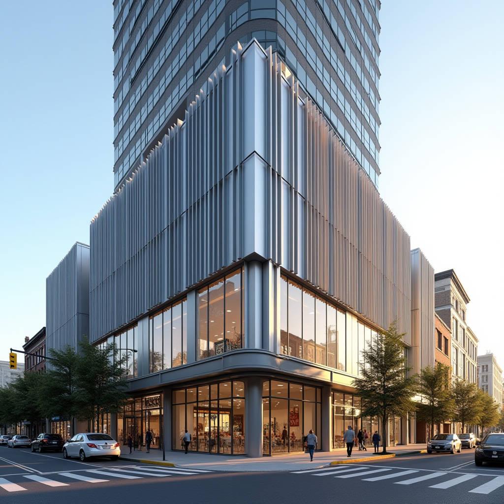
A podium aluminum facade sits at the intersection of architectural ambition and brutal engineering reality. The lower 3 to 10 floors of a mixed-use building carry loads that tower sections never see—vehicle impact zones, pedestrian traffic, retail frontages, ventilation louvers, and abrupt transitions between structural systems. When the cladding material is solid aluminum sheet, every design decision made at the podium level ripples upward through the entire building envelope. Getting the panel gauge, joint geometry, and sub-frame alignment wrong at this stage creates problems that compound floor by floor. This article examines the specific technical demands that podium aluminum facade systems must satisfy, from wind load distribution and thermal movement accommodation to interface detailing where the podium meets the tower above.
Why the Podium Demands a Different Facade Logic
Architects and facade engineers who treat the podium as simply a continuation of the tower curtain wall are setting themselves up for coordination failures. The podium aluminum facade operates under conditions that differ fundamentally from upper-floor cladding.
Ground-level wind behavior is one factor. Wind accelerates around building bases through the Venturi effect, creating pressure differentials that standard tower wind load calculations do not capture. A 2021 study published in the Journal of Wind Engineering and Industrial Aerodynamics documented pressure coefficients at podium corners reaching 1.8 times the values predicted by simplified code-based methods. For a solid aluminum rainscreen panel at 3.0mm thickness, this translates directly into fixing center calculations and stiffener layout requirements.
Impact resistance is another. Building codes including the International Building Code (IBC) Section 1406 and ASTM E1996 specify impact load requirements for cladding within 25 feet of grade. A podium aluminum facade must withstand not only wind-borne debris but also the daily reality of delivery trucks, shopping carts, and maintenance equipment. This is not a theoretical concern—replacement of damaged podium panels accounts for a disproportionate share of facade maintenance budgets in mixed-use developments.
Thermal movement at the podium level also differs from tower conditions. The podium typically spans longer uninterrupted horizontal distances than the tower above, meaning cumulative thermal expansion must be absorbed across fewer vertical breaks. An aluminum panel with a coefficient of thermal expansion of approximately 23.4 × 10⁻⁶ /°C will move roughly 2.8mm per meter across a 50°C temperature swing. Across a 40-meter podium elevation, that is over 110mm of total movement that joint design must accommodate.
Panel Thickness Selection and Structural Performance
Solid aluminum cladding panels for podium applications are typically specified in thicknesses ranging from 2.0mm to 4.0mm, with 3.0mm being the most common for vertical rainscreen applications. The choice is not arbitrary—it follows from deflection limits, wind load requirements, and the panel's aspect ratio.
The table below summarizes the relationship between panel thickness, span, and deflection under a uniform wind load of 1.5 kPa, which is representative of podium-level design pressures in many urban locations:
| Panel Thickness (mm) | Max Span Between Fixings (mm) | Deflection at 1.5 kPa (mm) | Deflection Ratio (Span/Deflection) | Typical Application |
|---|---|---|---|---|
| 2.0 | 400 | 5.8 | 1/69 | Soffit lining, low-wind zones |
| 2.5 | 500 | 5.2 | 1/96 | Vertical rainscreen, moderate exposure |
| 3.0 | 600 | 4.1 | 1/146 | Standard podium facade, urban exposure |
| 3.0 (with stiffeners) | 800 | 3.8 | 1/210 | Large-format panels, high-wind zones |
| 4.0 | 700 | 3.2 | 1/219 | Ground-level impact zones, vehicle areas |
Stiffener ribs, typically aluminum extrusions bonded or mechanically fixed to the panel rear face, extend the achievable span without increasing panel thickness. The bonding method matters: structural silicone bonding provides continuous support and reduces stress concentrations, while mechanical fasteners introduce point loads that must be accounted for in fatigue analysis. For podium applications where panels may be subject to cyclic wind loading over decades, the AAMA 508 standard provides guidance on voluntary specifications for structural silicone sealants used in panel stiffener bonding.
Coating Systems and Long-Term Durability
The coating on a podium aluminum facade does more than provide color. It is the primary defense against corrosion, UV degradation, and atmospheric pollutants—all of which concentrate at street level. Podium panels in urban environments face diesel particulates, de-icing salts in colder climates, and airborne chlorides in coastal locations.
PVDF (polyvinylidene fluoride) coatings dominate the specification landscape for good reason. A 70% PVDF resin system, applied to a properly pretreated aluminum substrate, delivers color retention and chalk resistance that far exceeds polyester or acrylic alternatives. The key performance parameters are summarized below:
| Coating Type | Resin System | Dry Film Thickness (μm) | Color Retention (10 yr, ΔE) | Salt Spray Resistance (ASTM B117) | Expected Service Life |
|---|---|---|---|---|---|
| PVDF (70% resin) | Kynar 500® / Hylar 5000® | 30-40 (3-coat) | ≤ 5.0 | 4,000+ hours | 25-30 years |
| PVDF (50% resin) | Kynar 500® / Hylar 5000® | 25-30 (2-coat) | ≤ 8.0 | 3,000 hours | 15-20 years |
| FEVE Fluoropolymer | Lumiflon® | 30-40 (3-coat) | ≤ 5.0 | 4,000+ hours | 25-30 years |
| Polyester (Super Durable) | Silicone-modified polyester | 25-30 (2-coat) | ≤ 12.0 | 1,500 hours | 10-15 years |
For podium applications, a 3-coat PVDF system with a minimum 35μm total dry film thickness is the prudent specification. The primer layer provides adhesion and corrosion resistance, the color coat delivers the aesthetic, and the clear topcoat adds gloss control and additional UV blocking. Suppliers such as Futeng® manufacture solid aluminum panels with PVDF coating systems applied in controlled factory conditions, which is critical—field-applied coatings cannot match the adhesion and uniformity of a factory-cured finish.
Specifiers should reference ASTM D2244 for color tolerance measurement and AAMA 2605 for the complete performance specification covering film integrity, weather resistance, and chemical resistance of high-performance organic coatings on aluminum.
Interface Detailing: Where the Podium Meets the Tower
No detail in a mixed-use facade causes more headaches than the podium-to-tower transition. The structural systems are often different—the podium may be concrete frame while the tower uses steel, or both may be concrete but with different column grids. Differential movement between the two volumes is inevitable.
The joint at this interface must accommodate three types of movement simultaneously: vertical settlement of the tower relative to the podium, horizontal thermal expansion of both facade systems, and inter-story drift during seismic or wind events. A single expansion joint with a silicone sealant bead is insufficient for anything beyond the simplest low-rise applications.
A properly engineered podium-to-tower interface for a podium aluminum facade typically includes:
- A primary structural break in the aluminum sub-frame, with sliding connections that allow ±25mm of movement in two axes
- A secondary weather seal using EPDM gaskets or silicone weather seals rated for the full movement range
- A pressure-equalized cavity design that prevents water from being driven across the joint by wind pressure differentials
- Continuous insulation and vapor barrier continuity across the joint, detailed to prevent thermal bridging
The open-joint rainscreen approach, where panel joints are deliberately left open (typically 10-20mm), simplifies the interface detailing. Pressure equalization behind the panels reduces the driving force for water penetration, and the open joints accommodate thermal movement without relying on sealant performance. This approach has been used successfully on projects including the Ap Lei Chau 129 podium in Hong Kong, where a 320-meter-long podium block integrates multiple facade types across nine residential towers.
Aluminum Fin Systems for Podium Solar Control
Podium levels often incorporate retail frontages, lobby entrances, and recreational spaces that demand high levels of transparency. Glass-heavy podium facades create solar gain problems that tower floors with smaller window-to-wall ratios do not face. Aluminum fin systems integrated into the podium aluminum facade provide a durable, low-maintenance shading solution.
Extruded aluminum fins, typically in 6063-T6 alloy, can be mounted vertically or horizontally on the podium facade. Fin depth, spacing, and angle determine the shading coefficient. A fin depth of 150-300mm at 300-600mm centers provides effective shading for most orientations while maintaining outward visibility. The fins themselves become architectural elements—tapered profiles, curved geometries, and variable spacing create visual rhythm across the podium elevation.
From a structural standpoint, each fin acts as a cantilever subjected to wind load. The connection to the primary facade structure must resist both bending moment and torsion. For a 300mm-deep fin spanning 3 meters between supports, wind loads at podium level can generate bending moments exceeding 0.5 kN·m, requiring connection brackets designed with a safety factor of at least 2.0 per The Aluminum Association's design guidelines.
Fin systems also affect the maintenance profile of the podium facade. Horizontal fins collect dust and debris, requiring periodic cleaning that vertical fins largely avoid. In coastal environments, salt spray accumulation on horizontal surfaces accelerates corrosion if the anodized or powder-coated finish is not specified for marine exposure. A 25μm anodized layer (AA-M25 per ISO 7599) is the minimum for coastal podium applications, with 30μm or PVDF coating preferred for long-term performance.
Curved and Geometrically Complex Podium Panels
Podium facades increasingly feature curved geometries—concave entrance plazas, convex corner radii, and undulating facades that break the visual mass of the building base. Solid aluminum panels are well-suited to curved applications because the material can be formed into single-curvature and, with the right tooling, double-curvature geometries without compromising structural integrity.
Curved aluminum panels for podium applications are typically produced through roll-forming or press-braking. Roll-forming produces smooth, continuous curves ideal for large-radius applications (typically R ≥ 1000mm for 3.0mm sheet). Press-braking creates segmented curves with discrete bend lines, which can be visually softened by increasing the number of segments and reducing the angle per bend.
The practical limits for curved solid aluminum panels are:
- Minimum bend radius: approximately 2.5 times the material thickness for 3003-H14 alloy, 3.5 times for 5005-H34 alloy
- Maximum panel size for curved sections: typically 1500mm × 3000mm due to handling constraints during forming
- Curved panel tolerance: ±2mm on radius, ±1.5mm on overall dimensions per AAMA 609.1
Curved panels introduce additional complexity in the sub-frame. Each curved panel requires a matching curved support rail, and the fixing points must be positioned to avoid inducing stress concentrations at the curve apex. The hidden-rail mounting systems used in open-joint rainscreen designs are particularly well-suited to curved applications, as the rail can be fabricated to the required radius and the panels clip on without visible fasteners disrupting the curved geometry.
Fire Performance and Code Compliance
Fire safety at the podium level carries heightened importance. Podiums often contain parking, retail, and assembly spaces with higher occupant loads and greater fire loads than upper residential or office floors. The facade system must not contribute to fire spread, and must maintain compartmentation between floors.
Solid aluminum itself is non-combustible (classified as A1 per EN 13501-1 or equivalent). The fire risk in a podium aluminum facade system comes from the ancillary components: insulation materials, vapor barriers, sealants, and the potential for cavity fire spread in rainscreen systems.
Key fire safety requirements for podium facades include:
- Cavity fire barriers at each floor level and at maximum 10-meter intervals horizontally, per NFPA 285 or local equivalent
- Non-combustible insulation (mineral wool, A1 or A2-s1,d0 classification) within the rainscreen cavity
- Fire-rated sealants at all perimeter joints and penetrations
- Ventilation openings at the top and bottom of the cavity sized to allow drainage and pressure equalization without creating a chimney effect in fire conditions
The growing regulatory scrutiny following high-profile facade fires globally has made compliance documentation essential. Specifiers should require full-scale fire test reports or engineering judgments from qualified fire engineers for any podium facade system, not just material-level fire ratings.
Logistics, Tolerances, and Installation Sequencing
The podium aluminum facade is typically installed early in the construction sequence, after the primary structure is complete but before interior fit-out begins. This creates a compressed timeline where panel fabrication lead times must align with site readiness.
Panel fabrication tolerances directly affect installation speed. Solid aluminum panels produced to AAMA 609.1 standards should maintain dimensional tolerances of ±1.0mm on length and width, ±0.5mm on squareness, and ±0.2mm on flatness per 300mm. Panels arriving on site outside these tolerances force installers to make field adjustments—drilling oversized holes, slotting brackets, or shimming connections—that compromise both the weathertightness and the visual quality of the finished facade.
For large podium projects, panel phasing should be planned around the building's construction joints and movement joints. Panels should not bridge across structural movement joints unless specifically detailed to accommodate the expected movement. A phased delivery schedule, with panels for each facade zone delivered in installation sequence, reduces on-site handling damage and storage requirements.
The weight of solid aluminum panels also influences installation method. A 3.0mm panel measuring 1200mm × 2400mm weighs approximately 23 kg, which can be handled by two installers without mechanical lifting. Larger panels, or panels with factory-bonded stiffeners and insulation, may require vacuum lifters or mini-cranes, particularly at the upper podium levels where access from the ground becomes impractical.
Making the Right Specification Decisions
The podium aluminum facade is not simply the bottom few floors of the tower cladding system. It is a distinct technical zone with its own structural demands, environmental exposures, and interface challenges. The specification decisions made for the podium—panel thickness, coating system, joint design, fire strategy, and installation sequence—determine whether the facade performs reliably for decades or becomes a source of ongoing maintenance and liability.
Engineers and specifiers who invest time in the details at the podium level find that the rest of the building envelope falls into place more predictably. The podium is where the facade meets the ground, the public, and the practical realities of building performance. Treating it with the technical rigor it deserves is not optional—it is the foundation of a successful building envelope.