High Rise Aluminum Facade Fastening Systems Engineering Wind Loads and Thermal Movement
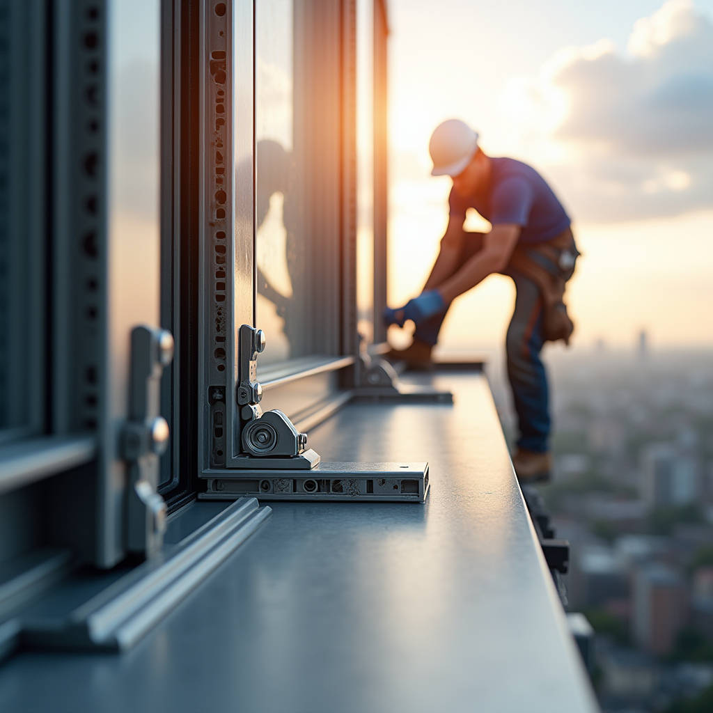
Wind doesn't just push against a tower. It grabs, twists, and sucks at every square meter of cladding with forces that change by the second. For a 40-story building, the difference between a facade that holds and one that fails often comes down to a single engineering decision made months before installation: how the aluminum panels are fastened to the substructure. A High Rise Aluminum Facade lives in a brutal aerodynamic environment where negative pressure at building corners can exceed 4.0 kPa, and vortex shedding creates oscillating loads that fatigue connections over decades. This article focuses on the fastening and subframe engineering that keeps solid aluminum panels exactly where they belong, 120 meters above the street.
What Wind Actually Does to a High Rise Facade
Wind loading on tall buildings follows patterns that are counterintuitive to anyone who hasn't worked directly with facade engineering. The highest pressures don't occur at the top of the building. They concentrate at mid-height corners, where airflow accelerates around the building's edges and creates suction forces that can be 2.5 times higher than the positive pressure on the windward face.
ASCE 7-22 provides the calculation framework most engineers use. For a 150-meter tower in Exposure Category B, the velocity pressure qz at the top calculates to roughly 2.1 kPa. But the external pressure coefficient GCp for corner zones (Zone 5) reaches -3.2 for cladding elements. That means a single 600mm x 1200mm solid aluminum panel at a corner could experience a net uplift force approaching 2,300 Newtons. The fasteners holding that panel must resist that force with a safety factor of at least 2.0 per AAMA TIR-A9-14.
What makes this harder: wind direction changes continuously. A panel that experiences pure suction at 9 AM might be in turbulent cross-flow by 2 PM. The fastening system must handle load reversal without loosening, galling, or creating metal fatigue points. This is where the choice between exposed fastener systems and concealed clip systems becomes an engineering decision rather than an aesthetic one.
Fastening Systems: The Engineering Trade-offs
Three fastening approaches dominate the High Rise Aluminum Facade market. Each solves a different set of problems, and the wrong choice for a specific building geometry creates problems that no amount of panel quality can fix.
Exposed Mechanical Fasteners
Stainless steel screws with EPDM sealing washers, driven through pre-drilled panel faces into aluminum subframe channels. The advantage is straightforward: direct load transfer. Each fastener provides a verifiable connection point, and pull-out values for a #14 self-tapping screw into 3mm aluminum extrusion can exceed 2,800 N per point. For buildings in hurricane-prone regions like Miami-Dade or the Philippines, this verifiable strength matters.
The downside is thermal movement. A 3mm solid aluminum panel measuring 1,200mm in length will expand approximately 1.6mm across a 60°C temperature swing. Rigidly fastened panels transfer that movement stress to the fastener holes, which can elongate over time. The solution is slotted holes with sliding grommets, but this adds fabrication cost and requires precise installation sequencing.
Concealed Clip Systems
Aluminum clips attached to the panel rear face engage with horizontal or vertical carrier rails. The panel face shows no fasteners. This is the dominant approach for premium commercial towers because it delivers clean sightlines. But the engineering is more demanding.
A typical concealed clip arrangement uses two load-bearing clips at the top edge of each panel (carrying dead load) and two restraint clips at the bottom (handling wind suction). The dead load clips must support the weight of the panel itself plus any accumulated ice or maintenance loads. For a 3mm solid aluminum panel at 1.2m x 1.8m, the panel mass is approximately 17.5 kg. The top clips carry that entire weight in shear, plus wind-induced shear components that can double the effective load during a storm event.
Clip engagement depth is critical. A 15mm engagement might seem adequate on the drawing board, but installation tolerances of ±3mm in the subframe, plus ±2mm in panel fabrication, plus ±2mm in clip positioning, mean the actual engagement could be as low as 8mm. That's why specifications like the AAMA 501.4 recommended practice call for minimum 20mm engagement in seismic zones.
Unitized Panel Systems
Large format panels, typically floor-to-floor, are pre-assembled into units with integrated subframes and interlocking joints. The fastening happens at the factory, not on site. Each unit connects to the building structure at four to six anchor points, and the interlocking vertical and horizontal joints transfer wind loads between adjacent units.
This approach shifts the fastening challenge from the panel-to-subframe interface to the unit-to-structure interface. The anchor brackets must accommodate three-dimensional adjustment (in/out, left/right, up/down) while maintaining structural continuity. Three-axis cast aluminum brackets with serrated contact surfaces have become the standard solution, allowing ±25mm of adjustment in each direction without sacrificing load capacity.
Unitized systems make the most sense above 30 stories, where the speed of enclosure offsets the higher upfront engineering cost. A crew can install 15-20 unitized panels per day versus 8-12 stick-built panels, and the quality control advantages of factory assembly are significant for a High Rise Aluminum Facade where rework at height costs exponentially more than rework at grade.
Subframe Materials and Corrosion Compatibility
The aluminum panel gets the attention, but the subframe does the work. Most subframes use 6063-T6 aluminum extrusions, which offer good strength (ultimate tensile around 240 MPa) and excellent corrosion resistance. But the connection between the aluminum subframe and the building's primary structure, typically steel or concrete, introduces galvanic corrosion risk.
When an aluminum subframe bracket bolts to a steel embed plate, the presence of moisture creates a battery. Aluminum acts as the anode and corrodes sacrificially. The standard prevention is a physical barrier: neoprene or EPDM isolation pads of at least 1.5mm thickness at every aluminum-to-steel interface. Stainless steel bolts (316 grade minimum for coastal environments) must use nylon isolation washers under the bolt head and nut.
The following table summarizes the critical fastening parameters across different building height categories:
| Parameter | Low-Rise (Under 25m) | Mid-Rise (25-75m) | High-Rise (75-200m) | Supertall (200m+) |
|---|---|---|---|---|
| Design Wind Pressure (kPa) | 1.0 - 1.8 | 1.8 - 2.8 | 2.8 - 4.5 | 4.5+ |
| Recommended Fastener Type | Exposed SS screws | Concealed clips | Concealed clips + mechanical backup | Unitized with structural anchors |
| Min. Clip Engagement (mm) | 12 | 15 | 20 | 25 |
| Fastener Material Grade | 304 SS | 304 SS | 316 SS | 316 SS + Dacromet |
| Thermal Movement Joint (mm) | 6 | 8 | 12 | 15 |
| Pull-Out Safety Factor | 2.0 | 2.5 | 3.0 | 3.0+ |
| Typical Subframe Profile | T-slot 40mm | T-slot 60mm | Custom box section | Engineered truss system |
Thermal Movement: The Silent Connection Killer
Aluminum expands at roughly 23.4 × 10⁻⁶ per °C. On a black PVDF-coated panel facing the afternoon sun in Dubai or Phoenix, the surface temperature can hit 85°C. At night, it drops to 25°C. That 60°C swing produces 1.68mm of movement per meter of panel length. A 3-meter panel grows 5mm between dawn and mid-afternoon.
If the fastening system doesn't accommodate this movement, something yields. The aluminum panel will buckle, the fasteners will loosen, or the subframe will warp. None of these outcomes are acceptable on a High Rise Aluminum Facade where panel replacement requires a swing stage and a street closure permit.
The engineering solution is to treat each panel as a simply supported element with one fixed point and all other connections allowing sliding. The fixed point, typically at the panel's geometric center or at the top center clip, establishes the datum from which all thermal movement radiates. Sliding connections use elongated holes oriented radially from the fixed point, with PTFE or nylon slip pads that maintain a friction coefficient below 0.15 even after years of exposure.
Testing per ASTM E283 and E331 verifies that these sliding connections maintain air and water barrier integrity through the full range of design movement. A properly designed sliding joint on a 3mm solid aluminum panel can accommodate ±6mm of movement without compromising the weather seal, but this requires precise slot dimensions and careful sequencing of the EPDM gasket installation.
Seismic Considerations for Fastening Design
In seismic zones, the fastening system faces an additional demand: inter-story drift. During an earthquake, the building frame deforms laterally. The facade must follow that deformation without shedding panels. For a typical steel-framed tower, the design inter-story drift can reach H/50, where H is the floor-to-floor height. At 4 meters floor-to-floor, that means 80mm of relative horizontal displacement between the top and bottom of a single panel.
This is why seismic clips differ fundamentally from standard wind clips. A seismic clip must allow the panel to rock and slide within its plane while maintaining vertical load support. The typical solution uses a slotted vertical track with a "dogbone" connector that can rotate ±3 degrees and slide ±40mm. The panel remains attached to the building, but it moves with the frame rather than fighting it.
The FEMA 454 guidelines for seismic design of nonstructural components provide the loading criteria. For a building in Seismic Design Category D, the horizontal seismic design force Fp for a 17.5 kg panel can reach 0.85 kN, which must be resisted without allowing the panel to disengage from its clips. This requires clip geometries with return legs or positive locking features, not simple friction-grip designs.
Installation Tolerances and Quality Control
The best fastening design on paper means nothing if the installation crew can't execute it within the as-built tolerances of the building structure. Concrete frames routinely deviate ±25mm from theoretical position. Steel frames might be ±15mm. The subframe system must absorb these deviations while still delivering a panel plane that's flat within 3mm over any 3-meter length.
Three-axis adjustable brackets are the standard answer. The bracket base attaches to the building's embedded anchor channel using a T-bolt that allows ±30mm of horizontal adjustment. A vertical slotted connection provides ±25mm of height adjustment. Threaded studs or shim packs handle the in/out dimension with ±20mm of range. Once positioned, serrated contact faces or Huck lock bolts prevent creep.
Survey control is the other half of the equation. For a High Rise Aluminum Facade, the installation sequence typically starts with setting corner panels at each floor level using total station survey equipment. These corner panels become the reference plane, and intermediate panels are set relative to them using laser levels and tensioned wire lines. The cumulative error across a 30-meter facade width should not exceed 5mm, which demands careful sequencing and continuous verification.
Futeng® has supplied solid aluminum panels for projects where the installation tolerance requirements were ±2mm across a 40-meter elevation, and achieving that standard required not just precise panel fabrication but also close coordination with the subframe installer to ensure the anchor points were set within the adjustment range of the brackets.
Water Management at Fastener Penetrations
Every fastener that penetrates the panel face is a potential water entry point. The industry has largely moved away from face-fastened systems on high-rise buildings for this reason, but where exposed fasteners are unavoidable, the sealing detail must be robust.
The standard approach uses an EPDM cup washer under the fastener head, compressed to 30-40% of its original thickness when the fastener is torqued to specification. The compression creates a contact pressure that exceeds the expected wind-driven rain pressure. For a building in a region with 75mm/hour design rainfall intensity and 25 m/s wind speed, the dynamic pressure driving water through a leak path is approximately 0.38 kPa. A properly compressed EPDM washer with 1.5 MPa contact pressure provides a safety factor of nearly 4:1.
But EPDM ages. After 15 years of UV exposure and thermal cycling, the compression set can reduce sealing pressure by 40%. That's why the backup defense is a pressure-equalized cavity behind the panel. The outer panel face acts as a rain screen, and the cavity behind it is vented to the outside through open horizontal joints. The pressure inside the cavity equalizes with the outside wind pressure, eliminating the pressure differential that would otherwise drive water inward. The inner air seal, typically a continuous EPDM gasket or membrane, handles any residual moisture.
The ASTM E1105 water penetration test verifies this system by subjecting a full-scale mockup to 15 minutes of water spray at the specified pressure differential. For a High Rise Aluminum Facade, the test pressure is typically 20% of the design wind pressure or 300 Pa, whichever is greater. A passing result shows no uncontrolled water entry on the interior face of the test specimen.
Material Selection for Fasteners in Aggressive Environments
The choice between 304 and 316 stainless steel for fasteners seems like a minor detail until a building 200 meters from a coastline starts showing rust streaks from its panel fasteners three years after completion. Chloride ions from sea spray attack the chromium oxide passive layer on stainless steel. 304 stainless, with roughly 18% chromium and 8% nickel, resists atmospheric corrosion well inland but begins to pit when chloride concentrations exceed 200 ppm. 316 stainless, with 2-3% molybdenum added, tolerates chloride levels up to 1,000 ppm.
For buildings within 5 kilometers of a coastline, 316 stainless fasteners are the minimum specification. Within 500 meters, some engineers specify 316 with Dacromet coating for additional protection, or they switch to aluminum fasteners (6061-T6) to eliminate galvanic coupling entirely. Aluminum fasteners have lower strength, roughly 310 MPa ultimate tensile versus 515 MPa for 316 stainless, so the fastener count or diameter must increase to compensate.
Hydrogen embrittlement is another concern with high-strength steel fasteners. Carbon steel fasteners above HRC 35 hardness can absorb hydrogen during the electroplating process and crack under tensile load. For this reason, mechanically galvanized or Dacromet-coated fasteners are preferred over electroplated zinc when high-strength steel is specified. The ISO 4042 standard for fastener coatings provides the testing framework for hydrogen embrittlement resistance.
Engineering the Right Connection
The fastening system on a High Rise Aluminum Facade is where theoretical design meets physical reality. It's the detail that determines whether the building performs for 50 years or starts shedding panels after 15. The calculations are straightforward: wind loads per ASCE 7, material strengths per ASTM, corrosion resistance per ISO. But the judgment calls, when to use exposed fasteners versus concealed clips, how much engagement depth is enough, whether the thermal movement joint needs to be 8mm or 12mm, come from understanding how these systems behave on real buildings in real weather over real time.
Solid aluminum panels, at 2.5mm or 3.0mm thickness with PVDF or FEVE coating systems, provide the weather barrier and the aesthetic face. But the subframe, the clips, the bolts, and the brackets are what keep those panels on the building. The industry has moved toward concealed, pressure-equalized, seismically compliant fastening systems because they address the full range of demands a tall building places on its skin. The engineering is more complex upfront, but the long-term performance justifies the effort.
For project teams specifying a High Rise Aluminum Facade, the recommendation is to invest engineering time in the fastening details early. Mockup testing per AAMA 501 should include cyclic wind loading, not just static pressure, to verify that connections don't loosen over simulated 50-year storm cycles. The fasteners and clips are the smallest line item on the facade budget, but they carry the largest consequence if they fail.