Commercial Aluminum Facade Engineering Wind Load Deflection and Coating Performance for Solid Panel Systems
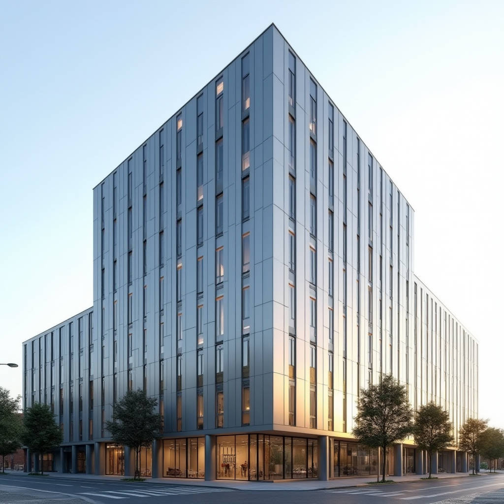
When a commercial building goes up in Chicago, Singapore, or Dubai, the facade is the first thing the market sees. It signals tenant quality, energy strategy, and the owner's tolerance for long-term maintenance. Among the materials competing for that exterior skin, the Commercial Aluminum Facade built from solid aluminium panels has gained ground steadily over the past decade. The reason is not trend-driven. It is a calculation: solid 2.0 mm to 3.0 mm aluminium sheets, finished with PVDF coatings, offer a combination of flatness, corrosion resistance, and fire performance that few other cladding materials can match at comparable cost. This article examines the engineering, procurement, and installation realities behind these systems, with a focus on the issues that general contractors and facade consultants actually lose sleep over: wind load, oil canning, coating longevity, and the gap between shop drawing and site reality.
What Defines a Solid Aluminum Facade System
A Commercial Aluminum Facade is rarely just a panel. It is a rainscreen assembly: an outer skin of solid aluminium sheets, an air cavity, insulation, and a structural back-up wall. The solid panel itself is fabricated from alloy grades typically in the 3000 or 5000 series. Grade 3003-H14 and 5052-H32 are the workhorses. 3003 offers good formability and corrosion resistance at a lower cost. 5052 brings higher tensile strength, which matters for large-format panels where wind suction can cause deflection.
Thickness is a specification that separates serious systems from cosmetic ones. For commercial projects, 2.0 mm is the practical minimum for panels under 600 mm in any dimension. At 800 mm to 1,200 mm spans, 2.5 mm becomes the standard. Panels exceeding 1,200 mm or installed in high-wind zones typically require 3.0 mm. These are not arbitrary numbers. They come from deflection calculations under ASTM E330, which governs structural performance of exterior windows, doors, and cladding under uniform static air pressure.
The fabrication process matters as much as the raw material. Solid aluminium panels are cut, routed, and folded on CNC turret punches and press brakes. The fold lines are back-scored to a precise depth, leaving enough material for a clean 90-degree return without cracking. Welded corners are ground smooth. Reinforcing stiffeners are attached to the rear face with structural adhesive or mechanical fasteners, depending on the system design. Every step affects the panel's final flatness, which is the single most visible quality indicator once the building is in sunlight.
Wind Load and the Deflection Problem
Wind does not push uniformly. It creates positive pressure on the windward face and suction on the leeward side, at corners, and along parapets. The worst-case scenario for a Commercial Aluminum Facade is usually suction at a building corner, where the negative pressure coefficient can be 2.5 to 3.0 times the basic wind pressure. A panel that looks fine under dead load can deflect visibly under a 50-year return period wind gust.
ASTM E1300 provides the framework for calculating allowable deflection. For facade panels, the typical limit is L/60 for the span between stiffeners or attachment points, where L is the clear span in millimeters. On a 1,000 mm span, that means 16.7 mm of deflection is the absolute maximum. But visual acceptability often demands tighter limits. Many specifications now require L/90 or even L/120, particularly for panels with high-gloss or metallic finishes where even slight waviness catches the light.
The calculation itself is straightforward but the inputs are where projects go wrong. Basic wind speed from ASCE 7 must be adjusted for building height, exposure category, and topographic factors. A 45 m/s basic wind speed can translate to a design pressure of 2.5 kPa or more on a 60-meter building in Exposure C terrain. The panel thickness, stiffener spacing, and attachment clip design must all be verified against this number. Cutting corners on stiffeners to save weight is a common source of post-installation deflection complaints.
Oil Canning: The Flatness Challenge
Oil canning is the industry term for visible waviness or buckling in flat metal panels. It is not a structural failure. The panel is not about to fall off. But under certain lighting conditions, the undulations become obvious, and owners notice. In a Commercial Aluminum Facade, oil canning is the most frequent source of disputes between contractors and panel suppliers.
The physics is simple. Aluminium has a coefficient of thermal expansion of approximately 23 × 10⁻⁶ per °C. A 3-meter panel subjected to a 40°C temperature swing will expand by about 2.8 mm. If the panel is restrained at its edges, that expansion has nowhere to go. The material buckles elastically. The same thing happens during fabrication if residual stresses from rolling or bending are not properly managed.
There is no way to eliminate oil canning entirely. The Metal Construction Association's technical bulletin on the subject makes this clear. What can be done is to minimize it through specification. Panel thickness is the first lever: 3.0 mm panels oil-can less than 2.0 mm panels because the stiffness increases with the cube of thickness. Stiffener design is the second: properly spaced hat sections or aluminium extrusions bonded to the rear face constrain the panel against buckling. The third lever is finish selection. Low-gloss PVDF coatings in the 25-35 gloss unit range hide undulations better than high-gloss or mirror finishes.
Coating Systems and the 20-Year Horizon
The coating on a solid aluminium panel does two jobs: it protects the metal from corrosion and it delivers the color that the architect specified. For commercial facades, the industry benchmark is PVDF (polyvinylidene fluoride), applied as a multi-coat system over a chrome-based conversion coating. The standard is a three-coat system: primer, color coat, and clear topcoat, with a total dry film thickness of 30-35 microns. Four-coat systems with a metallic or pearlescent mid-coat push total thickness to 40-45 microns.
The specification that matters most is AAMA 2605, the voluntary standard for high-performance organic coatings on aluminium extrusions and panels. AAMA 2605 requires the coating to pass 4,000 hours of accelerated weathering in a QUV or xenon-arc apparatus with no more than 5 Delta E color change and no more than 8 gloss unit loss. In real-world terms, a properly applied AAMA 2605-compliant PVDF coating should deliver 20 to 25 years of color and gloss retention in most climates.
For projects in coastal or industrial environments, additional testing matters. AAMA 2605 includes a 3,000-hour salt spray resistance test per ASTM B117. The coating must show no blistering and no more than 1/16-inch creep from scribe after exposure. Some suppliers, including Futeng®, offer extended warranties on PVDF systems when the full pretreatment and coating protocol is followed, which can be a useful point of reference during specification review.
The table below compares the key performance attributes of the three coating systems most commonly specified for commercial aluminium facades:
| Property | PVDF (AAMA 2605) | FEVE (AAMA 2605) | Polyester (AAMA 2603) |
|---|---|---|---|
| Dry Film Thickness | 30-45 microns (3-4 coat) | 30-40 microns (3 coat) | 20-25 microns (2 coat) |
| Accelerated Weathering | 4,000 hours | 4,000 hours | 1,500 hours |
| Salt Spray Resistance | 3,000 hours | 3,000 hours | 1,000 hours |
| Expected Service Life | 20-25 years | 25-30 years | 10-15 years |
| Color Retention (Delta E) | ≤ 5 after 10 years | ≤ 5 after 10 years | ≤ 8 after 5 years |
| Relative Cost Index | 100 (baseline) | 115-130 | 55-70 |
| Best Application | Standard commercial facades | Coastal, high-UV, landmark | Interior, sheltered, budget |
Fire Performance and Code Compliance
Fire safety has become the dominant regulatory concern for facade systems globally, driven by high-profile cladding fires in the Middle East, Europe, and Asia. Solid aluminium panels are inherently non-combustible. Aluminium itself carries a Euroclass A1 rating under EN 13501-1 when tested as a standalone material, meaning no contribution to fire at any stage. This is a fundamental advantage over composite panels with polyethylene cores, which can propagate flame vertically through a facade.
However, a Commercial Aluminum Facade is a system, not just a panel. The fire performance of the complete assembly depends on the insulation, the air cavity detailing, and the fire-stopping at floor lines. NFPA 285 in the United States and BS 8414 in the United Kingdom are the two dominant large-scale facade fire tests. Both evaluate the entire wall assembly, including the cladding, insulation, air barrier, and cavity barriers, under a simulated exterior fire.
For projects in jurisdictions that reference the International Building Code, NFPA 285 compliance is mandatory for combustible components in exterior walls of buildings over 40 feet in height. Solid aluminium panels with mineral wool insulation and properly detailed cavity barriers can meet this requirement. The key detail is the horizontal fire stop at each floor line, which must be continuous and mechanically fixed, not simply friction-fit. Vertical cavity barriers at compartment boundaries are equally critical.
In the European framework, the relevant test is BS 8414 or the harmonized EN 13501 classification. The system must achieve a classification report that the local authority accepts. For projects in the Gulf region, many consultants now specify compliance with both NFPA 285 and BS 8414, which creates a testing burden that suppliers must be prepared to address with existing test data rather than project-specific testing.
Installation Systems: Cassette, Tray, and Hook-On
The choice of installation system affects cost, speed, and long-term performance. Three systems dominate the commercial market. Cassette systems use folded panel edges that interlock, with the fixings concealed. Tray panels have open edges and are screwed or riveted to a subframe, with the fixings exposed or covered by a snap-on trim. Hook-on systems use a continuous aluminium extrusion on the rear face that hangs onto a rail fixed to the building structure.
Cassette systems are the premium option. They deliver a clean, joint-free appearance because the panel returns are folded on all four sides and the perimeter joints are uniform. The downside is cost and lead time. Each panel is purpose-made for its location, and field modifications are difficult. Tray systems are faster to install and more forgiving of site tolerances, but the exposed fixings and visible joint lines mean they are typically specified for industrial buildings, parking structures, and secondary elevations rather than prime street frontages.
Hook-on systems occupy a middle ground. They offer concealed fixings and reasonable installation speed, but they require precise alignment of the support rails. If the rails are not within 2-3 mm of design position across the facade, the panels will not hang correctly, and the joints will be uneven. The best practice is to use adjustable brackets on the support rails, allowing 10-15 mm of adjustment in three axes to absorb the accumulated tolerances of the primary structure.
Procurement Strategy and Lead Time Realities
Procuring a Commercial Aluminum Facade involves more than comparing square-meter prices. The supply chain for solid aluminium panels has several distinct stages: aluminium coil production, sheet cutting, fabrication, pretreatment, coating, and packaging. Each stage has its own lead time and capacity constraints.
Aluminium coil is a globally traded commodity. Prices fluctuate with LME (London Metal Exchange) rates, and availability can tighten when automotive or aerospace demand surges. For a typical commercial project requiring 5,000 to 10,000 square meters of panels, the aluminium coil lead time is 4-6 weeks from mill to fabricator. Fabrication adds 3-5 weeks depending on panel complexity and factory loading. Coating, if done in-house, runs in parallel with fabrication. If outsourced, it adds 2-3 weeks of transport and processing time.
The total lead time from approved shop drawings to delivered panels is typically 10-14 weeks. This assumes the shop drawings are approved within two weeks of submission. Delays in drawing approval are the single biggest cause of project schedule overruns in facade procurement. Contractors should budget at least four weeks for the drawing review cycle and build that into the master schedule.
Cost structures vary by region, but a rough breakdown for a mid-specification PVDF-coated solid aluminium panel system is: 35-40% material (aluminium sheet, stiffeners, fasteners), 25-30% fabrication labor, 15-20% coating, and 15-20% overhead and margin. Transport from factory to site adds 3-8% depending on distance and mode. These are indicative ranges, not quotes, but they help frame the conversation when evaluating supplier proposals.
Quality Control: What to Check Before Shipment
The quality of a solid aluminium panel is largely determined before it leaves the factory. Once panels are on site, the options for correction are limited. A structured pre-shipment inspection protocol is the most effective risk management tool available to the buyer.
The first check is dimensional. Panel width, height, and diagonal should be within ±1.0 mm for panels under 1,200 mm and ±1.5 mm for larger panels. Diagonal tolerance is critical because a parallelogram-shaped panel cannot be installed with uniform joints. The second check is flatness. Using a straight edge placed diagonally across the panel, the maximum deviation should not exceed 0.5% of the diagonal length. For a 1,500 mm diagonal, that means 7.5 mm maximum gap.
Coating checks follow. Dry film thickness is measured with a calibrated electronic gauge, taking at least five readings per panel and averaging. Color is checked against the approved sample using a spectrophotometer, with a Delta E of 1.0 or less considered acceptable for production batches. Gloss is measured at 60 degrees, with a tolerance of ±5 units from the specification. Adhesion is tested using the cross-hatch method per ASTM D3359, with a rating of 4B or 5B required.
One often-overlooked check is the quality of the protective film. Panels are shipped with a peelable polyethylene film to prevent scratches during handling and installation. The film must be UV-stable if the panels will be stored outdoors for more than a few weeks. Non-UV-stable film degrades under sunlight, becoming brittle and impossible to remove cleanly, a problem that has generated significant remedial costs on projects where installation was delayed.
Thermal Performance and Energy Code Compliance
A facade is a thermal envelope element. The solid aluminium panel itself has negligible thermal resistance, but the rainscreen system as a whole contributes to the building's energy performance. The air cavity behind the panel acts as a thermal buffer, and the continuous insulation layer on the back-up wall provides the primary thermal break.
For projects governed by ASHRAE 90.1 or local energy codes, the U-factor of the opaque wall assembly must meet prescribed minimums. A typical solid aluminium rainscreen with 100 mm of mineral wool insulation (thermal conductivity approximately 0.035 W/m·K) achieves an assembly U-factor of around 0.30-0.35 W/m²·K. This is sufficient for Climate Zones 4 and below. For colder zones, increasing insulation thickness to 150 mm brings the U-factor down to approximately 0.22 W/m²·K.
The thermal bridging effect of the support system must be accounted for. Aluminium subframe components that penetrate the insulation layer create point thermal bridges. The industry has responded with thermal break solutions: nylon or FRP (fiber-reinforced polymer) isolators placed between the support bracket and the building structure. These can reduce the linear thermal transmittance of the bracket by 50-70%, depending on the design. The cost increment is modest, typically 2-4% of the total facade package, and the energy savings over a 30-year building life usually justify it.
When the Specification Meets the Site
The best facade specification is worthless if the building structure cannot support it. This is where the gap between design and reality opens up. Concrete frames are poured to tolerances of ±25 mm. Steel frames can be worse. The facade system must accommodate these deviations through adjustment at the bracket level.
The standard approach is to design the bracket connection with 25-30 mm of adjustment in the in-out axis and 15-20 mm in the vertical and horizontal axes. This absorbs typical structural tolerances without requiring the panels themselves to be modified. On projects where the structure is significantly out of tolerance, a laser survey of the as-built frame is essential before panel fabrication begins. The survey data is used to adjust the bracket positions, and in extreme cases, to modify panel dimensions.
Interface detailing is the other site-level challenge. The facade must meet windows, louvres, signage, and other penetrations cleanly. These junctions are where water ingress occurs if the detailing is inadequate. The principle is simple: every penetration must have a sill flashing that directs water to the face of the panel, and every horizontal joint must have a continuous seal or an interlocking geometry that prevents water from being driven upward by wind pressure. The execution is harder, and it requires close coordination between the facade contractor and the other trades on site.
A Commercial Aluminum Facade built from solid aluminium panels is a system that rewards careful specification and punishes shortcuts. The panel thickness, stiffener layout, coating specification, and bracket design are all interconnected. Change one and the others shift. The projects that succeed are those where the contractor, the consultant, and the supplier engage early, review the submittals thoroughly, and inspect the panels before they leave the factory. The projects that fail are those where the facade is treated as a commodity purchase, with price as the sole selection criterion and quality assumed rather than verified.
For further reading on coating performance standards, refer to the Fenestration and Glazing Industry Alliance (FGIA) technical resources at fgiaonline.org. Wind load design guidance is available from the American Society of Civil Engineers at asce.org. The Metal Construction Association's oil canning technical bulletin can be accessed at metalconstruction.org. Fire testing protocols are published by the National Fire Protection Association at nfpa.org.