Aluminum Flashing Panel Specification for Commercial Rainscreen Facades and Curtain Wall Drainage
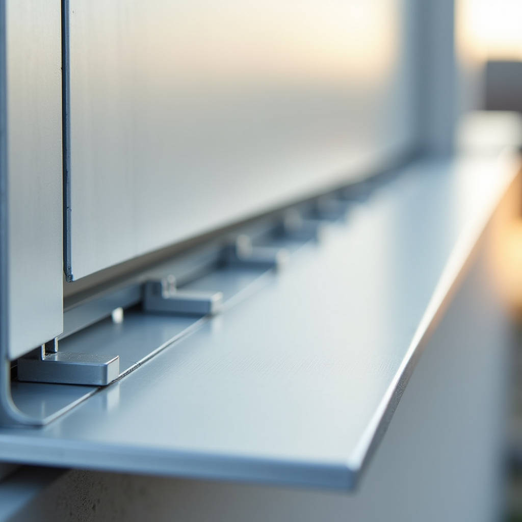
When a curtain wall contractor calls at 7:30 a.m. asking why water is pooling behind the spandrel zone, the conversation rarely starts with the panel itself. It starts with the joint. More specifically, it starts with the aluminum flashing panel that was supposed to direct water away from the gasket line but didn't. The problem is almost never the material. It's the detail: the fold tolerance, the drip edge geometry, the clearance between the flashing hem and the pressure plate. An aluminum flashing panel in a high-rise rainscreen isn't roofing trim scaled up. It's a bespoke fabricated component that carries the same wind load, thermal movement, and drainage burden as the primary cladding. Treating it as an afterthought — a bent strip of 0.040-inch sheet stock ordered from a catalog — is how you end up with a leak that takes three scaffold drops to diagnose.
What Separates a Cladding-Grade Aluminum Flashing Panel from Roofing Trim
Walk through any metal roofing supply aisle and you'll find aluminum flashing rolls in 0.010-inch to 0.019-inch thicknesses. These products serve residential roofing well. They're easy to hand-bend, they shed water at a 4:12 pitch, and they cost pennies per linear foot. But a rainscreen facade on a 20-story commercial building is a different animal. The aluminum flashing panel integrated into a unitized curtain wall system must perform three jobs simultaneously: it drains bulk water, it resists wind-driven pressure differentials, and it accommodates inter-story drift without buckling or tearing away from its anchor points.
The gauge difference is the first filter. Cladding-grade flashing panels start at 0.063 inch (1.6 mm) and more commonly land at 0.080 inch (2.0 mm) or 0.100 inch (2.5 mm) for exposed conditions. Below that threshold, the panel cannot hold a crisp hem, cannot span between clip centers without oil-canning, and cannot withstand the cyclic negative pressure that peels poorly anchored flashing away from the wall. The ASTM E330 static pressure test and ASTM E331 dynamic water penetration test don't care whether the component is called a "flashing" or a "panel." If it fails, the whole assembly fails.
Material Specification: Alloy, Temper, and Why 3003-H14 Dominates
The aluminum flashing panel market splits into two camps: those who specify the alloy and those who accept whatever the fabricator stocks. The latter group gets 1100-O aluminum — commercially pure, dead soft, easy to form, and utterly wrong for any application where the flashing must hold its shape under thermal cycling. 1100-O yields at roughly 5 ksi (34 MPa). A 3003-H14 sheet yields at 21 ksi (145 MPa). That's a fourfold difference in resistance to permanent deformation.
3003-H14 has become the default for architectural flashing because it balances formability with strength. The manganese alloying (1.0-1.5%) provides enough work-hardening capacity to hold a tight bend radius without cracking, while the H14 strain-hardened temper delivers the stiffness needed for flatness across a 4-foot panel width. For marine or heavy-industrial environments, 5052-H32 steps in with superior salt-spray resistance, though at a higher material cost and slightly reduced formability. The table below summarizes the practical differences:
| Alloy & Temper | Yield Strength (ksi) | Typical Thickness Range | Corrosion Resistance | Formability | Recommended Application |
|---|---|---|---|---|---|
| 1100-O | 5 | 0.032" – 0.063" | Moderate | Excellent | Residential roofing trim only |
| 3003-H14 | 21 | 0.063" – 0.125" | Good | Very Good | Commercial rainscreen flashing |
| 5052-H32 | 28 | 0.063" – 0.125" | Excellent (marine-grade) | Good | Coastal / chemical exposure |
| 6061-T6 | 40 | 0.080" – 0.125" | Good | Poor (cracks at tight radii) | Structural sub-girts, not flashing |
Fabricators like Futeng® regularly stock 3003-H14 coil in widths up to 60 inches specifically for flashing panel production, recognizing that lead times collapse when the alloy isn't sitting on the floor. For projects specifying PVDF coatings, the coil is pre-treated with a chrome-phosphate conversion coating before the Kynar 500® or Hylar 5000® topcoat is applied — a sequence that demands clean alloy chemistry to avoid adhesion failures.
Coating Systems and the 20-Year Color Shift Nobody Budgets For
The finish on an aluminum flashing panel isn't decorative. It's the primary defense against pitting corrosion, and it's the surface that determines whether the flashing matches the adjacent cladding or announces itself as a mismatched afterthought. Three coating tiers dominate the specification landscape:
Polyester (SP): Applied at 0.8-1.0 mil dry film thickness (DFT). Acceptable for interior soffit flashing or fully sheltered conditions. Expect noticeable chalking and 5-8 Delta E color shift within 5 years of exterior exposure. Cost is low; long-term appearance is not.
PVDF (Kynar 500® / Hylar 5000®): Applied at 1.2-1.5 mil DFT, typically as a two-coat system (primer + color coat) or three-coat for metallic finishes. This is the industry benchmark for architectural aluminum. AAMA 2605 compliance requires 10-year South Florida exposure testing with less than 5 Delta E color change. When a project specifies a 20-year finish warranty on the curtain wall, the aluminum flashing panel must carry the same PVDF system — otherwise the warranty boundary creates a maintenance liability.
FEVE (Fluoroethylene Vinyl Ether): Applied at 1.5-2.0 mil DFT. FEVE resins offer gloss retention and chemical resistance comparable to PVDF but with the added ability to cure at ambient temperature, making field touch-up more practical. The cost premium is 15-25% over PVDF, but for projects within 500 meters of breaking surf, the extra corrosion budget often pays for itself within the first maintenance cycle.
AAMA 2605 remains the governing standard for high-performance architectural coatings on aluminum. The specifier should confirm that the coating applicator is AAMA-certified and that each batch of finished flashing panels ships with a retention sample for the project file. AAMA certification directories provide current applicator listings.
Drainage Geometry: The 15-Millimeter Rule and Why It Matters
Water doesn't compress. In a rainscreen cavity, the pressure equalization chamber behind the cladding panel is designed to neutralize the kinetic energy of wind-driven rain. But the aluminum flashing panel at the floor line — the horizontal firestop and drainage plane — must still evacuate the water that enters the cavity through imperfect joints, weeps, and condensation. The geometry of that flashing determines whether water drains or ponds.
The critical dimension is the vertical upstand leg at the rear of the flashing. In North American practice, this leg must rise a minimum of 15 mm (0.59 inch) above the finished drainage plane to prevent water from backing up under wind pressure differentials. European practice, following EN 12152, often specifies 20 mm for exposed conditions. The difference isn't arbitrary — it reflects the higher average wind speeds and driving rain indices common in North Atlantic-facing facades.
The second critical dimension is the drip edge return. A flashing panel that terminates in a flat hem will allow water to track back along the underside via surface tension. A properly detailed drip edge incorporates a 10-12 mm downward return with a 3-4 mm outward kick at the bottom edge. This profile breaks the capillary path and forces water to detach and fall into the gutter or secondary drainage channel below. The cost of adding this return is one additional brake press stroke. The cost of omitting it is a water stain trail that runs the full height of the spandrel zone.
Thermal Movement: Why a 3-Meter Flashing Panel Grows 4.5 Millimeters
Aluminum expands at roughly 2.4 × 10⁻⁵ per degree Celsius. For a 3,000 mm aluminum flashing panel subjected to a 60°C temperature swing (from -10°C winter night to +50°C summer solar gain), the linear expansion is:
3,000 mm × 2.4 × 10⁻⁵ × 60 = 4.32 mm
That's nearly half a centimeter of movement that the anchoring system must accommodate without buckling the panel or tearing the fasteners. The standard detail for managing this movement is the slotted clip: a continuous aluminum extrusion or stainless steel bracket with an elongated hole that allows the flashing to slide longitudinally while restraining it in the transverse and normal directions.
The slot length is calculated as the expected movement plus a 3 mm safety margin at each end. For a 3-meter panel, that means a minimum 11 mm slot. The fastener is a #12 or #14 stainless steel self-tapping screw with a bonded EPDM washer, torqued to 35-40 inch-pounds — tight enough to prevent flutter, loose enough to permit sliding. Overtorquing is the most common field error. A screw driven to 60 inch-pounds crushes the EPDM washer and locks the panel solid, at which point thermal stress has nowhere to go except into the panel itself. The result is an oil-can pattern that appears within the first seasonal cycle.
Wind Load Design: The Suction Side Is the Real Threat
Most people think about wind pushing panels inward. But the governing load case for an aluminum flashing panel is outward suction. When wind flows across a building face, the Bernoulli effect generates negative pressure that can exceed the positive pressure on the windward side by a factor of 1.5 or more, particularly at corners, parapets, and eaves — precisely where flashing panels are concentrated.
ASCE 7-22 provides the methodology for calculating design wind pressures based on building geometry, exposure category, and topographic factors. For a typical mid-rise building in Exposure B (suburban/urban terrain), the corner zone negative pressure at the roof parapet can reach -45 psf (-2.15 kPa) under ultimate wind speeds. The aluminum flashing panel must be anchored to resist this load with a safety factor of 2.0 for yielding and 3.0 for pull-out.
Clip spacing drives the calculation. A 0.080-inch (2.0 mm) 3003-H14 flashing panel spanning 24 inches between clips can resist roughly 55 psf before the onset of permanent deformation. Reduce the spacing to 16 inches, and the capacity jumps to approximately 85 psf. The table below provides a practical reference for specifiers:
| Panel Thickness | Clip Spacing (in) | Approx. Allowable Suction (psf) | Typical Application |
|---|---|---|---|
| 0.063" (1.6 mm) | 16 | 45 | Low-rise sheltered facades |
| 0.080" (2.0 mm) | 24 | 55 | Mid-rise general conditions |
| 0.080" (2.0 mm) | 16 | 85 | Corner zones / parapets |
| 0.100" (2.5 mm) | 24 | 90 | High-rise exposed conditions |
| 0.125" (3.0 mm) | 24 | 130 | Coastal / hurricane zones |
These values assume 3003-H14 alloy and a maximum deflection limit of L/120. For projects requiring full structural calculations, the fabricator should provide engineering stamped shop drawings that include clip reaction loads for the backup structure. The ASCE 7-22 standard is the authoritative reference for wind load determination in the United States.
Fabrication Tolerances That Separate a Watertight Flashing from a Callback
Field measurements always contain errors. The question is whether the aluminum flashing panel can absorb those errors without compromising performance. The answer depends on the fabrication tolerances specified in the submittal package.
A well-written specification for architectural flashing panels references the tolerances in AAMA 609.1 for formed aluminum components. The key numbers: overall length ±1/16 inch (±1.6 mm), bend angle ±1 degree, and flatness within 0.5% of the panel dimension. On a 10-foot panel, that's a maximum deviation of 0.6 inch from a true plane. Anything beyond that creates a visible wave that catches light and signals poor workmanship to anyone standing at grade.
But the tolerance that matters most is the hem gap — the distance between the folded return and the panel face. A properly formed hem on 0.080-inch material should have a gap of 0.080 to 0.100 inch, just enough to slide over the clip leg without binding. Too tight, and the installer will force it, deforming the panel edge. Too loose, and wind-driven vibration will rattle the flashing against the clip, eventually wearing through the coating at the contact point. This is the kind of detail that never appears on a catalog page but determines whether a flashing panel performs for 5 years or 30.
Installation Sequence: Why Flashing Goes On Before the Panel Above
The single most common sequencing error on a rainscreen job is installing the upper cladding panel before the horizontal aluminum flashing panel at the floor line. The logic seems sound: work from the top down so you're not leaning over finished work. But the physics of water drainage doesn't care about installer convenience.
The correct sequence is bottom-up for flashing: install the horizontal flashing at Level 2, then install the cladding panels at Level 2, then move to the flashing at Level 3, and so on. This ensures that each flashing panel laps over the panel below it — a shingle-lap condition that drains water outward at every horizontal joint. When the sequence is reversed, the flashing must be slid behind an already-installed panel, creating a blind lap that the installer cannot verify. The result is a reverse shingle that directs water into the cavity instead of out of it.
For unitized curtain wall systems, the aluminum flashing panel is typically pre-installed in the factory as part of the unit frame. This approach offers superior quality control — the flashing is installed on a jig table, not from a swing stage — but it demands precise coordination between the flashing fabricator and the unit manufacturer. The flashing panel dimensions must account for the unit joint gap, the stack tolerance of the floor slabs, and the live-load deflection of the slab edge. A 5 mm discrepancy at the flashing level translates to a 15 mm gap three floors up, and by then the fix is a custom filler piece that nobody wants to explain to the architect.
Supply Chain Realities: Lead Times, Coil Availability, and the Custom Color Trap
A standard mill-finish aluminum flashing panel in 3003-H14 can ship in 2-3 weeks from a well-stocked fabricator. Add a PVDF coating in a stock color — Silver Metallic, Bone White, or Anodic Clear — and the lead time extends to 4-5 weeks. Specify a custom color match, and the timeline stretches to 8-10 weeks because the coil coater must schedule a dedicated run, and the minimum order quantity for a custom PVDF coil is typically 500-1,000 square meters.
This is where project schedules unravel. The general contractor orders the custom-color curtain wall panels 16 weeks ahead, but the aluminum flashing panel doesn't hit the submittal log until week 8, and by then the custom coating lead time pushes delivery past the enclosure deadline. The fix is to treat flashing panels as a critical-path procurement item, not a miscellaneous metal afterthought. On projects where Futeng® supplies both the primary cladding panels and the flashing components, the color-matched coil is ordered in a single batch, eliminating the risk of batch-to-batch color variation and ensuring that the flashing arrives on the same truck as the wall panels.
The Metal Construction Association (MCA) publishes technical bulletins on coil coating and flashing design that are useful references for specifiers building a submittal review checklist. The ASTM International database also provides the full text of relevant standards including ASTM B209 for aluminum sheet and ASTM E2112 for flashing installation.
Quality Verification: What to Check Before the Scaffold Comes Down
The window for catching flashing defects is narrow. Once the cladding panels are installed above and below, the horizontal flashing is buried in the cavity, accessible only by removing finished work. A structured inspection before panel closure should verify at least the following:
- Lap direction: Every horizontal flashing joint must lap shingle-style — upper panel over lower panel. A single reversed lap will funnel water into the cavity.
- Fastener torque: Spot-check 10% of fasteners with a calibrated torque wrench. Any screw exceeding 45 inch-pounds on a slotted clip is locked and must be backed off.
- End dam height: At the termination of each flashing run, the end dam must rise at least 15 mm above the drainage plane. Site-cut ends without end dams are a guaranteed leak path.
- Coating integrity: Scan for scratches, particularly at cut edges and fastener penetrations. Any breach through the PVDF topcoat to bare metal requires a two-part touch-up kit applied within 24 hours.
- Clearance at movement joints: At building expansion joints, the flashing must be discontinuous with a minimum 25 mm gap, bridged by a flexible silicone bellows or a sliding cover plate.
A single-page inspection checklist, signed by the installer's supervisor and the GC's enclosure consultant, costs 15 minutes per floor and saves months of post-occupancy leak investigation. The National Fenestration Rating Council and related industry bodies continue to emphasize the importance of field verification for all components in the building envelope drainage chain.
An aluminum flashing panel is not a commodity. It's a fabricated architectural component that carries the same performance burden as the most visible element of the facade. The difference between a flashing that drains and a flashing that leaks is rarely the material. It's the alloy selection, the coating specification, the bend tolerance, the clip slot length, the fastener torque, the lap direction, and the inspection discipline. Get those six things right, and the flashing does its job silently for the life of the building. Get one wrong, and the 7:30 a.m. phone call is a matter of time.