Aluminum Drip Edge Specification for Solid Aluminium Cladding Facades What Engineers Get Wrong
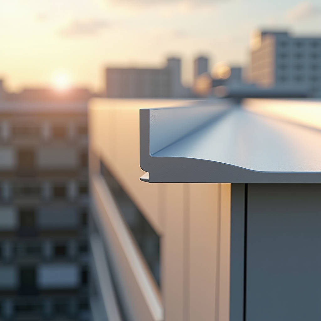
When a commercial cladding system meets the roof edge, water doesn't care about your contract terms. It follows physics. A poorly specified drip edge—or worse, one cobbled together from leftover flashing—can funnel water behind the facade, saturate insulation, and trigger a cascade of failures that no warranty will cover. The Aluminum Drip Edge is that narrow strip of metal at the roofline that most project specs treat as an afterthought, yet it carries an outsized responsibility: breaking the capillary bond between rainwater and the building envelope. For architects and facade engineers working with solid aluminium cladding panels, the drip edge is not just a roofing accessory. It's the termination detail that defines whether water drains outward or migrates inward. This article examines the technical demands placed on Aluminum Drip Edge profiles in high-performance facade systems—covering alloy selection, profile geometry, coating compatibility, and the installation tolerances that separate a dry building from a liability.
Why the Drip Edge Matters More When the Facade Is Solid Aluminium
Solid aluminium cladding panels—typically 2.0mm, 2.5mm, or 3.0mm thick sheets with PVDF or powder-coated finishes—create a relatively non-porous facade surface. Water that strikes the building face sheets down the wall and collects at horizontal joints, window heads, and parapet caps. But the roof-to-wall junction is the critical interface. Here, the Aluminum Drip Edge performs three functions simultaneously: it directs roof runoff away from the fascia, it shields the top edge of the cladding panel from direct rain exposure, and it provides a clean visual termination line.
The problem arises when specifiers treat the drip edge as a generic commodity item. A standard residential drip edge—often 0.015" or 0.019" gauge aluminium with a simple hem—was never designed to coordinate with the thermal movement, wind load deflection, and drainage plane requirements of a commercial solid aluminium facade. The coefficient of thermal expansion for aluminium is roughly 2.3 × 10⁻⁵ per °C. A 3-meter length of drip edge can expand and contract by 2–3mm over a 40°C temperature swing. If the profile is rigidly fastened to both the cladding substrate and the roof deck without accommodation for differential movement, you get buckling, fastener pull-through, or a gap that opens at the worst possible moment.
Alloy and Temper: What the Gauge Number Doesn't Tell You
Many project specifications reference "aluminum drip edge" without calling out an alloy designation. This is a mistake. The most common alloys used in formed drip edge profiles are 3003-H14, 3105-H14, and 5052-H32. Each behaves differently under brake forming and long-term exposure.
3003-H14 is the workhorse. It offers good formability, adequate strength for most profiles, and solid corrosion resistance. 3105-H14 provides slightly higher tensile strength—around 150 MPa versus 130 MPa for 3003—making it a better choice for longer spans or profiles with deeper leg dimensions. 5052-H32 delivers the highest strength of the three, with tensile values around 210 MPa, but it's also more expensive and harder to form into complex hem profiles without cracking.
For commercial cladding projects, 3003-H14 or 3105-H14 in 0.032" (0.81mm) or 0.040" (1.02mm) thickness is the practical sweet spot. Anything thinner risks deformation during installation or wind-driven rain events. Anything thicker becomes difficult to form cleanly and adds unnecessary cost. The key is to specify the alloy and temper explicitly in the submittal package, not just "aluminum drip edge."
Profile Geometry: The Difference Between a Drip and a Trickle
The shape of the drip edge profile determines whether water actually detaches from the metal surface or clings to it and wicks backward. This is governed by the drip leg angle, the hem configuration, and the overall projection beyond the fascia plane.
A properly designed Aluminum Drip Edge for commercial cladding should have a drip leg that kicks outward at a minimum 15° angle from vertical. This creates a sharp break point where surface tension can no longer hold the water film against the metal. The hem—a folded return at the bottom edge—adds stiffness and provides a secondary drip point. A single hem is standard; a double hem adds rigidity but may trap debris in certain environments.
The projection beyond the fascia should be at least 25mm (1 inch) for low-rise buildings and 40mm (1.5 inches) for mid-rise structures where wind can drive rain upward and sideways. On high-rise projects, the drip edge often needs to be integrated with a pressure-equalized rainscreen design, which means the profile must accommodate a ventilation gap behind the cladding while still providing positive drainage at the roof line.
Coating Compatibility: PVDF, Powder, and the Galvanic Question
When the Aluminum Drip Edge is installed adjacent to solid aluminium cladding panels with a PVDF (polyvinylidene fluoride) coating—typically a 70% PVDF resin system like Kynar 500® or Hylar 5000®—the drip edge should ideally carry the same coating system. This isn't just about aesthetics. A color-matched drip edge with the same PVDF formulation ensures identical fade and chalk resistance over the 20- to 30-year service life expected of a commercial facade.
The standard PVDF coating specification for architectural aluminium is AAMA 2605, which requires a minimum total dry film thickness of 30 microns (1.2 mils) in a three-coat system (primer, color coat, clear coat). A two-coat system at 25 microns minimum meets AAMA 2604, which is acceptable for drip edges on less visible roof areas but may show color shift earlier than the adjacent wall panels.
Powder coating to AAMA 2604 standards is an alternative, particularly for projects where the drip edge color is a custom match. However, powder coat on thin-gauge formed profiles can be prone to chipping at the hem fold if the coating is applied before forming. Post-forming coating is ideal but logistically difficult for long linear profiles. The practical solution is to specify a pre-coated coil with a PVDF system, then form the profile—accepting minor micro-cracking at the bend radii, which is normal and does not compromise corrosion resistance on 3000-series alloys.
Galvanic corrosion is a concern when aluminium drip edges contact dissimilar metals. Copper gutters, steel fasteners, or zinc flashing can all drive corrosion on the aluminium if a moisture bridge exists. Stainless steel fasteners (300 series) are the safest choice. If steel framing is unavoidable, a separating tape or gasket at the contact point is mandatory.
| Coating System | Standard | DFT (microns) | Color Retention (10 yrs) | Typical Application |
|---|---|---|---|---|
| PVDF 70% (3-coat) | AAMA 2605 | 30–35 | ΔE ≤ 5 | Premium facade, visible drip edges |
| PVDF 70% (2-coat) | AAMA 2604 | 25–30 | ΔE ≤ 5 | Standard commercial, semi-visible |
| Polyester Powder | AAMA 2604 | 60–80 | ΔE ≤ 8 | Budget-sensitive, less UV exposure |
| Mill Finish (3003-H14) | N/A | N/A | N/A (oxidizes naturally) | Concealed or industrial applications |
| Anodized (AA-M10C22A31) | AAMA 611 | 10–20 (anodic layer) | ΔE ≤ 10 | Architectural, uniform matte finish |
Wind Load and Fastener Spacing: Engineering the Attachment
Wind uplift at the roof perimeter is significantly higher than at the field of the roof. The Aluminum Drip Edge sits right in this high-pressure zone. ASCE 7-22 provides the methodology for calculating edge-zone wind pressures, and for most commercial buildings in the U.S., the design uplift pressure at the roof perimeter ranges from 1.5 kPa to 4.0 kPa (30 to 85 psf), depending on the building height, exposure category, and geographic location.
Fastener spacing for the drip edge must be calculated, not guessed. A typical 0.032" 3003-H14 drip edge with a 50mm (2-inch) vertical leg, fastened with #10 stainless steel screws at 300mm (12-inch) centers, can resist approximately 2.2 kPa of uplift before the metal begins to deform around the fastener heads. If the calculated uplift is higher, the options are: reduce fastener spacing to 200mm (8 inches), increase the material thickness to 0.040", or switch to 5052-H32 alloy.
The fastener type matters as much as the spacing. Pancake-head screws with a neoprene washer provide a larger bearing surface and a watertight seal. Standard hex-head screws without washers concentrate stress and create leak paths. For solid aluminium cladding systems where the drip edge fastens into the cladding substrate rather than the roof deck, the pull-out strength of the substrate must be verified. Thin-gauge metal studs may require rivet nuts or toggle anchors to achieve the necessary pull-out values.
Integration with the Rainscreen Cavity
Modern commercial cladding increasingly uses a rainscreen principle: an outer layer of solid aluminium panels, a ventilated air cavity, and an inner weather barrier. The Aluminum Drip Edge at the top of the wall must be detailed to allow air to exit the cavity while preventing water from entering it.
The standard detail places a perforated closure profile behind the drip edge, allowing cavity ventilation while blocking insects and debris. The perforations should provide a minimum free area of 50% of the cavity cross-section to avoid restricting airflow. If the drip edge is installed tight against the cladding without a ventilation gap, the cavity becomes a dead air space, and condensation can accumulate on the back of the panels during cold weather.
At the same time, the drip edge must extend far enough down the wall to cover the top edge of the cladding panel and any horizontal joint below it. A minimum 75mm (3-inch) vertical overlap is recommended. This overlap should include a sealant joint at the top of the cladding panel—not to stop water (the rainscreen principle assumes some water will get behind the panel) but to act as a pressure-equalization barrier that reduces the force driving water into the cavity.
Thermal Bridging and the Often-Ignored Energy Code
The drip edge is a continuous metal element that bridges the roof insulation and the exterior wall. In colder climates, this creates a thermal bridge that can drop the interior surface temperature at the roof-wall junction below the dew point, leading to condensation and potential mold growth inside the building.
ASHRAE 90.1 and the International Energy Conservation Code (IECC) increasingly require continuous insulation at the building envelope. The drip edge attachment must be detailed with a thermal break—typically a 6mm to 10mm layer of rigid PVC or polyamide isolator strip—between the metal drip edge and the structural substrate. This is especially important on projects targeting LEED or Passive House certification, where thermal bridging at linear transitions is modeled and penalized.
The thermal break adds cost and complexity, but on a high-performance building, it's no longer optional. The energy model will flag the junction, and the building envelope consultant will require it. Specifying the drip edge with an integral thermal break from the outset avoids a costly redesign during the shop drawing phase.
Fabrication Tolerances and Quality Control
Aluminum Drip Edge profiles are typically roll-formed from coil stock or brake-formed in sections. Roll forming produces consistent profiles in long lengths—up to 6 meters (20 feet) or more—with tight dimensional tolerances, typically ±0.5mm on leg dimensions and ±1.5mm on overall length. Brake forming is more flexible for custom profiles but introduces variability, especially on longer pieces where the bend angle can wander.
For commercial cladding projects, the specification should require that drip edge profiles be fabricated from a single length of material per building elevation where possible. Field-spliced drip edges create joints that must be lapped and sealed, and every lap is a potential leak point. If splices are unavoidable, they should be lapped a minimum of 100mm (4 inches) in the direction of water flow and bedded in a high-quality polyurethane sealant.
Inspection of incoming drip edge material should verify the alloy, temper, thickness, and coating specification against the submittal. A mill test report (MTR) for the coil stock is the gold standard. For PVDF-coated material, the coating supplier's certification confirming compliance with AAMA 2605 or 2604 should be on file before the material is installed.
When the Drip Edge Meets the Cladding: The Critical Interface Detail
The junction between the Aluminum Drip Edge and the solid aluminium cladding panel is where most failures originate. The cladding panel typically terminates at the roof line with a horizontal break—a Z-girt or hat channel that supports the top edge of the panel. The drip edge must overlap this termination by enough margin to account for the panel's thermal movement and any live-load deflection of the roof structure.
One common mistake is fastening the drip edge through the cladding panel itself. This locks the two elements together and transfers roof movement into the cladding, which can cause oil-canning or fastener fatigue. The correct detail fastens the drip edge to the structural substrate independently of the cladding, with a slip joint or flexible sealant connection between the two.
Another detail that gets overlooked is the end-dam at the drip edge termination. At the gable ends or where the drip edge meets a parapet wall, water running along the drip edge can spill off the end and onto the wall below. A small end-dam—a turned-up tab at the end of the drip edge—redirects water forward and away from the wall. This is a minor fabrication step that costs almost nothing but prevents staining and water damage at a highly visible location.
For projects specifying solid aluminium cladding from manufacturers like Futeng®, the drip edge can often be supplied as part of the same package, with matching PVDF coating and coordinated shop drawings. This eliminates the finger-pointing that occurs when the cladding supplier and the roofing contractor each blame the other for a leak at the interface.
Specifying the Right Drip Edge for Your Project
A tight specification for an Aluminum Drip Edge on a commercial cladding project should include the following minimum elements: alloy and temper (e.g., 3003-H14 or 3105-H14), material thickness (0.032" minimum), profile geometry with a defined drip leg angle and hem configuration, coating system (PVDF to AAMA 2605 or 2604 with color code), fastener type and spacing calculated for the project's wind uplift, thermal break requirement per the energy model, and fabrication tolerances with inspection criteria.
Leaving any of these elements to the contractor's discretion invites substitution with a lower-grade product that meets the letter of the spec but not the intent. The cost difference between a properly specified drip edge and a generic one is measured in cents per linear foot. The cost of a water-damaged facade assembly is measured in tens of thousands of dollars and months of litigation.
The Aluminum Drip Edge is a small component in the building envelope, but it sits at the most vulnerable intersection: where the roof drainage plane meets the wall cladding plane. Getting it right requires attention to alloy selection, profile geometry, coating compatibility, structural attachment, thermal performance, and interface detailing. None of these are particularly complex in isolation, but together they demand a level of coordination that doesn't happen by accident. It happens when the specification is written with the same rigor applied to the cladding panels themselves.
For further technical guidance, refer to the AAMA 2605 specification for coating performance, ASTM B209 for aluminium sheet and plate standards, and the NRCA Roofing Manual for drip edge installation best practices. The ASCE 7-22 standard provides the wind load calculation methodology that should drive fastener spacing decisions, and ASHRAE 90.1 addresses the thermal bridging requirements that increasingly govern envelope detailing.