Aluminum Sill Panel Engineering for Drained Rainscreen Facades and Window Water Management
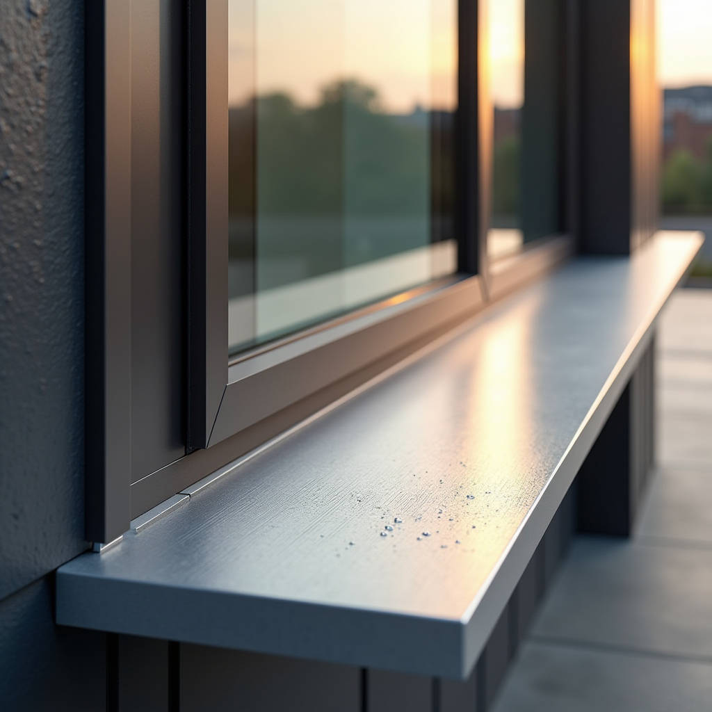
Water penetration at window perimeters remains one of the most persistent and costly failure points in commercial building envelopes. An Aluminum Sill Panel, when properly specified and integrated into the facade system, functions as the primary drainage plane at the base of window openings — directing bulk water outward, protecting the rough opening substrate, and maintaining the thermal and structural integrity of the wall assembly. Unlike field-fabricated flashing made from coil stock that relies on jobsite workmanship, a purpose-engineered Aluminum Sill Panel manufactured from solid aluminum sheet (typically 2.0mm to 3.0mm thickness) with factory-applied PVDF or powder coating delivers predictable, repeatable performance across hundreds of openings on a single project. For general contractors and facade subcontractors managing tight schedules and stricter water testing protocols, understanding the material specifications, drainage mechanics, and installation sequencing of these panels has become essential to passing AAMA 501.2 and ASTM E1105 hose tests without costly rework.
What an Aluminum Sill Panel Actually Does in a Drained Wall System
In a drained and back-ventilated rainscreen assembly, the Aluminum Sill Panel serves a role that goes well beyond cosmetic trim. It acts as the horizontal water control layer at the sill — the point where gravity-fed water traveling down the cavity must be intercepted and redirected to the exterior. The panel typically includes an upturned back leg that integrates with the water-resistive barrier (WRB) or air barrier membrane, end dams at both jambs to prevent lateral water migration into the rough opening, and a sloped sill surface that projects water outward past the face of the cladding below.
The geometry matters. A sill panel with a minimum 5-degree outward slope, a drip edge with a 10mm to 15mm projection beyond the cladding plane, and welded or mechanically fastened end dams creates a three-sided containment that channels water to a single exit path. When these details are field-fabricated, consistency suffers. Factory-engineered Aluminum Sill Panel solutions eliminate the variability because each unit arrives with end dams pre-welded, slopes pre-formed, and coating fully cured — leaving the installer to focus on proper shimming, anchoring, and sealant joint placement.
Material Selection: Solid Aluminum Sheet vs. Extruded Sill Profiles
Both solid aluminum sheet and extruded aluminum profiles are used for sill applications, but they serve different performance requirements. Solid sheet-based sill panels — fabricated from 5052-H32 or 6061-T6 aluminum alloy in 2.0mm, 2.5mm, or 3.0mm thicknesses — offer greater design flexibility for custom geometries, wider widths, and integrated end dam welding. Extruded sill profiles, typically 6063-T5 alloy with wall thicknesses around 1.5mm to 2.0mm, provide consistent cross-sections and are well-suited for standardized window sizes in residential and light-commercial work.
The critical distinction for specifiers is this: solid sheet panels can be fabricated to match the exact cavity depth, sill slope, and end dam height required by the project's specific rainscreen geometry, while extruded profiles lock the project into a fixed cross-section. For complex commercial facades with variable cavity depths, deep window reveals, or integration with unitized curtain wall systems, solid aluminum sill panels offer the dimensional flexibility that extruded stock profiles cannot match.
| Property | Solid Aluminum Sheet Sill Panel (2.5mm 5052-H32) | Extruded Aluminum Sill Profile (6063-T5) |
|---|---|---|
| Alloy & Temper | 5052-H32 (marine grade, superior corrosion resistance) | 6063-T5 (good extrudability, moderate strength) |
| Typical Thickness | 2.0mm – 3.0mm | 1.5mm – 2.0mm |
| Custom Geometry | Full flexibility — slope, depth, end dam height all adjustable | Fixed die profile; changes require new extrusion die |
| End Dam Integration | Pre-welded at factory, watertight | Typically requires separate end caps or sealant-dependent joints |
| Maximum Panel Length | Up to 4,000mm (transport-limited; longer with splices) | Typically 6,000mm+ (extrusion press limited) |
| Coating Options | PVDF (AAMA 2605), powder coat (AAMA 2604), anodized | Powder coat, anodized; PVDF less common |
| Typical Application | Commercial rainscreen, unitized curtain wall, high-rise | Residential windows, light commercial, standardized openings |
For projects in coastal or industrial environments, the alloy choice becomes particularly important. 5052-H32 contains approximately 2.5% magnesium and 0.25% chromium, giving it excellent resistance to chloride-induced pitting — a meaningful advantage over 6063-T5 in marine-exposed facades. Fabricators such as Futeng® supply solid aluminum sill panels in 5052 alloy with PVDF coating systems that meet the 20-year film integrity requirements of AAMA 2605, a specification point worth verifying when reviewing submittals for oceanfront projects.
Coating Systems and Long-Term Weathering Performance
The coating on an Aluminum Sill Panel endures some of the harshest micro-conditions on any facade. Unlike vertical wall panels that primarily face UV exposure, sill panels are subjected to standing water, concentrated wind-driven rain, freeze-thaw cycling, and in cold climates, direct contact with de-icing salts tracked onto ledges. A coating system that performs adequately on a vertical wall may fail prematurely on a horizontal sill surface if not properly specified.
PVDF (polyvinylidene fluoride) coatings meeting AAMA 2605 remain the benchmark for architectural aluminum in demanding sill applications. The 70% PVDF resin system — typically Kynar 500® or Hylar 5000® — delivers a minimum 30-micron total dry film thickness in a three-coat system (primer, color coat, clear coat). The clear coat matters: it provides the UV-blocking layer that protects the color coat from chalking and fading. For sill panels, a three-coat system is strongly recommended over a two-coat alternative because the horizontal orientation increases annual UV dosage compared to vertical surfaces at most latitudes.
Powder coatings conforming to AAMA 2604 offer a lower-cost alternative with good performance in less aggressive environments. The key limitation is gloss retention and color stability under extended UV exposure — AAMA 2604 powder coatings typically show measurable fade within 5 to 7 years on horizontal surfaces, compared to 15 to 20 years for AAMA 2605 PVDF. For budget-sensitive projects in inland locations with moderate sun exposure, a high-quality polyester powder coat may be an acceptable trade-off, but the specifier should understand the maintenance recoating implications over the building's service life.
Water Management: The Mechanics of Sill Pan Drainage
Effective sill pan drainage depends on three interconnected details: the slope, the end dams, and the integration with the WRB below. When any one of these fails, water finds its way into the rough opening — and by the time the staining appears on interior drywall, the damage to sheathing, insulation, and framing has often been underway for months.
The sill slope is the first line of defense. Building science research from the Building Science Corporation has consistently demonstrated that a minimum 6% slope (roughly 3.5 degrees) is required to overcome water surface tension and ensure positive drainage on metal sill surfaces. Flatter slopes allow water to bead and pool, and pooled water eventually finds pinhole defects in welds, sealant joints, or coating discontinuities. A 6% slope translates to approximately 6mm of fall across a 100mm sill depth — a dimension that must be accounted for in the rough opening framing and shimming plan.
End dams prevent the most common sill failure mode: lateral water migration into the jamb cavities. A properly detailed end dam extends at least 25mm up the jamb face and is continuously welded to the sill pan body, not simply sealed with field-applied sealant. Sealant-only end dams are a common source of failure because differential thermal movement between the aluminum sill and the adjacent jamb material eventually breaks the sealant bond. Factory-welded end dams, ground smooth and coated as part of the panel's finish system, eliminate this vulnerability.
The back leg upturn — typically 25mm to 50mm high — must integrate with the wall's WRB in a shingle-lap fashion: the WRB laps over the back leg so that any water running down the wall is directed onto the sill pan surface, not behind it. This detail requires coordination between the sill panel installer and the air barrier contractor, and it is one of the most frequently missed items in jobsite quality control inspections.
Thermal Performance and Condensation Risk
Aluminum is a highly conductive material — approximately 237 W/m·K for 5052 alloy — which means an Aluminum Sill Panel that spans continuously from the exterior drip edge to the interior rough opening creates a thermal bridge. In heating-dominated climates, this thermal bridge can drop the interior sill surface temperature below the dew point, leading to condensation on the interior side of the sill during cold weather.
Two strategies address this risk. The first is a thermal break: a structural separation between the exterior and interior portions of the sill assembly, typically achieved with a low-conductivity polymer strut. This approach is common in high-performance curtain wall systems but adds cost and complexity to sill panel fabrication. The second strategy, more common in rainscreen applications, is to limit the sill panel's inward penetration — stopping the aluminum at the exterior face of the WRB and using a separate interior sill element (which may be wood, stone, or thermally broken aluminum) to finish the interior. This approach keeps the conductive aluminum entirely outside the thermal envelope and eliminates the condensation pathway.
For projects targeting Passive House or similar high-performance standards, the thermal break approach is typically required. The Passive House Institute US (PHIUS) provides guidance on thermal bridge detailing that applies directly to sill conditions. Even for conventional projects, specifiers should require a thermal analysis of the sill detail when the project is located in ASHRAE Climate Zone 5 or higher, and should verify that the interior surface temperature at the sill remains above the indoor dew point under design heating conditions.
Installation Sequencing and Trade Coordination
The Aluminum Sill Panel occupies a critical interface between multiple trades: the window installer, the air barrier contractor, the cladding installer, and the sealant applicator. Getting the sequencing right prevents rework, and getting it wrong guarantees it.
The recommended sequence for drained rainscreen installations is as follows:
- Rough opening preparation: Sheathing installed, rough opening flashed with self-adhered membrane or fluid-applied WRB, sill shimmed to achieve the design slope (minimum 6%).
- Sill panel installation: Aluminum Sill Panel set into the rough opening, back leg integrated with the WRB (WRB laps over back leg), panel mechanically fastened through the back leg or side flanges into the rough framing. Shims adjusted to maintain slope.
- Window installation: Window unit set on setting blocks on top of the sill pan, shimmed and fastened per manufacturer's instructions. The window's integral sill flange or nailing fin should lap over the sill pan's back leg, maintaining the shingle-lap drainage sequence.
- Jamb and head flashing: Jamb flashings installed, lapping over the sill pan's end dams. Head flashing installed last, lapping over the jamb flashings.
- Cladding installation: Wall cladding panels installed above and below the window, with the sill pan's drip edge projecting past the face of the cladding below by a minimum of 10mm.
- Sealant joints: Perimeter sealant applied at the window-to-sill interface, with backer rod used to control sealant depth. Sealant should not be used as the primary water barrier — it is a secondary weather seal.
This sequence places the sill pan as the first installed component in the window opening, which is the correct approach for drained systems. In practice, many projects install windows first and sill pans afterward — a sequence that compromises the shingle-lap drainage and forces reliance on sealant as the primary water barrier. General contractors should enforce the correct sequence in pre-installation meetings and verify it during in-progress inspections.
Specifying Aluminum Sill Panels for Wind Load and Structural Performance
Sill panels on high-rise buildings are subjected to significant wind pressures, particularly at building corners where pressure coefficients are highest. A sill panel that deflects excessively under wind load can crack sealant joints, deform end dam connections, and create water entry paths that worsen over time as cyclic loading fatigues the metal.
The governing standard for aluminum sill panel structural design is the Aluminum Design Manual published by the Aluminum Association, which provides allowable stress design values for various alloys and tempers. For a 2.5mm-thick 5052-H32 sill panel spanning 600mm between supports, the allowable bending stress is approximately 110 MPa, which provides adequate capacity for wind loads up to approximately 3.0 kPa design pressure (corresponding to roughly 190 km/h design wind speed at building corners, depending on exposure category and building geometry).
For projects requiring higher wind load resistance — coastal high-rises, buildings in hurricane-prone regions, or projects with unusually wide window openings — increasing the panel thickness to 3.0mm or reducing the support spacing are the primary levers available to the specifier. The panel fabricator should provide calculations or test data demonstrating compliance with the project's specified design wind loads, referenced to ASCE 7 or the applicable local building code.
Quality Control: What to Check Before Panels Leave the Factory
Factory inspection of Aluminum Sill Panel units before shipping can prevent the majority of jobsite disputes and rework. A structured QC checklist should include the following verification points:
- Dimensional accuracy: Overall length, width, back leg height, and end dam height within ±2mm of approved shop drawings. Slope angle verified with a digital protractor.
- Weld integrity: End dam welds visually inspected for full penetration, free of cracks, porosity, and undercut. Grind marks smooth and flush with adjacent surfaces.
- Coating quality: Dry film thickness measured at a minimum of five points per panel per ASTM D7091. Color and gloss verified against the approved control sample under consistent lighting conditions.
- Flatness: Panel surface free of oil-canning, buckling, or visible distortion when viewed under raking light at a 3-meter distance.
- Drainage verification: A simple water test — pouring a measured volume of water onto the sill surface and verifying that it drains completely within 30 seconds, with no ponding or leakage at end dams.
For large projects, it is standard practice to require a first-article inspection: the fabricator produces one complete sill panel unit for the specifier's review and approval before proceeding with full production. This step catches dimensional and finish issues early, when corrections are inexpensive and schedule impacts are minimal.
Cost Factors and Budgeting Guidance
The cost of an Aluminum Sill Panel is driven by four primary factors: material thickness, coating system, fabrication complexity, and quantity. A 2.5mm 5052-H32 panel with a three-coat PVDF finish, including factory-welded end dams, typically falls in the range of $45 to $75 per linear meter for moderate quantities (100 to 500 units), though this range varies significantly with project location, current aluminum market pricing, and panel geometry.
Extruded sill profiles, by comparison, may cost $25 to $40 per linear meter for standard profiles, but the cost advantage narrows or disappears when custom end dam fabrication, field welding, and touch-up coating are factored in. For projects with more than 50 window openings, the total installed cost difference between a factory-fabricated solid sheet sill panel and a field-assembled extruded solution often favors the factory approach once labor, sealant, and rework are accounted for.
The most effective way to manage sill panel costs without compromising performance is to standardize opening sizes wherever possible. Each unique sill panel dimension requires a separate fabrication setup, and the cost per unit drops significantly when identical panels are produced in quantity. Architects and design-build contractors who coordinate window schedules with sill panel fabrication early in the design phase can realize meaningful savings compared to projects where sill panel dimensions are determined by field measurements after window installation.
Common Failure Modes and How to Avoid Them
Decades of forensic investigations into window leakage have identified a consistent set of failure patterns related to sill pans. Understanding these failures is the most direct path to preventing them on your own projects.
Reverse lap at the back leg: This occurs when the WRB or window flange is installed behind the sill pan's back leg rather than lapping over it. Water running down the wall is directed behind the sill pan, into the rough opening. The fix is simple — enforce the shingle-lap sequence — but it requires the WRB contractor and window installer to understand the drainage logic, not just follow a generic detail.
Ponding water: Insufficient slope, combined with surface tension, allows water to pool on the sill surface. Pooled water accelerates coating degradation, promotes biological growth, and in freezing climates, creates ice dams that can deform the panel. The 6% minimum slope is not negotiable.
End dam sealant failure: Field-applied sealant at end dams inevitably fails due to differential movement, UV exposure, and improper surface preparation. Factory-welded end dams are the only reliable long-term solution for commercial buildings with a 50-year design life.
Galvanic corrosion: When aluminum sill panels are installed in contact with dissimilar metals — particularly copper flashing or steel fasteners — galvanic corrosion can destroy the aluminum within a few years in the presence of moisture. Stainless steel fasteners (Type 304 or 316) and isolation between aluminum and copper components are essential. The American Galvanizers Association provides detailed guidance on galvanic compatibility that applies directly to sill panel detailing.
Inadequate drip edge projection: A drip edge that does not project far enough past the cladding below allows water to wick back onto the wall surface, causing staining and potential water entry at the cladding joints below the window. A 10mm minimum projection is standard; 15mm is recommended in high-rainfall climates.
Integrating Sill Panels with Unitized Curtain Wall Systems
Unitized curtain wall systems present unique sill panel challenges because the window and wall panels arrive on site as pre-assembled units. The sill condition must be detailed at the factory, not resolved in the field. This places a premium on coordination between the curtain wall fabricator, the sill panel supplier, and the design team during the shop drawing phase.
In a typical unitized system, the Aluminum Sill Panel is integrated into the unit frame at the factory, with the sill slope, end dams, and back leg connection all pre-engineered and pre-assembled. The panel-to-panel joint at the vertical mullion between adjacent units must accommodate both thermal movement and installation tolerances while maintaining the drainage path. A common detail uses a split sill with a central splice plate, allowing each unit's sill to move independently while the splice plate maintains the water barrier.
For design-build teams working with unitized systems, the key specification point is that sill panel performance should be verified through laboratory testing of a full-scale mockup that includes the sill condition, not through isolated component testing. AAMA 501.2 hose testing on the installed mockup provides the most reliable verification that the sill detail performs as intended under simulated wind-driven rain conditions.
The specification of an Aluminum Sill Panel is ultimately a risk management decision. The incremental cost of a properly engineered, factory-fabricated sill panel with welded end dams, adequate slope, and a durable coating system is small relative to the cost of repairing water damage in a completed building. For projects where the building envelope must perform reliably for decades with minimal maintenance, the sill panel deserves the same level of attention as the curtain wall, the air barrier, and the roof membrane. Getting this detail right — through careful material selection, rigorous submittal review, and disciplined installation sequencing — is one of the highest-return investments a project team can make in long-term building performance.