Aluminum Canopy Panel Engineering for Drainage Thermal Movement and Long Term Weathering Performance
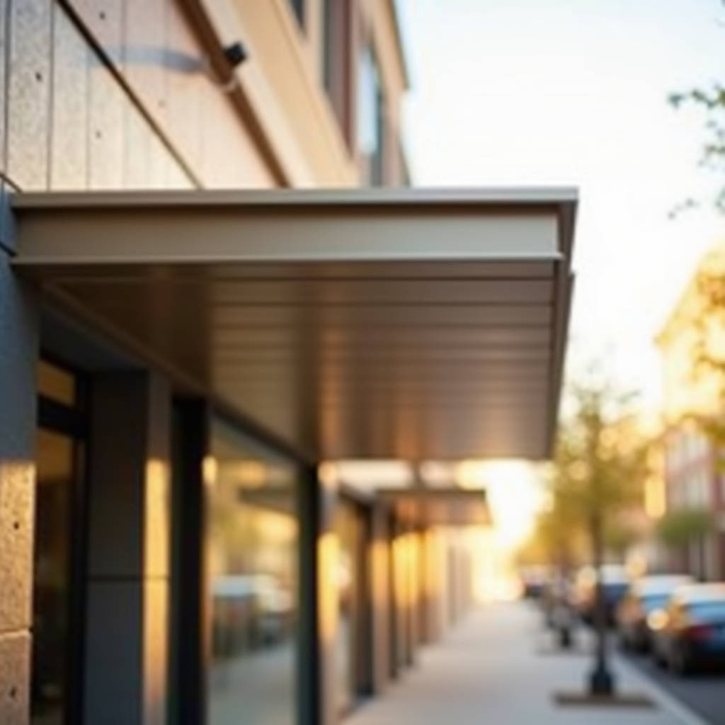
Specifying an Aluminum Canopy Panel for a commercial entrance or pedestrian walkway looks straightforward on paper. Pick a panel profile, choose a finish, detail the substructure, and move on. The reality on site is different. Water finds its way into joints that looked perfect in the shop drawing. Thermal movement that nobody accounted for causes fasteners to loosen within two seasons. A finish that held up beautifully on a vertical wall starts chalking prematurely on a horizontal canopy surface exposed to standing water and relentless UV. These failures share a common root cause: the specification process treated the canopy as just another cladding element rather than a distinct architectural component with its own set of structural, drainage, and weathering demands. This article examines the technical decisions that separate a canopy installation that performs quietly for 20 years from one that generates callbacks within 24 months.
What Makes a Canopy Panel Different from Standard Wall Cladding
A wall panel sheds water by gravity. Rain hits the surface and runs down. The panel laps over the one below it, and the drainage plane stays relatively simple. An Aluminum Canopy Panel operates under fundamentally different conditions. It sits horizontally or at a shallow slope, which means water can pool, debris can accumulate, and the panel itself becomes a catchment surface. The joint orientation that works on a vertical elevation—where panels overlap like shingles—creates a direct path for water ingress when applied to a near-flat canopy. This is why concealed-fastener canopy systems from manufacturers like McElroy Metal use interlocking profiles specifically engineered for low-slope applications. The interlock creates a mechanical barrier against water migration even when the panel surface holds standing water. The profile geometry matters. A rib height of 1.5 to 2 inches provides the necessary capillary break. Anything shallower risks water bridging across the joint under surface tension. The panel width also factors in. Narrower panels—typically 12 to 16 inches—allow for better slope control and reduce the volume of thermal expansion that any single joint must accommodate.
Material Selection: Why Solid Aluminum Outperforms Composite Alternatives in Canopy Applications
Solid aluminum sheet—specifically 2.0mm, 2.5mm, or 3.0mm 5052 or 3003 alloy—brings a set of properties to canopy design that directly address the application's unique stresses. The first is stiffness-to-weight ratio. A 2.5mm solid aluminum panel weighs approximately 6.8 kg/m², which keeps the dead load manageable while providing enough rigidity to resist oil-canning under thermal cycling. The second is corrosion resistance. The 5000-series alloys contain magnesium, which provides excellent resistance to atmospheric corrosion, particularly in coastal environments where chloride exposure is a concern. The third and often overlooked property is the material's behavior under cyclic loading. Canopies experience repeated wind uplift and downward pressure. Solid aluminum handles this fatigue loading predictably, with well-documented S-N curves that allow engineers to calculate service life with confidence. This stands in contrast to composite panels, where the core material introduces variables in long-term fatigue performance that are harder to model. For projects near saltwater, specifying 5052-H32 alloy with a minimum thickness of 2.5mm provides a conservative design basis that accounts for both structural demands and corrosion allowance over a 30-year service life.
Finish Systems for Horizontal Exposure: What PVDF Coatings Must Deliver
The coating on an Aluminum Canopy Panel faces harsher conditions than any vertical facade surface. The sun strikes it at a more direct angle for more hours of the day. Rain does not simply run off; it sits in low spots and evaporates, concentrating any contaminants. Bird droppings, tree sap, and atmospheric pollutants linger rather than washing away. These conditions demand a finish system specified for horizontal exposure. The industry benchmark is a three-coat PVDF system meeting AAMA 2605 standards. The critical specification points are resin content—minimum 70% PVDF resin by weight in the color coat—and total dry film thickness of 30-35 microns for the color coat with a 5-10 micron clear topcoat. The primer layer, typically 5-8 microns, must be a corrosion-inhibiting formulation compatible with the aluminum substrate. A two-coat system meeting AAMA 2604 may suffice for sheltered soffit applications, but for any surface that sees direct sun and weather, the three-coat 2605 specification is the minimum defensible choice. The color selection also matters for long-term appearance. Dark colors absorb more solar radiation, driving higher panel surface temperatures and accelerating any degradation mechanisms. A black canopy panel in Phoenix can reach surface temperatures exceeding 82°C (180°F). Light to medium colors—silver metallic, champagne, light bronze—reduce thermal stress on both the coating and the panel substrate.
| Coating System | Standard | PVDF Resin Content | Dry Film Thickness | Warranty Expectation | Suitable Canopy Application |
|---|---|---|---|---|---|
| 3-Coat PVDF | AAMA 2605 | ≥70% | 35-45 μm total | 20-30 years | Exposed horizontal surfaces, coastal zones |
| 2-Coat PVDF | AAMA 2604 | ≥50% | 25-30 μm total | 10-15 years | Sheltered soffits, moderate climates |
| FEVE Fluoropolymer | AAMA 2605 | N/A (FEVE resin) | 35-45 μm total | 20-30 years | Shop-applied, high-gloss requirements |
| Powder Coat (Super Durable) | AAMA 2604 | N/A (polyester) | 60-80 μm | 10-15 years | Interior canopies, non-critical exposure |
| Anodized (Class I) | AAMA 611 | N/A | 18-25 μm oxide | 10-20 years | Architectural soffits, limited color range |
Structural Engineering for Canopy Panels: Wind Load, Snow Load, and the Drainage Slope Minimum
Every canopy design must reconcile two competing requirements: the structural capacity to resist environmental loads and the geometric constraints needed for proper drainage. The International Building Code (IBC) requires canopies to be designed for wind uplift per ASCE 7, with the specific wind speed depending on the project location. A canopy in Miami-Dade County faces design wind speeds of 180 mph or higher, while a project in the Midwest may need to handle 30 psf or more of ground snow load. The panel span—the distance between supporting purlins or girts—directly determines the required panel thickness. A 2.0mm Aluminum Canopy Panel spanning 600mm between supports may be adequate for a low-wind interior application. The same panel spanning 1,200mm in a high-wind coastal zone needs to be at least 3.0mm thick, and the engineer should verify deflection limits under the specific load combination. The drainage slope is equally critical. The minimum slope for a solid metal canopy panel is 1/4 inch per foot (approximately 2%). This provides enough gradient for water to flow toward the gutter or drip edge without ponding. At slopes below 1%, surface tension and minor panel deflections can create localized ponding zones that accelerate coating degradation and promote biological growth. For long canopies exceeding 30 feet, designing the slope at 3/8 inch per foot provides a margin of safety that accounts for construction tolerances and long-term deflection under dead load.
Thermal Movement: The Joint Detail That Engineers Overlook
Aluminum expands and contracts at a rate of approximately 0.000023 meters per meter per degree Celsius. For a 10-meter-long Aluminum Canopy Panel exposed to a temperature swing of 60°C between a cold winter night and a hot summer afternoon, the total movement is about 13.8mm. If the panel is rigidly fixed at both ends, that movement has nowhere to go. The result is fastener elongation, panel buckling, or sealant failure—all of which create paths for water ingress. The correct detail provides a fixed anchor point at one end of each panel run and sliding connections at all other attachment points. The sliding connection typically uses a slotted hole in the panel clip or the substructure, with a stainless steel fastener tightened just enough to hold the panel in place while allowing longitudinal slip. The slot length must be calculated for the specific panel length and the project's design temperature range, with an additional 3mm of clearance on each side as a safety margin. For multi-panel canopy assemblies, expansion joints should be located at intervals not exceeding 8 to 10 meters. These joints require a two-piece cover plate or a purpose-designed expansion joint profile that maintains the weather barrier while accommodating the calculated movement range.
Substructure Compatibility: Galvanic Corrosion and Material Pairing
The substructure that supports an Aluminum Canopy Panel is typically steel or aluminum. Steel offers lower material cost and higher stiffness. Aluminum offers lighter weight and eliminates the galvanic corrosion risk. When steel is used, the interface between the aluminum panel and the steel support requires careful detailing. Direct contact between aluminum and carbon steel in the presence of an electrolyte—rainwater, condensation, or even high humidity—creates a galvanic cell where the aluminum acts as the anode and corrodes preferentially. The solution is a physical barrier at every contact point. This can be a neoprene or EPDM isolation pad, a nylon washer under the fastener head, or a factory-applied isolation coating on the steel member. Stainless steel fasteners (300 series) are compatible with aluminum and do not require isolation, though they should still be specified with a suitable thread-locking compound to prevent loosening under vibration and thermal cycling. The substructure design must also account for differential thermal movement between the aluminum panel and a steel support frame. Aluminum expands roughly twice as much as steel for the same temperature change. If both are rigidly connected, the differential movement can shear fasteners or distort panels. The sliding connection detail described above addresses this when the panel attachment clips allow movement relative to the substructure.
Fabrication Tolerances and Their Impact on Installation Quality
A well-engineered Aluminum Canopy Panel system can still fail if the fabrication tolerances are not controlled. The panel flatness after forming is a key quality metric. For a canopy panel that will be viewed from below at an oblique angle, even minor waviness becomes visible as distortion in reflected light. The industry tolerance for panel flatness is typically ±1.5mm over a 300mm straight edge, but for canopy applications where the soffit is visible, specifying ±1.0mm provides a noticeably better visual result. The panel edge straightness and squareness also matter for joint alignment. A panel that is 2mm out of square across a 4-meter length will create a visibly tapered joint with the adjacent panel. The remedy is specifying a fabrication tolerance of ±1.0mm on length and width dimensions, with diagonal measurements held to within 2mm of each other. These tolerances are achievable with CNC folding and routing equipment. Suppliers like Futeng® who operate in-house CNC production lines can hold these tolerances consistently across production runs, which directly translates to faster installation and cleaner joint lines on site.
Installation Sequencing: Why Canopy Work Should Not Be an Afterthought
On too many projects, the canopy installation gets scheduled after the main facade work is complete. The scaffolding has been reconfigured. The mast climber has been moved. The crew that knew the building geometry has been reassigned. This sequencing mistake creates cascading problems. The canopy attachment points may be partially obstructed by completed facade elements. The sealant interfaces between the canopy and the adjacent wall cladding become harder to execute cleanly. The quality of the finished installation suffers. The correct approach treats the canopy as a critical-path item that should be installed concurrently with the surrounding facade, or in some cases, before the adjacent wall panels. This allows the canopy-to-wall transition flashing to be integrated properly rather than surface-sealed as an afterthought. The installation sequence should also account for temporary drainage during construction. An unfinished canopy that catches rainwater and directs it into the building interior can cause significant damage. Temporary gutter systems or protective covers should be specified in the contractor's means and methods submittal.
Maintenance Access and Long-Term Serviceability
An Aluminum Canopy Panel system that cannot be inspected and maintained will eventually fail. The design should provide access for visual inspection of the top surface, the drainage outlets, and the attachment points. For canopies over pedestrian areas, this may mean specifying removable panels at strategic locations or designing the canopy with a walkable surface that allows maintenance personnel to access the full area. The drainage system deserves particular attention. Gutters, downspouts, and scuppers should be sized with a safety factor of at least 1.5 over the calculated flow rate for the design storm. They should also be accessible for cleaning, because leaves, debris, and bird nests will find their way into any drainage system over time. A gutter that is hidden behind a fascia panel may look clean architecturally, but if it cannot be cleaned, it will eventually clog and cause water to back up onto the canopy surface. The maintenance manual should specify an inspection schedule—annually at minimum, and after any severe weather event—along with cleaning procedures for the PVDF finish. Mild detergent and water with a soft brush is the standard recommendation. Pressure washing should be avoided because high-pressure water can damage sealant joints and drive water into places it should not go.
ASTM E2140 provides a standard test method for water penetration of metal roof panel systems. While developed for roofing, the test methodology is directly applicable to canopy panels and should be referenced in performance specifications for projects where water-tightness is critical. ASTM E2140 is available for review through ASTM International.
Specifying the Right Aluminum Canopy Panel: A Decision Framework
The specification for an Aluminum Canopy Panel should answer a series of technical questions before the first shop drawing is produced. What is the design wind speed at the project location, and what uplift pressure does that translate to for the specific canopy geometry? What is the ground snow load, and does the canopy slope meet the minimum for drainage under that load condition? What is the panel span, and what thickness of solid aluminum sheet is required to meet deflection limits under the governing load combination? What finish system is specified, and does it meet AAMA 2605 for exposed horizontal surfaces? What is the calculated thermal movement for the longest panel run, and do the joint details accommodate that movement? What is the substructure material, and have isolation details been specified at every aluminum-to-steel contact point? What are the fabrication tolerances, and has the specification communicated them clearly to the fabricator? What is the installation sequence, and does it allow proper integration of the canopy-to-wall transition? Answering these questions during the specification phase, rather than during the submittal review, prevents the most common failure modes. The cost of getting these details right in the specification is measured in engineering hours. The cost of getting them wrong is measured in water damage remediation, panel replacement, and reputational damage to every party involved in the project. For procurement teams evaluating international suppliers, verifying that the manufacturer can provide mill test reports for the aluminum coil, coating performance data from an accredited laboratory, and references from completed canopy projects of similar scale provides a practical due diligence framework that goes beyond price-per-square-meter comparisons.