Aluminum Pillar Cladding Engineering Load Paths Thermal Movement and 20 Year Facade Performance
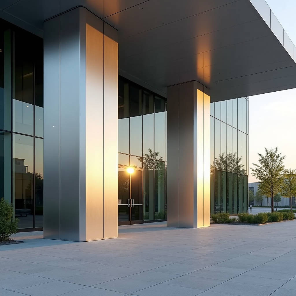
Structural columns define the rhythm of a building facade, yet they rarely receive the engineering attention they demand. When a contractor wraps a steel H-beam or a concrete pier with Aluminum Pillar Cladding, the conversation shifts from simple decoration to a complex interplay of thermal movement, wind load transfer, and sub-frame compatibility. Getting the specification wrong on a 12-meter column run means watching panels buckle under thermal stress six months after handover. This article examines the load-path logic, joint design tolerances, and substrate preparation protocols that separate a cladding system that performs for 20 years from one that fails during its first seasonal cycle.
Why Solid Aluminum Pillar Cladding Outperforms Light-Gauge Alternatives
Not all aluminum cladding products carry the same structural DNA. The market offers two fundamentally different material categories: solid aluminum panels rolled from 5000-series or 3000-series alloy ingots, and thin-gauge composite sheets with polyethylene cores. For pillar applications where flatness, impact resistance, and fire performance matter, the distinction is non-negotiable.
Solid Aluminum Pillar Cladding fabricated from 2.5mm or 3.0mm 5052-H32 alloy delivers a yield strength around 193 MPa. This means a 1-meter-wide panel spanning 600mm between sub-frame members deflects less than 1/200 of its span under a 2.0 kPa wind load, a threshold that satisfies most curtain wall deflection criteria. The material's through-body composition also eliminates the delamination risk that plagues core-based products when exposed to the thermal cycling common on south-facing column faces.
From a fire compliance standpoint, solid aluminum carries a Class A1 rating per EN 13501-1 or an equivalent non-combustible classification under ASTM E136. This matters for projects in jurisdictions enforcing AS 1530.1 or the IBC's non-combustible cladding requirements on high-rise structures. A pillar wrapped in solid 3.0mm aluminum with a ventilated cavity behind it does not contribute fuel load to a facade fire, a consideration that has reshaped specification habits in markets from Melbourne to Dubai since 2017.
Fabrication precision also separates solid panels from lighter alternatives. CNC folding and routing on solid aluminum allow for crisp 90-degree returns with a 1.5mm bend radius, producing panel edges that read sharp and clean against the column corner. The material's inherent stiffness means fewer intermediate stiffeners are required, reducing the parts count and simplifying installation sequencing on-site.
Thermal Movement: The Silent Specification Killer
Aluminum expands at roughly 0.024mm per meter per degree Celsius. On a 10-meter column experiencing a 60°C surface temperature swing between winter night and summer afternoon, the total linear movement approaches 14.4mm. If the cladding system does not accommodate that movement, the panels will either buckle outward or tear at the fastener points.
Three joint strategies dominate well-engineered Aluminum Pillar Cladding installations:
- Open joints with shadow gaps: Panels are separated by 8-12mm gaps backed by a dark-colored EPDM gasket or a recessed drainage profile. The gap absorbs thermal movement invisibly while maintaining the visual continuity of the column face.
- Sliding clip systems: Each panel is fixed at one anchor point and allowed to slide at all others through slotted holes in the aluminum sub-frame. The slot length is calculated based on the expected movement range plus a 3mm safety margin.
- Interlocking tongue-and-groove joints with expansion breaks: Continuous vertical joints incorporate a 15mm expansion break every 4-5 meters, filled with a UV-stable silicone sealant that remains elastic across the expected temperature range.
The sub-frame material choice amplifies or mitigates the problem. An aluminum sub-frame (6063-T5 extruded profiles) expands at nearly the same rate as the cladding panels, creating a matched system where differential movement is negligible. A galvanized steel sub-frame, by contrast, expands at roughly half the rate of aluminum, introducing shear stress at every fastener connection. On projects where steel sub-frames are unavoidable due to fire rating requirements or cost constraints, specifying stainless steel fasteners with nylon isolation washers becomes essential to prevent galvanic corrosion and allow micro-movement at each connection point.
Wind Load Transfer Through Column Cladding Systems
A freestanding column on an open plaza or a portico column at a building entrance experiences wind pressures that differ markedly from those on the main facade plane. The cylindrical or polygonal shape of a column creates a pressure distribution that peaks at the stagnation point facing the wind and drops sharply as the flow separates around the sides. For a square column, the corners experience suction pressures that can exceed the positive pressure on the windward face by a factor of 1.5 to 2.0.
Engineers calculating wind loads for Aluminum Pillar Cladding should reference the pressure coefficient data in ASCE 7-22 Chapter 30 for solid freestanding signs and walls, applying the appropriate shape factors for the column's aspect ratio. A typical design wind pressure for a 15-meter-tall column in Exposure Category B with a basic wind speed of 45 m/s ranges from 1.8 kPa on the windward face to -3.2 kPa at the corners.
The load path runs from the cladding panel face through the aluminum stiffeners (typically 2mm-thick hat sections or folded channels) into the horizontal girts, then into vertical mullions, and finally into the structural column itself via stainless steel brackets. Each connection point in this chain must be verified for both tension and shear capacity. A common failure mode observed in post-storm facade inspections involves the pull-out of self-tapping screws from aluminum sub-frame members where the screw embedment depth was insufficient for the calculated tension load.
For projects in cyclone-prone regions such as the Caribbean, the Philippines, or northern Australia, the cladding attachment system should be tested to a minimum of 1.5 times the design pressure in a cyclic loading protocol that simulates the repeated suction-pressure reversals of a tropical storm. The AAMA 501.1 dynamic water penetration test, while designed for window assemblies, provides a useful reference methodology for verifying the weathertightness of column cladding joints under simulated wind-driven rain conditions.
Substrate Preparation for Different Column Types
The structural column behind the cladding dictates the attachment strategy. Three substrate types cover the vast majority of commercial projects:
Structural Steel Columns (H-Beams and Hollow Sections)
Steel columns offer the most straightforward attachment scenario. Brackets can be welded directly to the steel surface using certified fillet welds, or bolted through pre-drilled holes using stainless steel threaded studs. The critical consideration is the zinc-rich primer integrity at weld points. Every weld location must be ground clean, re-primed with a two-component zinc-rich epoxy, and inspected before the aluminum sub-frame is attached. Skipping this step leads to rust bleeding that stains the aluminum cladding from behind within 12-18 months.
Thermal bridging also deserves attention. A steel column with welded aluminum brackets creates a direct thermal path from the exterior cladding to the interior structure. In cold climates, this can drop the interior surface temperature of the column below the dew point, causing condensation inside the building envelope. A 5mm thermal break pad (polyamide or rigid PVC) between the bracket and the column face eliminates this pathway without compromising the bracket's load capacity.
Reinforced Concrete Columns
Concrete columns require post-installed anchors: either expansion anchors for solid concrete or chemical anchors (epoxy or hybrid resin) for concrete of uncertain quality or where vibration during drilling is a concern. The anchor embedment depth must account for the concrete cover thickness and the presence of rebar, which a cover meter survey should map before drilling begins.
Concrete surface irregularity poses a second challenge. Cast-in-place columns often deviate from the design plane by 10-15mm over a 3-meter height. The sub-frame must incorporate an adjustable bracket system with at least 25mm of adjustment range in the out-of-plane direction to absorb these deviations while maintaining a flat cladding plane. A laser survey of the as-built column surface, recorded at 600mm intervals vertically and at each corner horizontally, provides the data needed to pre-set bracket positions before panels arrive on-site.
Existing Masonry or Clad Columns (Retrofit Projects)
Retrofit applications introduce the complication of an unknown substrate. The existing column may have brick veneer, stone cladding, or stucco over a steel or concrete core. The attachment must penetrate through the finish layer into the structural core, which requires exploratory coring to determine the core material and condition. Anchor pull-out tests on a representative sample of the substrate (minimum 5 tests per column type per ASTM E488) provide the allowable load data needed to size brackets and fastener spacing.
Coating Selection for Long-Term Facade Performance
The coating system on Aluminum Pillar Cladding does more than deliver a color match to the facade. It determines the panel's resistance to UV degradation, salt spray corrosion, and industrial pollutants over a 20-30 year service life. Three coating technologies dominate the specification landscape:
| Property | PVDF Fluorocarbon (70% PVDF) | FEVE Fluoropolymer | Polyester Powder Coating |
|---|---|---|---|
| Film Thickness | 30-40 μm (3-coat) | 35-45 μm (3-coat) | 60-80 μm (single coat) |
| Color Retention (10 years) | ΔE ≤ 5 (AAMA 2605) | ΔE ≤ 3 (AAMA 2605) | ΔE ≤ 8-10 (AAMA 2604) |
| Salt Spray Resistance | 4,000+ hours (ASTM B117) | 6,000+ hours (ASTM B117) | 1,000-2,000 hours (ASTM B117) |
| Pencil Hardness | HB-F | F-H | H-2H |
| Typical Warranty | 20 years (color & integrity) | 25-30 years (color & integrity) | 10-15 years (integrity only) |
| Relative Cost Index | 1.0 (baseline) | 1.2-1.4 | 0.6-0.8 |
For coastal projects within 5km of saltwater, the specification should default to PVDF or FEVE with a minimum 35μm total dry film thickness and a chrome-based pretreatment layer. The AAMA 2605 standard defines the performance requirements for high-performance organic coatings on aluminum, including the 10-year Florida exposure test that remains the gold standard for validating color and gloss retention claims.
For interior column cladding in high-traffic areas such as airport terminals or shopping mall atriums, powder coating with a minimum 60μm thickness offers superior scratch resistance. The harder surface (H-2H pencil hardness) withstands the incidental impacts from luggage carts and cleaning equipment that would mar a softer fluoropolymer finish. However, powder coating's lower UV resistance makes it unsuitable for exterior applications in sun-exposed locations.
Fabrication Tolerances and Panel Sizing Logic
The dimensional accuracy of Aluminum Pillar Cladding panels determines how clean the installed joints read from the ground. Industry practice for solid aluminum panel fabrication follows the tolerance framework established in ISO 2768-m for machined edges and formed profiles:
- Panel length and width: ±1.0mm for panels up to 2,000mm, ±1.5mm for panels 2,000-4,000mm
- Diagonal difference: ≤2.0mm for panels up to 2,000mm, ≤3.0mm for larger panels
- Flatness: deviation from plane ≤0.5% of the panel's diagonal dimension
- Bend angle tolerance: ±0.5° for 90° returns
Panel sizing follows a logic driven by material yield, transport constraints, and installation ergonomics. The standard aluminum sheet blank size is 1,500mm × 3,000mm or 1,500mm × 4,000mm, which means a single column face panel can typically span up to 1,200mm in width (after accounting for the return folds) and 3,000-4,000mm in height. For columns wider than 1,200mm per face, panels must be joined horizontally, introducing a horizontal joint that requires careful detailing to avoid water ingress and visible misalignment.
Weight also constrains panel sizing. A 3.0mm-thick solid aluminum panel weighs approximately 8.1 kg/m². A 1.2m × 3.0m panel weighs 29.2 kg, which two installers can handle safely without mechanical lifting assistance. Pushing beyond 35 kg per panel increases the risk of handling damage and slows installation rates. On projects where larger panels are architecturally required, the installation methodology must include vacuum lifters and a panel-handling plan that the general contractor reviews before the cladding package arrives on-site.
Installation Sequencing and Quality Control Checkpoints
The installation of Aluminum Pillar Cladding follows a sequence that must integrate with the general contractor's overall facade program. The process typically spans four phases:
- Survey and bracket setting (2-3 days per column): Laser survey of the as-built column, marking of bracket positions, drilling and anchor installation, pull-out testing of sample anchors, and bracket alignment using shims or adjustable brackets.
- Sub-frame assembly (1-2 days per column): Vertical mullions and horizontal girts are bolted to the brackets, checked for plumb and plane, and torqued to specification. The completed sub-frame is inspected for overall flatness using a 2-meter straightedge.
- Panel installation (2-4 days per column): Panels are lifted into position, engaged with the sub-frame clips, and adjusted for joint alignment. Installation proceeds from bottom to top to allow each panel to rest on the one below during positioning.
- Joint sealing and final inspection (1 day per column): Backing gaskets are inspected, drainage paths are verified, and any face-applied sealant is tooled to a consistent profile. A final visual inspection from multiple viewing angles identifies any waviness or joint irregularity.
For complex projects, the cladding supplier should provide a detailed installation manual with torque values for every fastener type, a joint movement calculation table, and a quality control checklist aligned with the project's inspection and test plan. Suppliers with dedicated technical support teams, such as Futeng®, can provide on-site training for the installation crew during the first column to ensure the methodology is correctly understood before the crew proceeds independently.
Cost Drivers and Budgeting Realities
The installed cost of Aluminum Pillar Cladding varies significantly based on four primary drivers: material thickness, coating specification, column geometry complexity, and site logistics. A breakdown of the cost components reveals where specification decisions have the greatest budget impact:
- Material (35-45% of total): The raw aluminum sheet cost, including the alloy surcharge for 5052 or 5754 marine-grade material. Thicker material (3.0mm vs 2.0mm) adds roughly 30% to the material line item.
- Fabrication (25-30% of total): CNC cutting, folding, routing, stiffener attachment, and any perforation or custom pattern work. Circular column panels require roll-forming, which adds 15-20% compared to flat panels for square columns.
- Coating (15-20% of total): PVDF coating with a 3-coat system costs roughly 2.5 times more than a standard polyester powder coat. Custom metallic or mica finishes add a further 10-15% premium.
- Installation (15-25% of total): Labor, access equipment, and site overhead. Columns above 6 meters height require scaffolding or boom lifts, which can double the installation cost per square meter compared to ground-accessible columns.
For budget estimation purposes, a square column clad in 2.5mm solid aluminum with PVDF coating on a standard aluminum sub-frame system typically falls in the range of $280-420 per square meter of cladding surface, installed, depending on the project location and column height. Circular columns add 15-25% to this baseline. These figures assume a project of at least 200 square meters of total cladding area; smaller packages will carry a higher per-unit cost due to mobilization and fabrication setup charges.
Specifying Aluminum Pillar Cladding for International Projects
When the project team spans multiple countries, the specification must bridge different regulatory frameworks and testing standards. A column cladding system designed to Chinese GB/T standards requires validation against ASTM or EN equivalents before a US or European consultant will approve it. The key bridging documents include:
- Coating performance: GB/T 5237.4 for PVDF coatings maps to AAMA 2605, with the critical equivalence being the 10-year Florida exposure test data.
- Material composition: GB/T 3880 for aluminum alloy chemical composition aligns with ASTM B209 for 5052 alloy, though the allowable impurity ranges differ slightly and should be checked.
- Fire performance: GB 8624 Class A maps to EN 13501-1 Class A1 for non-combustible materials, but the test methodologies differ. Providing test data from both standards eliminates consultant objections.
The ISO 12944 series on corrosion protection of steel structures, while not directly applicable to aluminum, provides a useful framework for defining the corrosivity category of the project site. For C4 (high) and C5 (very high) corrosivity environments, the specification should require stainless steel fasteners (316 grade minimum), PVDF or FEVE coating, and a ventilated cavity behind the cladding to prevent moisture entrapment.
Shipping and logistics also factor into the specification. Solid aluminum panels are heavy and occupy significant container volume. A 40-foot high-cube container can hold approximately 600-800 square meters of fabricated panels, depending on panel dimensions and packaging density. For projects in regions with limited port infrastructure, the packaging specification must include marine-grade plywood crating with desiccant packs and vapor barrier wrapping to prevent condensation damage during extended transit or storage.
Common Failure Modes and How to Prevent Them
Engineering a cladding system means understanding how it fails. The most frequent failure modes observed in Aluminum Pillar Cladding installations, and their prevention strategies, include:
Oil canning (visible waviness): Caused by residual stresses in the aluminum sheet that release during fabrication or thermal cycling. Prevention starts with specifying stretcher-leveled sheet with a flatness tolerance of I-1 per The Aluminum Association flatness standards. Adding stiffeners at 400-500mm centers rather than 600mm also reduces the unsupported panel area that can exhibit waviness.
Fastener corrosion: Occurs when carbon steel screws are used in contact with aluminum in the presence of moisture. The galvanic series places aluminum and carbon steel far apart, creating a battery effect that corrodes the aluminum around the fastener hole. Prevention requires 316 stainless steel fasteners with EPDM washers at every connection point, with no exceptions for "temporary" or "interior" applications.
Joint sealant failure: Silicone sealant loses adhesion to PVDF-coated aluminum over time if the coating surface is not properly prepared. The solution is a two-step process: lightly abrade the coating surface at the sealant contact area with a fine Scotch-Brite pad, then wipe with isopropyl alcohol immediately before sealant application. The sealant manufacturer's adhesion test (ASTM C794 peel adhesion) on the actual coated panel samples confirms compatibility before site work begins.
Water entrapment behind panels: A cladding system that is sealed too tightly at the bottom traps water that enters through imperfect top joints or condensation. Every column cladding installation should include 6mm-diameter weep holes at the bottom closure flashing, spaced at 300mm centers, to allow drainage. The cavity behind the panels should be ventilated at both top and bottom to promote airflow that dries any residual moisture.
Making the Right Specification Decision
Aluminum Pillar Cladding sits at the intersection of structural engineering, material science, and architectural expression. The specification decisions made during the design phase, particularly around material thickness, joint design, coating selection, and attachment methodology, determine whether the installed system performs quietly for decades or generates callbacks within the first year.
For project teams navigating these decisions, the most reliable approach is to work backward from the performance requirements: define the design wind pressure, the corrosivity category, the fire rating requirement, and the desired aesthetic outcome. Let those parameters drive the material and system choices rather than starting from a cost target and working forward. The cost difference between a properly engineered system and a marginal one, measured as a percentage of the total facade package, is small. The cost of remediating a failed cladding installation on a completed building is not.
Specifying solid aluminum panels with a proven PVDF or FEVE coating, an aluminum sub-frame matched for thermal compatibility, and a joint design that accommodates the calculated movement range produces a column cladding system that meets the ASTM and AAMA performance benchmarks that international consultants require. The engineering is straightforward, the material behavior is well understood, and the failure modes are preventable. What remains is the discipline to apply that knowledge consistently across every column on every project.