Aluminum Parapet Panel Engineering for Wind Load and Long Term Weather Resistance
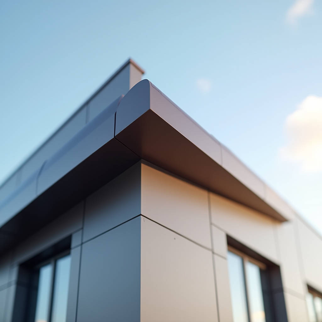
When a building envelope fails at the roof edge, the consequences cascade fast. Water intrusion, corroded fasteners, wind-lifted flashing, and structural degradation all trace back to one often-overlooked intersection: where the vertical wall meets the horizontal roof. An Aluminum Parapet Panel addresses this junction directly. It is not a coping, not a cap, and not a composite sandwich. It is a solid, single-skin aluminum sheet fabricated to wrap the parapet wall and integrate with both the cladding below and the roofing membrane above. Architects and contractors who specify solid aluminum at this transition point are solving for three things simultaneously: wind-driven rain resistance, thermal movement accommodation, and long-term corrosion immunity. The material choice here matters more than most realize. A 2.5mm or 3.0mm solid 3003-H14 or 5052-H32 aluminum panel, finished with a 70% PVDF coating, can outlast the roofing membrane it protects. This article examines the engineering logic, the fabrication tolerances, the attachment methods, and the cost drivers that determine whether a parapet cladding detail performs for 10 years or 40.
What Separates a Solid Aluminum Parapet Panel from a Coping
Terminology confusion costs projects money. A coping is a narrow cap that sits atop the parapet wall, typically bent from 0.040-inch or 0.050-inch aluminum coil stock, and its primary job is to shed water off the top surface. An Aluminum Parapet Panel is a different product entirely. It is a full-height cladding element that covers the vertical face of the parapet, often wrapping from the roof-side face, across the top, and down the exterior face in one continuous formed piece. The distinction matters because the structural demands are different. A coping deals with gravity and cap fastening. A parapet panel deals with wind suction, thermal expansion across a much larger surface area, and the need to align precisely with the vertical wall cladding system below.
Solid aluminum panels in this application are fabricated from coil or sheet stock in thicknesses ranging from 2.0mm to 3.0mm. The alloy selection follows standard architectural cladding practice: 3003-H14 for general applications, 5052-H32 where higher tensile strength is needed for wind-load spans. These are not composite panels with polyethylene cores. They are homogeneous aluminum throughout, which means they do not delaminate, do not wick moisture at cut edges, and do not require edge sealing as part of the fabrication process. For the parapet condition specifically, this homogeneity becomes critical because the top bend is exposed to standing water, ice, and UV radiation from multiple angles simultaneously.
Wind Load at the Parapet: The Engineering Reality
Wind tunnel studies consistently show that the highest suction pressures on a building envelope occur at corners, eaves, and parapet edges. The ASCE 7 standard defines these as Zone 5 pressures, and they can be 2.5 to 3.5 times higher than the pressure at the mid-span of a wall. A parapet panel that feels solid on a calm day is subjected to cyclical negative pressure during every wind event. The panel must resist not just the magnitude of the load but the fatigue effect of repeated loading cycles over decades.
For a solid aluminum parapet panel spanning between girts or sub-framing at 600mm centers, the allowable wind load can be calculated using the bending stress formula for a simply supported plate. A 3.0mm thick 5052-H32 panel with a yield strength of 193 MPa, spanning 600mm, can resist a uniform pressure of approximately 2.8 kPa at a deflection limit of L/60. For projects in hurricane-prone regions or buildings exceeding 60 meters in height, the sub-framing spacing must tighten to 400mm or the panel thickness must increase to 4.0mm. The attachment method also changes: exposed fasteners through the panel face become unacceptable at high wind loads because the stress concentration around the fastener hole can initiate tear-out. Instead, a concealed clip system with continuous aluminum extrusions engages the panel return leg, distributing the load along the entire edge.
Attachment Methods and Thermal Movement
Aluminum expands at roughly 2.4mm per linear meter across a 100°C temperature swing. A 3-meter-long parapet panel can grow or shrink by over 7mm between a winter night and a summer afternoon. If the attachment system does not accommodate this movement, the panel will buckle, the fasteners will loosen, or the sealant joints will tear. Three attachment strategies dominate the market:
- Fixed-point and sliding-point system: One fastener location is locked as the fixed point; all other attachment points use slotted holes that allow the panel to slide. This is the most common approach for panels up to 4 meters in length.
- Continuous clip with expansion joints: Extruded aluminum clips engage the panel top and bottom returns. Expansion joints are introduced every 3 to 4 meters, with a 10mm to 12mm gap filled with low-modulus silicone sealant.
- Cassette system with rear tray: A rear tray is fixed to the substrate, and the front panel hooks onto it. The front panel floats independently, absorbing movement without transferring stress to the fasteners.
Each method has a cost implication. The fixed-point/sliding-point system is the most economical for low-rise commercial buildings. The cassette system, while more expensive in material and fabrication, eliminates visible fasteners and provides the cleanest aesthetic for high-end architectural work. For projects where the parapet is highly visible from street level, the cassette approach often justifies its premium.
Coating Performance at the Roof Edge
The parapet is the most aggressively exposed location on any building facade. It receives direct UV radiation on the top surface, reflected UV from the roofing membrane, standing water after rain, and in cold climates, repeated freeze-thaw cycles. The coating system on an Aluminum Parapet Panel must be specified with this microclimate in mind.
PVDF (polyvinylidene fluoride) coatings, commonly referred to by the trade name Kynar 500® or Hylar 5000®, are the industry benchmark for architectural aluminum. The resin content must be a minimum of 70% PVDF to meet AAMA 2605, the highest performance standard for architectural coatings. The total dry film thickness should be 30-35 microns for a two-coat system and 40-45 microns for a three-coat system that includes a clear topcoat. The primer layer, typically 5-8 microns, is critical for adhesion and corrosion resistance. A chrome-based pretreatment under the primer provides the galvanic barrier that prevents filiform corrosion at cut edges and fastener holes.
The table below compares coating options for parapet applications based on real-world performance data:
| Coating System | Standard | Film Thickness | UV Resistance (Years to 50% Gloss Retention) | Relative Cost | Best Application |
|---|---|---|---|---|---|
| PVDF 70% (3-Coat) | AAMA 2605 | 40-45 µm | 30+ | 1.0x (baseline) | High-rise, coastal, premium architectural |
| PVDF 70% (2-Coat) | AAMA 2605 | 30-35 µm | 25-30 | 0.85x | Standard commercial, inland |
| FEVE (Fluoroethylene Vinyl Ether) | AAMA 2605 | 35-40 µm | 25-30 | 1.05x | High-gloss requirements, field-repairable |
| Polyester (Super Durable) | AAMA 2604 | 25-30 µm | 10-15 | 0.65x | Low-rise, budget-sensitive, interior parapet faces |
| Anodized (Class I) | AA-M10C22A31 | 18-25 µm | 20-25 (color-dependent) | 1.15x | Monumental, uniform color expectations |
For parapet applications, the three-coat PVDF system is the safest specification. The incremental cost over a two-coat system is roughly 15%, but the clear topcoat adds measurable protection against chalking on the top horizontal surface where water can pond. On projects where the parapet panel color is a dark shade (charcoal, black, dark bronze), the three-coat system becomes functionally necessary because dark colors absorb more solar radiation, accelerating resin degradation in a two-coat system.
Fabrication Tolerances and the Problem of the Top Bend
The most technically demanding part of a parapet panel is the top bend. The panel must transition from the exterior vertical face, across the top of the parapet wall, and down the interior face. This requires at least two bends, and often a third if a drip edge is incorporated on the interior side. Each bend introduces springback, and the cumulative effect across multiple bends can throw the panel out of dimensional tolerance by 2mm to 4mm if not accounted for in the flat pattern.
Solid aluminum panels are fabricated on CNC press brakes with tooling selected for the specific alloy and thickness. The bend radius for 3.0mm 5052-H32 should be a minimum of 2.5 times the material thickness (7.5mm inside radius) to avoid stress cracking at the bend line. Tighter radii are achievable with 3003 alloy, which has better formability but lower strength. The flat pattern calculation must account for the bend deduction, which varies with the die opening, punch radius, and material properties. A well-calibrated fabricator will hold a tolerance of ±1.0mm on the overall panel dimensions and ±0.5mm on the bend-to-bend distance.
The top surface of the parapet panel should slope inward toward the roof, with a minimum pitch of 1:12. This prevents water from running down the exterior face, which would cause streaking and staining over time. The slope is achieved either by the structural parapet wall itself being sloped, or by the panel fabrication incorporating a tapered top section. The latter is more expensive but provides a guaranteed slope regardless of substrate irregularities.
Integration with Roofing and Wall Cladding
A parapet panel does not exist in isolation. It interfaces with the roofing membrane on the interior side and the wall cladding on the exterior side. Both interfaces are potential leak points if not detailed correctly. The interior leg of the parapet panel must extend below the top of the roofing membrane by at least 150mm. The roofing membrane is then carried up the interior face of the parapet wall and terminated under a counterflashing that is part of the parapet panel system or a separate reglet cast into the wall.
On the exterior side, the parapet panel must align with the wall cladding system below. If the wall cladding is also solid aluminum panels, the joint can be a simple horizontal expansion joint with a 10mm gap and backer rod. If the wall cladding is a different material (brick, precast concrete, curtain wall), the transition requires a sub-sill or flashing that directs water outward and away from the wall below. The parapet panel should overlap this flashing by a minimum of 50mm, creating a shingle effect that prevents wind-driven rain from penetrating behind the panel.
For projects where the wall cladding is a rainscreen system, the parapet panel must be detailed to allow ventilation air to exit at the top of the cavity. This is achieved by leaving a continuous slot or a series of punched openings at the top of the exterior wall panel, behind the parapet panel's exterior leg. The opening area should equal the ventilation inlet area at the bottom of the rainscreen cavity to maintain convective airflow. Blocking this airflow traps moisture and accelerates corrosion of the sub-framing.
Cost Drivers and Budgeting
The installed cost of a solid aluminum parapet panel system varies significantly based on four primary factors: panel thickness, coating specification, attachment method, and project geography. The following estimates are based on mid-2024 material and labor rates for commercial projects in North America, with panels fabricated to standard architectural tolerances:
- 2.0mm 3003-H14, 2-coat PVDF, exposed fastener system: $45–$55 per square foot installed. Suitable for low-rise retail and industrial buildings where the parapet is not a prominent architectural feature.
- 2.5mm 5052-H32, 3-coat PVDF, concealed clip system: $65–$80 per square foot installed. This is the specification sweet spot for mid-rise commercial and institutional projects.
- 3.0mm 5052-H32, 3-coat PVDF, cassette system with custom color: $90–$120 per square foot installed. Reserved for high-end architectural work where the parapet is a visible design element.
Fabrication complexity adds cost non-linearly. A simple L-shaped panel with two bends is straightforward. A panel with a drip edge, multiple return legs, and CNC-punched ventilation slots can double the fabrication time. Custom colors outside the standard PVDF palette add 8-12 weeks to lead time and a 15-25% premium to the material cost. For projects with tight schedules, specifying a standard color from the manufacturer's in-stock range can save both time and money. Suppliers like Futeng® maintain inventory of popular PVDF colors that can reduce lead times for solid aluminum parapet panels to 4-6 weeks for standard profiles.
Corrosion Considerations in Coastal and Industrial Environments
Aluminum resists corrosion through the formation of a stable oxide layer. In most environments, this passive layer is self-maintaining. However, in coastal environments with airborne chlorides, and in industrial environments with sulfur dioxide, the oxide layer can break down, leading to pitting corrosion. The parapet is particularly vulnerable because it is exposed to rain washing, which concentrates contaminants at the top edge.
For projects within 5 kilometers of a coastline, the alloy selection should shift from 3003 to 5052, which has better resistance to chloride-induced pitting. The coating specification should include a marine-grade pretreatment with a minimum chrome coating weight of 650 mg/m². The AAMA 2605 standard includes salt spray testing (ASTM B117) as part of the qualification process, but specifying a minimum of 4,000 hours without blistering provides an additional margin of safety for coastal applications.
For industrial environments with high sulfur content, the coating must resist acid rain etching. PVDF coatings are inherently resistant to acid attack, but the pigment selection matters. Inorganic pigments (mixed metal oxides) are more stable than organic pigments in acidic conditions. A dark bronze panel colored with inorganic pigments will outlast an identically colored panel using organic pigment systems by 10-15 years in an industrial atmosphere.
Quality Control and Site Verification
The difference between a parapet panel that performs and one that fails often comes down to what happens on site. Panels that leave the factory within specification can be compromised by improper handling, incorrect fastener installation, or substrate irregularities that were not identified before installation began.
Before panels are installed, the substrate must be surveyed for flatness. A deviation of more than 3mm over a 2-meter straightedge will telegraph through the panel, creating visible waves on the finished surface. The sub-framing must be installed to the same tolerance. Fasteners must be stainless steel (Type 304 or 316 for coastal), and they must be installed to the manufacturer's specified torque. Over-torquing a fastener in a slotted hole defeats the purpose of the slot by locking the panel in place and preventing thermal movement.
On the fabrication side, the incoming aluminum coil or sheet should be traceable to the mill, with certificates of compliance showing the alloy, temper, and mechanical properties. The ASTM B209 standard governs aluminum sheet and plate for architectural applications. Coating thickness should be verified with an eddy-current gauge on every panel, with measurements taken at the center of flat areas and at the bend lines, where coating thinning can occur during the forming process. A reputable fabricator will provide a coating thickness report as part of the project documentation.
Thermal Performance and Building Code Compliance
Building energy codes increasingly treat the parapet as part of the thermal envelope. The parapet is a thermal bridge. Heat conducts through the aluminum panel, through the steel or aluminum sub-framing, and into the building interior. In cold climates, this creates a cold stripe on the interior ceiling at the perimeter, which can lead to condensation and mold growth.
To address this, the parapet panel system should include a thermal break between the panel and the substrate. This can be a continuous strip of high-density polyisocyanurate insulation, 12mm to 25mm thick, placed between the sub-framing and the concrete or steel parapet wall. The panel itself is not the primary insulation layer, but the thermal break prevents the metal components from creating a direct conductive path. The ASHRAE 90.1 standard provides guidance on continuous insulation requirements for parapets in different climate zones.
For projects pursuing LEED or other green building certifications, the aluminum content of the panels can contribute to recycled content credits. Most architectural aluminum sheet contains 50-70% recycled content, the majority of which is post-industrial scrap from the rolling and fabrication processes. Specifying aluminum from suppliers who provide Environmental Product Declarations (EPDs) supports the documentation requirements for these credits.
Common Failure Modes and How to Prevent Them
Understanding how parapet panels fail is more instructive than studying how they succeed. The most common failure modes observed in the field include:
- Sealant joint failure: Sealant is the weakest link in any parapet system. UV exposure, movement cycling, and poor surface preparation during installation cause sealant to lose adhesion within 5-10 years. The solution is to design joints that do not rely on sealant as the primary water barrier. A two-stage joint with a vented outer seal and a drained inner seal provides redundancy.
- Fastener corrosion: Carbon steel fasteners used in contact with aluminum create a galvanic couple. The aluminum acts as the anode and corrodes sacrificially around the fastener hole. Stainless steel fasteners eliminate this problem, but the stainless steel must be isolated from the aluminum with a nylon washer to prevent the less common but still possible galvanic reaction between stainless and aluminum in the presence of an electrolyte.
- Oil canning: Flat aluminum panels can exhibit waviness known as oil canning, which is a visual distortion caused by residual stresses in the material. It is not a structural failure, but it is unacceptable on high-visibility parapets. Specifying a minimum of 2.5mm thickness, using a stiffer alloy (5052), and incorporating a slight break shape or stiffening ribs in the panel design all reduce the risk of oil canning.
- Substrate rot: If the parapet wall is wood-framed and water penetrates behind the panel, the wood can rot without visible signs on the exterior. The panel remains intact while the substrate loses structural capacity. A waterproof membrane behind the panel, with drainage at the bottom, separates the wet zone from the structural substrate.
Specifying for Longevity: A Practical Checklist
When writing a specification for an Aluminum Parapet Panel system, the following points should be addressed explicitly in the project documentation. Leaving any of these to the installer's discretion introduces risk that may not manifest for years:
- Alloy and temper: Specify 5052-H32 for high-wind or coastal locations, 3003-H14 for standard inland applications.
- Panel thickness: Minimum 2.0mm for low-rise, 2.5mm for mid-rise, 3.0mm for high-rise or exposed sites.
- Coating: 70% PVDF, AAMA 2605 compliant, three-coat system for dark colors and coastal environments.
- Attachment: Concealed clip or cassette system with thermal movement accommodation. Exposed fasteners only for low-rise, non-architectural applications.
- Fasteners: Type 316 stainless steel, isolated from aluminum with nylon washers.
- Substrate: Flatness within 3mm per 2 meters. Thermal break required in climate zones 4 and above.
- Sealant: Low-modulus, neutral-cure silicone. Two-stage joint design where possible.
- Testing: Mock-up required. Wind load test per ASTM E330 for projects over 30 meters in height.
The building envelope is only as strong as its weakest detail. The parapet, perched at the top of the wall and exposed to wind, water, and sun from every direction, is a detail that rewards careful specification. A solid aluminum panel, properly engineered and installed, turns a vulnerable transition into a durable asset. The investment in the right alloy, the right coating, and the right attachment system pays back over decades of maintenance-free performance. For contractors and specifiers who have dealt with the consequences of a failed parapet, the value of getting this detail right is not theoretical. It is measured in avoided callbacks, avoided water damage claims, and the quiet confidence that comes from knowing the building can weather whatever comes at it.