Aluminum Coping Panel Engineering Guide Alloy Selection Wind Uplift and Splice Joint Design
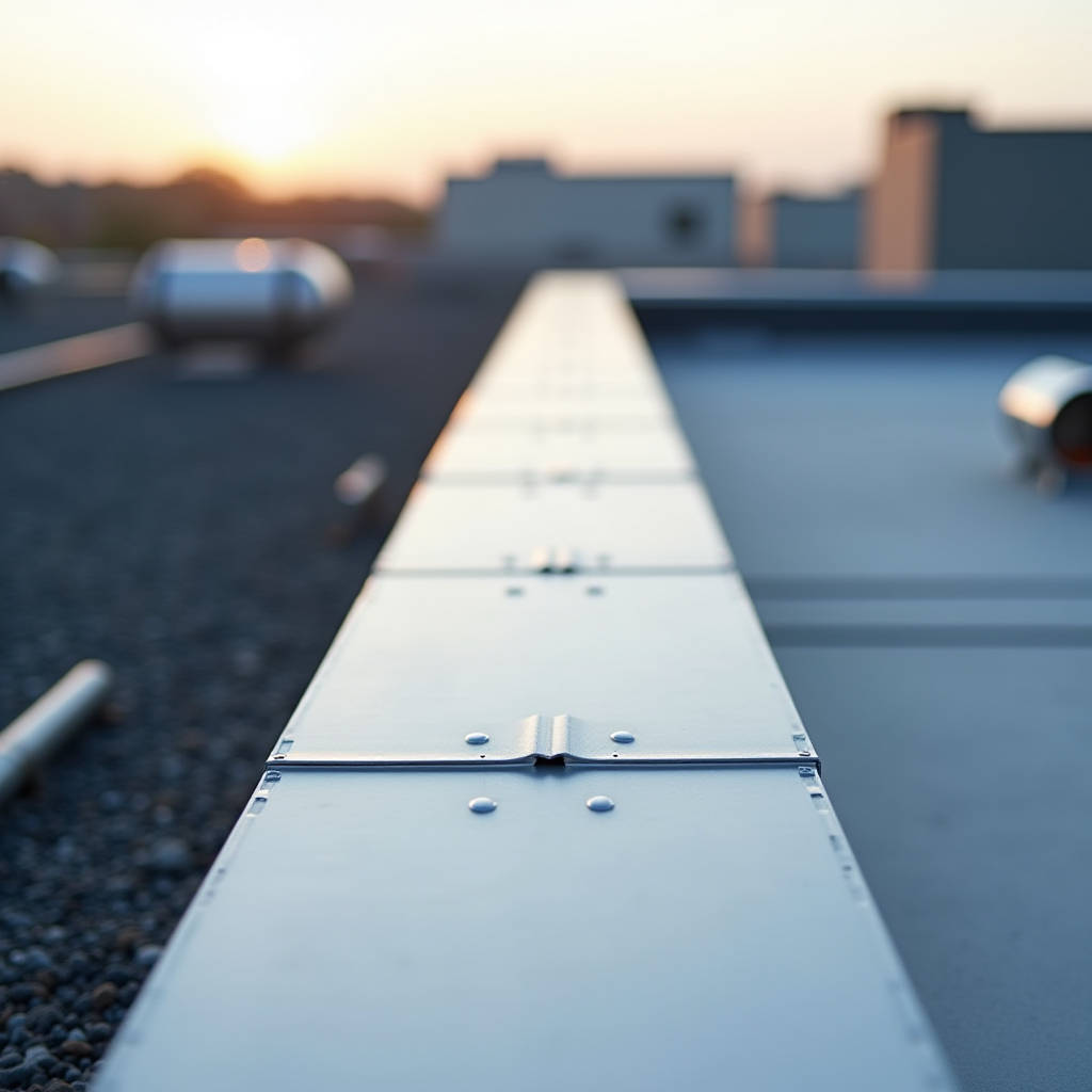
Wind-driven rain peeling back a failed coping system can turn a $200,000 roofing warranty into worthless paper within one storm season. The parapet cap sits at the most vulnerable intersection of the building envelope—roof membrane, wall cladding, and structural substrate all converge at this narrow horizontal plane. When an Aluminum Coping Panel is specified correctly, it manages this junction with mechanical precision. When it is not, water infiltration migrates downward through the wall assembly, triggering corrosion in steel studs, delamination of interior finishes, and mold propagation inside cavity insulation. This article examines the structural and material-specific factors that separate a coping detail that survives a 50-year weather cycle from one that generates a call to the contractor's attorney within 18 months of substantial completion.
What Actually Fails First: The Anatomy of Coping Degradation
Most post-mortem analyses of coping failures do not point to the aluminum material itself. The 3003-H14 and 5052-H32 alloys commonly used in solid aluminum coping carry yield strengths between 145 and 195 MPa, more than adequate for the dead loads involved. The failure chain almost always starts at the joint. Thermal expansion and contraction—aluminum moves at approximately 2.38 mm per linear meter across a 100°C temperature swing—applies cyclical stress to splice plates, sealant beads, and concealed fasteners. Over 10 to 15 years, the sealant loses adhesion to the PVDF-coated surface, the splice plate shifts, and water finds a path.
What makes this particularly insidious is that the leak rarely presents directly below the coping. Water travels laterally along the top track of the parapet framing, sometimes emerging 6 meters from the actual entry point. Forensic investigation of a 2018 mid-rise residential project in Manchester traced persistent fifth-floor ceiling staining to a 3mm gap in a coping splice joint on the opposite end of the building. The contractor had spent £47,000 re-sealing windows that were never the problem.
The Splice Joint: Where Specifications Get Vague
Standard architectural specifications often include a single line about coping joints: "Provide splice plates with sealant." That brevity is expensive. A proper Aluminum Coping Panel splice detail must address four distinct performance requirements simultaneously: water penetration resistance, thermal movement accommodation, electrical continuity for lightning protection, and wind uplift resistance per ANSI/SPRI ES-1.
The most reliable approach in high-wind zones uses a 1.5mm thick internal aluminum splice plate with a nominal 50mm overlap on each side, bedded in a non-skinning butyl sealant that remains pliable at -40°C. The splice plate is mechanically fastened to one side only—the other side floats. This allows the coping to move without shearing the sealant. A 2021 study by the Metal Construction Association documented that floating-splice coping assemblies maintained water penetration resistance after 2,000 thermal cycles, while rigid-splice assemblies began leaking at an average of 840 cycles.
Material Selection: Why Alloy and Temper Matter More Than Thickness
Procurement managers sometimes default to specifying coping by gauge alone—0.050 inch (1.27mm) or 0.063 inch (1.60mm)—without addressing the metallurgy behind the number. This is a mistake. The difference between 3003-H14 and 5052-H32 in a coping application is not marginal; it determines whether the panel will oil-can under solar gain or remain flat across a 600mm-wide parapet.
| Property | 3003-H14 | 5052-H32 | Relevance to Coping |
|---|---|---|---|
| Tensile Yield Strength | 145 MPa | 195 MPa | Resistance to denting from dropped tools, hail, maintenance foot traffic |
| Elongation at Break | 8-16% | 12-18% | Formability at brake lines; tighter bend radii without cracking |
| Thermal Conductivity | 162 W/m·K | 138 W/m·K | Lower conductivity reduces thermal bridging through parapet |
| Corrosion Resistance (Salt Spray, ASTM B117) | Good | Excellent | Coastal and industrial atmosphere performance |
| Relative Cost Index | 1.0 (baseline) | 1.15-1.25 | Budget impact on linear meter pricing |
For inland projects with standard parapet widths up to 450mm, 3003-H14 at 2.0mm thickness performs adequately when fabricated with proper stiffening ribs. For coastal installations, any parapet exceeding 500mm in width, or projects where the coping will be subjected to maintenance personnel walking on it, 5052-H32 at 2.5mm minimum is the defensible specification. The additional 15-25% material cost is recovered through avoided callbacks. Futeng® has supplied 5052-H32 solid aluminum coping panels for several high-rise coastal projects in Southeast Asia, where salt-laden monsoon winds create a corrosion environment comparable to ASTM B117 continuous spray conditions.
Wind Uplift: ANSI/SPRI ES-1 Is a Floor, Not a Ceiling
The ANSI/SPRI ES-1 standard, "Wind Design Standard for Edge Systems Used with Low Slope Roofing Systems," provides a calculation methodology that many specifiers treat as a compliance checkbox. The standard requires edge systems to resist design wind loads based on ASCE 7, with a minimum safety factor of 2.0 for metal edge systems. However, the standard's test method—applying uplift pressure to a 2.4-meter-long specimen—does not capture the behavior of coping at building corners, where wind pressures can be 2.5 to 3 times higher than the field-of-wall pressure.
Practically, this means a coping system that passes ES-1 testing at the calculated design pressure for the building's field zone may still be inadequate for corner zones. The FM Global Loss Prevention Data Sheet 1-49 provides more conservative guidance, recommending that perimeter edge flashing (including coping) be designed for the corner-zone pressure across the entire building perimeter. This adds cost but eliminates the weakest-link problem inherent in zone-based design.
Fastener Spacing and the Pull-Through Problem
A concealed-fastener Aluminum Coping Panel system transfers wind uplift loads through the cleat or continuous anchor bar into the substrate. The failure mode is rarely the fastener pulling out of the substrate—it is the fastener head pulling through the aluminum cleat. For 2.0mm 3003-H14 aluminum, a #12 self-drilling screw with an 8mm head diameter can pull through at approximately 1.2 kN under static load. Under cyclic wind loading, the fatigue threshold drops to roughly 0.7 kN.
For a parapet in a 50 m/s (112 mph) design wind speed zone, corner-zone net uplift pressures can reach 4.8 kPa. On a 600mm-wide coping with fasteners at 600mm centers, each fastener must resist approximately 1.7 kN. This exceeds the fatigue threshold for 2.0mm material. The solution is either reducing fastener spacing to 400mm centers or increasing cleat material thickness to 2.5mm minimum. The second option is generally more cost-effective, as the additional aluminum cost is offset by reduced labor for fastener installation.
Coating Systems: PVDF, FEVE, and the 20-Year Color Shift
Architectural coping is the most visually exposed horizontal surface on a building. Viewed from the street, the coping line defines the building's silhouette against the sky. Viewed from a rooftop terrace, the coping is the foreground element. Color fade, chalk, and gloss degradation on coping are more noticeable than on vertical wall panels because the horizontal surface receives direct solar radiation at a higher angle of incidence throughout the day.
Standard PVDF (polyvinylidene fluoride) coatings using 70% Kynar 500® or Hylar 5000® resin systems, applied at a minimum 25μm dry film thickness in a three-coat system, deliver approximately 20-25 years to a Delta E of 5 in temperate climates. In high-UV environments—Dubai, Perth, Phoenix—that timeline compresses to 15-18 years. FEVE (fluoroethylene vinyl ether) coatings, which are thermosetting rather than thermoplastic, offer a 30+ year service life with superior gloss retention. The trade-off is cost: FEVE typically adds 25-35% to the coating cost per square meter compared to standard PVDF.
For projects where the coping color matches the facade, this differential aging creates a problem. The vertical PVDF-coated wall panels, receiving less direct radiation, fade more slowly than the horizontal coping. After 15 years, the coping and the wall panels are visibly different colors. The specification strategy to mitigate this is either: specify FEVE for the coping while using PVDF for the wall panels (the faster-aging coating goes on the less-exposed surface), or specify the same PVDF system for both but plan for recoating or replacement of the coping at year 20. The American Architectural Manufacturers Association (AAMA) publishes AAMA 2605, the most stringent performance specification for architectural coatings, which should be referenced in all coping coating specifications.
Fabrication Tolerances: The 3mm Rule That Prevents 30mm Gaps
Solid aluminum coping is brake-formed from flat sheet. The dimensional accuracy of the finished panel depends on the precision of the brake press, the skill of the operator, and—critically—the allowance made for springback. Aluminum alloys exhibit springback of 2-5 degrees depending on the alloy temper, bend radius, and material thickness. A coping profile with four bends can accumulate a 15mm dimensional error across its width if springback is not compensated in the tooling setup.
Field tolerances compound this. Concrete parapet walls are rarely within the ±10mm flatness that a coping fabricator might assume. A 2019 survey of 120 commercial building parapets in the UK found that 68% exceeded ±15mm in flatness along any 3-meter length. The coping system must accommodate this variability without forcing the installer to field-modify panels—field cuts destroy the factory-applied coating edge protection and create initiation points for filiform corrosion.
The practical solution is a two-part approach: specify a continuous aluminum anchor bar that is shimmed to level during installation, independent of the parapet substrate, and specify coping panels with a 20mm minimum internal clearance between the panel underside and the top of the parapet. This provides a zone for the anchor bar adjustment without the panel bottoming out on the substrate. The ASTM International standard B209/B209M governs aluminum sheet and plate tolerances and should be referenced for raw material flatness.
Thermal Performance: The Parapet as a Thermal Bridge
Building codes increasingly target thermal bridging at parapets. ASHRAE 90.1-2019 and the International Energy Conservation Code (IECC) require continuous insulation at parapets in most climate zones. A solid aluminum coping panel, with a thermal conductivity of 138-162 W/m·K, creates a direct thermal bridge from the exterior to the parapet substrate unless thermally broken.
The thermal break in a coping system is typically a 6-10mm continuous layer of rigid insulation or a proprietary thermal isolator pad between the aluminum anchor bar and the parapet substrate. Without this break, the linear thermal transmittance (Psi-value) of a typical parapet detail can reach 0.8-1.2 W/m·K. With a properly designed thermal break, this drops to 0.15-0.30 W/m·K. On a 200-meter building perimeter in Climate Zone 5, the annual energy penalty of an unbroken parapet coping detail can exceed 15,000 kWh—roughly $2,000-3,000 per year at commercial electricity rates, compounding over the building's life.
Condensation risk is the companion problem. When warm, moist interior air contacts the cold underside of an unbroken aluminum coping in winter, condensation forms. This moisture drips onto the top of the parapet wall and can saturate the insulation, reducing its thermal performance and promoting mold growth. The National Fenestration Rating Council (NFRC) does not rate coping, but the principles of thermal break design from window and curtain wall systems apply directly to parapet coping details.
Installation Sequencing: Why Coping Should Go On Last—And Usually Does Not
The logical construction sequence places coping installation after the roof membrane is fully installed, flashed, and tested. In practice, roofing contractors often install temporary coping or leave the parapet exposed while waiting for the metal panel subcontractor to mobilize. This gap—sometimes weeks, sometimes months—exposes the parapet to weather. Water entering the parapet cavity during this window can saturate gypsum sheathing, initiate corrosion in steel studs, and create conditions that the permanent coping is then expected to seal in.
A well-managed Aluminum Coping Panel installation sequence includes a mandatory flood test of the roof membrane before coping installation begins, a requirement that the coping contractor is on site within 48 hours of the roofing contractor completing parapet flashing, and a prohibition on temporary coping systems that penetrate the roof membrane with mechanical fasteners. The last point is frequently violated; temporary coping fastened through the membrane creates a leak path that the permanent coping cannot address.
"The single most common error we document in parapet failure investigations is the sequence problem—coping installed too late, temporary measures damaging the substrate, and no one accountable for the gap between roofing and coping trades." — Adapted from industry forensic engineering reports.
Supply Chain Considerations: Lead Times and Global Sourcing
Solid aluminum coping panels are not an off-the-shelf product for most projects. The brake-forming, welding of end caps and miters, and application of PVDF or FEVE coatings are project-specific processes. Typical lead times from approved shop drawings to delivery range from 8 to 14 weeks, depending on the complexity of the profile, the coating system, and the fabricator's backlog.
For international projects, the logistics of shipping 3-meter-long brake-formed coping panels add cost and risk. Panels are typically crated in wooden frames with foam separation layers to prevent coating abrasion during transit. Ocean freight from Asian fabrication hubs to North American or European ports adds 4-6 weeks to the schedule. Air freight is possible for small quantities but multiplies the shipping cost by a factor of 8-12.
Quality assurance at the fabrication source is critical. Third-party inspection of raw material mill certificates, coating thickness measurements per ASTM D7091, and dimensional verification of formed profiles before crating reduces the risk of discovering non-conforming material on site. The cost of a third-party inspector for a two-day visit to the fabrication facility is typically $2,500-4,000—a fraction of the cost of re-ordering and air-freighting replacement panels. Futeng® maintains in-house quality control documentation including mill certs, coating DFT reports, and dimensional inspection records for every project, which can be provided as part of the submittal package.
Maintenance and Service Life: What "Low Maintenance" Actually Means
Aluminum coping is marketed as low maintenance, and compared to painted steel coping that requires re-coating every 7-10 years, it is. But "low maintenance" does not mean "no maintenance." The sealant joints between coping panels have a service life of 15-20 years, after which they should be inspected and, if necessary, re-sealed. The cost of re-sealing coping joints is approximately $8-15 per linear meter at current contractor rates—a fraction of the cost of replacing the coping system.
Inspection should be integrated into the building's annual roof maintenance program. A visual inspection from the roof level, looking for gaps in sealant joints, loose or missing fasteners, and signs of water staining on the underside of the coping, takes approximately 30 minutes for a typical commercial building parapet. The National Roofing Contractors Association (NRCA) recommends semi-annual roof inspections, and the coping should be included in the inspection checklist as a distinct line item, not assumed to be part of the roofing contractor's scope.
Specification Language: What to Write in Section 07 71 00
The Construction Specifications Institute (CSI) MasterFormat places metal coping in Section 07 71 00, "Wall Coping." A specification that relies solely on manufacturer's proprietary language often omits the performance requirements that drive long-term performance. The following minimum performance criteria should be explicit in the specification:
- Material: Solid aluminum sheet, alloy 3003-H14 or 5052-H32 per ASTM B209/B209M, minimum thickness 2.0mm (0.080 inch) for 3003-H14, 2.5mm (0.100 inch) for 5052-H32
- Coating: AAMA 2605-compliant PVDF, 70% resin minimum, 25μm minimum dry film thickness, three-coat system (primer, color coat, clear coat)
- Wind resistance: System tested to ANSI/SPRI ES-1 at design pressure for corner zone per ASCE 7, with minimum safety factor 2.0
- Thermal movement: Splice joints designed to accommodate ±6mm movement per panel length without sealant failure
- Fasteners: Type 316 stainless steel, minimum #12 diameter, with pull-through resistance verified for specified cleat thickness
- Thermal break: Continuous 8mm minimum rigid thermal isolator between anchor bar and parapet substrate
These six lines, when included in the specification, provide a performance baseline that eliminates the ambiguity that leads to value-engineering substitutions. A contractor proposing a thinner gauge, a lower-grade coating, or a rigid splice system must explicitly deviate from the specification, which shifts the liability for performance from the specifier to the contractor.
The Aluminum Coping Panel is a deceptively simple component. It is a folded piece of metal. But the engineering required to make that folded piece of metal perform for 30 years without leaking, without corroding, and without pulling off the building in a storm is substantial. The difference between a coping system that performs and one that fails is not visible in the finished product. It is in the alloy selection, the splice design, the thermal break detail, and the installation sequence—decisions made months before the first panel is formed, by people who understand that the coping is the last line of defense between the building and the sky.