Aluminum Soffit Panel Engineering for Ventilated Coastal Facade Systems
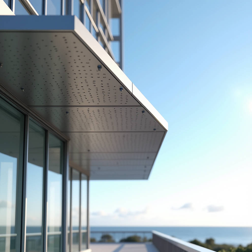
When an architect specifies perforated aluminum soffit panels on a coastal high-rise, the conversation shifts from aesthetics to physics. Wind-driven rain, salt-laden air, and cyclic negative pressure loads turn what looks like a simple horizontal closure into a high-stakes engineering decision. An Aluminum Soffit Panel in this context must do more than cover the underside of an overhang. It needs to manage airflow, resist galvanic corrosion, and maintain dimensional stability across temperature swings that can exceed 40°C between day and night on a single facade. This article examines the structural and material considerations that determine whether a ventilated soffit system performs for 30 years or becomes a maintenance liability within five. The focus is on solid extruded and brake-formed aluminum panels, typically 2.0mm to 3.0mm gauge, finished with PVDF or FEVE coatings, and engineered for mechanically fastened open-joint or interlocking installations.
Why Ventilated Soffit Design Is a Structural Problem, Not Just an Architectural One
Attic and cavity ventilation requirements drive most soffit specifications, but the structural implications rarely get the same attention as the free-air calculation. Building codes such as the International Building Code (IBC) and ASHRAE 90.1 mandate minimum net free ventilating area, often expressed as a ratio of 1:150 or 1:300 of attic floor area depending on vapor barrier placement. The perforation pattern on an Aluminum Soffit Panel directly affects the panel's effective section modulus. A 2.5mm panel with 25% open area from punched holes behaves differently under wind uplift than a solid panel of the same gauge.
Wind tunnel studies referenced in ASCE 7-22 show that soffit zones at building corners experience pressure coefficients (GCp) that can be 40% higher than field zones. When perforations are introduced, the net pressure differential across the panel decreases, but the remaining solid material must carry the full load. Engineers calculating allowable spans for perforated aluminum soffit panels should apply a reduced effective thickness based on the perforation ratio and pattern geometry. A conservative approach uses the net section modulus at the narrowest ligament between perforations, not the gross section of the panel.
Perforation Patterns and Their Effect on Load Capacity
Staggered round holes, slotted openings, and custom geometric perforations each affect stress distribution differently. Round holes in a 60-degree staggered pattern provide the most uniform stress distribution, which is why they dominate commercial specifications. Slotted perforations oriented parallel to the span direction preserve more bending stiffness than those oriented perpendicular. For a 2.5mm thick 5052-H32 aluminum soffit panel with 8mm diameter holes at 12mm center-to-center spacing (approximately 35% open area), the effective bending strength drops to roughly 55-60% of the solid panel value. This reduction must be factored into span tables provided by manufacturers like Futeng®, whose engineering teams validate these calculations against ASTM E330 uniform load testing.
Coastal Corrosion and the Case for 5052 vs. 6061 Alloys
Marine environments expose soffit panels to chloride deposition rates that can exceed 100 mg/m² per day within 500 meters of breaking surf. The alloy choice for an Aluminum Soffit Panel in these conditions is not a trivial substitution. 5052-H32 offers superior corrosion resistance in salt-laden atmospheres compared to 6061-T6, which contains copper and is more susceptible to intergranular attack. The magnesium content in 5052 (2.2-2.8%) forms a more stable passive oxide layer when exposed to chloride ions.
Testing per ASTM B117 neutral salt spray demonstrates that 5052-H32 panels with a properly applied PVDF coating system (minimum 30 microns dry film thickness, two-coat or three-coat) show no blistering or filiform corrosion after 4,000 hours. 6061-T6 under identical conditions may exhibit underfilm corrosion at cut edges and fastener holes after 2,000-3,000 hours. The cost difference between the two alloys is approximately 8-12% on a per-square-meter basis, which is negligible compared to the cost of scaffold access for premature panel replacement on a 20-story building.
Galvanic Compatibility with Support Systems
Aluminum soffit panels fastened to steel sub-structures create a galvanic cell in the presence of moisture. The aluminum (anodic) sacrifices itself to protect the steel (cathodic). This is well understood, but the practical mitigation details are often overlooked during installation. Stainless steel fasteners (grade 304 or 316) with nylon isolating washers are the minimum. For aggressive marine exposures, the aluminum sub-frame should be electrically isolated from the steel primary structure using EPDM or neoprene gaskets at all connection points. The fastener spacing itself affects the galvanic current density; tighter spacing increases the total area ratio of cathode to anode, accelerating aluminum corrosion at each fastener location.
Coating Systems: PVDF, FEVE, and the 30-Year Performance Threshold
Architectural specifications for soffit panels often default to PVDF (polyvinylidene fluoride) coatings, but the resin system alone does not determine performance. The complete coating system includes pretreatment, primer, color coat, and sometimes a clear topcoat. For Aluminum Soffit Panel applications, the pretreatment step is the most critical and the most frequently compromised. A chrome-based conversion coating per ASTM D1730 Type B or a chrome-free alternative per AAMA 2605 provides the adhesion base for subsequent layers.
FEVE (fluoroethylene vinyl ether) resin coatings offer a distinct advantage for soffit applications: they can be formulated with higher gloss retention and can be field-applied for touch-up repairs, unlike PVDF which requires factory baking at 230-250°C. FEVE coatings tested per AAMA 2605-20 show gloss retention above 50% after 10 years of South Florida exposure at 45° angle. For soffit panels that are viewed from below at oblique angles, gloss uniformity matters more than absolute gloss level. Patchy degradation from uneven coating application becomes visible because soffits are typically viewed against the sky, creating backlighting that highlights surface irregularities.
| Coating Parameter | PVDF (70% Kynar) | FEVE (Lumiflon) | Polyester (Standard) |
|---|---|---|---|
| Dry Film Thickness | 30-40 microns | 30-35 microns | 20-25 microns |
| Gloss Retention (10yr Florida) | 50-65% | 55-70% | 15-30% |
| Color Shift (ΔE, 10yr) | ≤ 5.0 | ≤ 4.0 | ≤ 12.0 |
| Salt Spray Resistance (ASTM B117) | 4,000+ hrs | 4,000+ hrs | 1,000-1,500 hrs |
| Field Touch-Up Capability | Limited | Good | Excellent |
| Typical Cost Index (per m²) | 100 | 110-120 | 55-65 |
Thermal Movement and Panel Joint Design
Aluminum expands at approximately 2.38 mm per linear meter per 100°C temperature change. A 4-meter-long soffit panel subjected to a 70°C surface temperature swing (from -10°C winter night to 60°C summer sun on a dark-colored panel) will experience roughly 6.7 mm of linear movement. If the panel is rigidly fixed at both ends, this movement converts to compressive stress that can cause buckling, or tensile stress that can cause fastener tear-out.
The joint design must accommodate this movement while maintaining the visual alignment that architects expect. Open-joint systems with 10-15 mm gaps inherently absorb thermal movement. Interlocking systems require slip joints at regular intervals, typically every 3-4 meters for dark-colored panels and every 5-6 meters for light-colored panels. The coefficient of thermal expansion for 5052 aluminum is 23.8 × 10⁻⁶ /°C, slightly lower than 6061 at 23.6 × 10⁻⁶ /°C, but the difference is negligible for joint design purposes.
Concealed Fastener vs. Exposed Fastener Systems
Concealed fastener soffit systems use clips or carrier rails that engage the panel edges, leaving the visible surface clean. The trade-off is that each clip must be engineered to carry the design wind load while allowing thermal slip. Clip spacing is typically 300-600 mm on center, and the clip material should match the panel alloy to avoid galvanic issues. Exposed fastener systems are simpler and less expensive to install, but each fastener penetration is a potential corrosion initiation point. For exposed fastener soffits in marine environments, the fasteners should be 316 stainless steel with EPDM sealing washers, and the panel should be pre-drilled with clearance holes that allow for thermal movement without binding.
Fire Performance and Building Code Compliance
Exterior soffit panels fall under the requirements of IBC Chapter 26 and NFPA 285 for multi-story buildings. Solid aluminum panels are non-combustible per ASTM E136, which simplifies compliance compared to combustible core materials. However, the coating system and any insulation behind the soffit must also be considered in the assembly fire rating. AAMA 714 provides guidelines for liquid-applied coatings on aluminum, and coatings with high organic content may contribute to flame spread if not properly tested.
For buildings over 12 meters in height, many jurisdictions require that exterior cladding components, including soffits, meet limited combustibility criteria. Solid aluminum with PVDF or FEVE coatings typically satisfies these requirements, but the project specification should explicitly reference the relevant test standards: ASTM E84 for surface burning characteristics, ASTM E136 for non-combustibility, and NFPA 285 for multi-story assembly testing where applicable.
Installation Sequencing and Trade Coordination
Soffit installation sits at the intersection of multiple trades: roofing, curtain wall, structural steel, and mechanical. The sequence matters. If the curtain wall is installed before the soffit, the panel edge termination at the head of the window system must be detailed for a blind connection. If the soffit goes in first, the curtain wall installer must coordinate head flashings that lap over the soffit edge trim.
On a typical commercial project, soffit panels are installed after the roof membrane and before the wall cladding at the parapet level. This allows the soffit to be tucked behind the fascia and provides a clean drip edge. The panel layout should be dimensioned from the building control lines, not from the structural steel, because steel erection tolerances (±6 mm in any direction per AISC 303) exceed the joint width tolerance of a typical architectural soffit system (±2 mm). Laser scanning the as-built structure before panel fabrication is becoming standard practice on projects where the soffit panels are pre-fabricated to final dimensions.
Cost Drivers Beyond Material Price
The per-square-meter cost of the aluminum sheet is only one component. Perforation adds 15-25% to the panel cost depending on open area percentage and pattern complexity. Custom RAL or Pantone color matching adds 10-15% compared to standard color ranges. The support system, including aluminum or galvanized steel sub-girts, clips, and fasteners, typically represents 30-40% of the total installed soffit cost. Site labor for soffit installation runs higher than wall panel installation because of the overhead working position; productivity rates of 8-12 m² per installer per day are typical for concealed fastener systems, compared to 15-20 m² for wall panels.
When evaluating total installed cost, the panel gauge decision has compounding effects. A 2.0mm panel may require closer support spacing than a 3.0mm panel, which increases the linear meters of sub-structure per square meter of soffit area. The optimal balance depends on the specific span conditions and wind loads. For a project with 1.2-meter support spacing and moderate wind loads (design pressure of 1.5 kPa), a 2.5mm 5052-H32 panel often represents the cost-performance sweet spot. Suppliers like Futeng® provide span tables backed by ASTM E330 testing that help specifiers make these trade-offs with data rather than rules of thumb.
Quality Verification: What to Check Before Panels Leave the Factory
Third-party inspection of aluminum soffit panels should verify coating thickness (ASTM D7091), color consistency (ASTM D2244, ΔE ≤ 2.0 for adjacent panels), panel flatness (maximum deviation of 0.8% of the diagonal dimension per AAMA 609), and dimensional tolerances (length and width ±1.5 mm, squareness within 2 mm per meter of diagonal). For perforated panels, the hole pattern alignment across panel joints should be verified by laying up adjacent panels on a flat surface and checking that the pattern registers within ±1 mm.
Coating adhesion testing per ASTM D3359 Method B (cross-hatch) should achieve a rating of 5B, meaning no coating removal. Impact resistance per ASTM D2794 should show no cracking or delamination at 1.8 N·m reverse impact. These tests are not expensive and can be performed on retained samples from each production batch. The cost of a single scaffold drop for remedial work on a completed building far exceeds the cost of thorough factory inspection.
Specifying for Long-Term Performance
The specification for an Aluminum Soffit Panel system should address alloy, temper, gauge, perforation pattern and open area, coating system with pretreatment, fastener material and finish, support system material and corrosion protection, joint type and movement accommodation, and testing requirements. Leaving any of these items to the installer's discretion invites value engineering that may compromise the system's durability. A well-drafted specification references specific ASTM, AAMA, and ASCE standards and requires submittal of test reports and calculations before fabrication begins.
The difference between a soffit system that performs for three decades and one that requires intervention within five years is rarely the aluminum itself. It is the engineering that surrounds the aluminum: the joint that accommodates thermal movement, the fastener that resists galvanic corrosion, the coating that withstands UV and salt, and the support system that maintains panel alignment under cyclic wind loading. Solid aluminum soffit panels, properly specified and installed, deliver that performance. The responsibility lies with the specifier to understand and address each of these technical dimensions.
For projects requiring engineering support on solid aluminum soffit panel systems, including custom span tables and wind load calculations, Futeng® provides technical documentation aligned with ASTM and AAMA standards. Contact their engineering team with project-specific parameters for a detailed assessment.