Aluminum Fascia Panel Engineering Guide for Commercial Building Envelope Performance
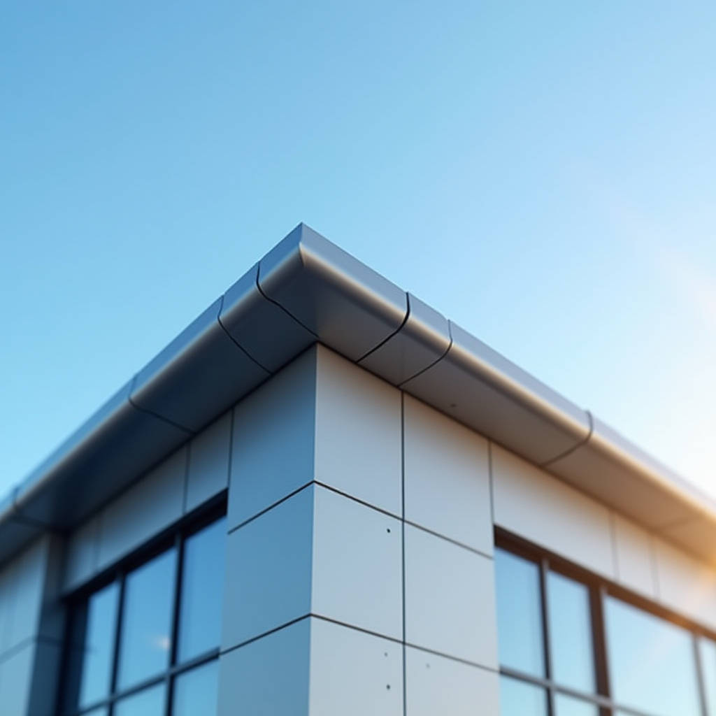
When a commercial building envelope fails at the roofline, the culprit is rarely the roofing membrane itself. More often, water finds its way in through the transition point where the roof meets the vertical wall — precisely where the fascia board lives. An Aluminum Fascia Panel solves this junction problem permanently when specified correctly, but the specification process itself trips up even experienced contractors. The difference between a fascia system that performs for 30 years and one that warps within three seasons comes down to alloy selection, attachment engineering, and understanding how thermal movement behaves at the perimeter edge. This piece covers the technical decisions that determine whether your fascia performs or fails — from 3003 versus 5052 alloy selection to the fastener slotting calculations most shop drawings overlook.
What Separates a Structural Fascia Panel from Decorative Trim
The residential market has blurred the definition of aluminum fascia. Walk through any home improvement store and you will find thin-gauge coil stock — typically 0.019 to 0.024 inches — marketed as aluminum fascia. These products serve a legitimate purpose for residential drip edges and porch soffits. They are not what commercial building envelopes require.
A properly specified Aluminum Fascia Panel for commercial and institutional work starts at 0.080 inches (2.0mm) and goes up from there. The distinction matters because fascia on a commercial building performs multiple structural functions simultaneously: it resists wind uplift at the roof perimeter, transfers lateral loads from the parapet wall, accommodates differential movement between the roof deck and wall assembly, and provides the primary drainage plane for the roof edge. A 0.024-inch residential coil cannot do any of these things.
The engineering reality is straightforward. At 0.080 inches, a 5052-H32 aluminum fascia panel carries a yield strength of approximately 28,000 psi. When you calculate the section modulus of a typical L-shaped fascia profile spanning 48 inches between supports, the panel can resist roughly 35 psf of wind load — adequate for most low-rise commercial applications. Step up to 0.125 inches (3.0mm) and you are looking at nearly 55 psf capacity, which covers high-rise perimeter conditions where wind pressures concentrate. These numbers are not theoretical. They come directly from ASTM E330 testing protocols that reputable manufacturers use to validate their systems.
"The fascia is the most thermally active component in the entire building envelope. It sits at the intersection of three different movement planes — the roof deck, the wall, and the soffit — and it has to accommodate all of them simultaneously without buckling." — Building Envelope Consultant, Chicago IL
3003 vs 5052: The Alloy Decision That Determines Service Life
Most aluminum fascia on the market uses 3003-H14 alloy. It forms easily, costs less, and welds without complication. For interior soffits or protected ceiling applications, 3003 works fine. For exterior fascia panels exposed to direct sun, wind, and thermal cycling, 5052-H32 is the correct call.
The performance gap between these two alloys widens considerably under real-world conditions. 5052-H32 delivers roughly 40% higher tensile strength than 3003-H14 — 31,000 psi versus 22,000 psi. More importantly for fascia applications, 5052 has superior corrosion resistance in marine and industrial atmospheres. The magnesium content in 5052 (2.2-2.8%) forms a more stable oxide layer than the manganese in 3003 (1.0-1.5%). This difference shows up in salt spray testing per ASTM B117, where 5052 panels consistently outlast 3003 by a factor of 1.5 to 2.0 in coastal environments.
The cost difference between 3003 and 5052 is real — typically 12-18% premium for 5052 on a per-pound basis. But when you factor in the total installed cost of a fascia system, including access equipment, labor, and the disruption of replacing failed panels, the alloy upgrade represents less than 3% of the total project cost. For buildings within 5 miles of saltwater or industrial emissions, 5052 should be treated as the minimum specification, not an upgrade.
| Property | 3003-H14 | 5052-H32 | Relevance to Fascia |
|---|---|---|---|
| Tensile Strength (psi) | 22,000 | 31,000 | Wind load resistance at roof edge |
| Yield Strength (psi) | 21,000 | 28,000 | Resistance to permanent deformation |
| Elongation (%) | 8-16 | 7-12 | Formability for complex profiles |
| Corrosion Resistance | Good | Excellent | Coastal and industrial environments |
| Thermal Expansion (in/in/°F) | 0.0000129 | 0.0000132 | Joint design and slotting |
| Relative Cost | Base | +12-18% | Material budget impact |
Thermal Movement: The Calculation Most Shop Drawings Miss
Aluminum moves. A 20-foot length of aluminum fascia panel subjected to a 100°F temperature swing — from a cold winter night to direct summer sun — will expand by approximately 0.31 inches. That is not a rounding error. If the attachment system does not accommodate that movement, the panel will buckle, the fasteners will elongate their holes, or the joints will open up and let water through.
The calculation is straightforward: ΔL = α × L × ΔT. For aluminum, α = 0.0000129 in/in/°F. For a 20-foot panel (240 inches) with a 100°F temperature swing: 0.0000129 × 240 × 100 = 0.31 inches. This means every joint in the fascia system needs at least 3/8 inch of movement capacity, and every fastener through the panel needs to be in a slotted hole oriented in the direction of expansion.
The most common failure mode in aluminum fascia installations is fasteners that are too tight. A contractor installs a 20-foot panel, drives the fasteners home with an impact driver, and creates a rigid connection at every attachment point. When the panel heats up, it has nowhere to go. The result is oil-canning — visible waves and distortions in the panel face — or, in severe cases, fastener pull-through where the panel tears around the screw head. Both failures are entirely preventable with proper slotting details and torque specifications.
Futeng® has addressed this in their standard fascia system by pre-punching slotted holes at 16-inch centers, sized for #14 fasteners with 3/8-inch longitudinal travel. The slot geometry accommodates the full thermal range for panel lengths up to 24 feet, which covers the vast majority of commercial fascia applications without requiring field modification.
PVDF Coatings: Understanding the 70% Resin Rule
Not all architectural coatings are equal, and the fascia panel is the worst place on a building to discover this. Fascia panels sit at the roofline where UV exposure is most intense, where water cascades off the roof surface, and where dirt and pollutants accumulate. A coating that performs adequately on a vertical wall may fail within five years on a fascia panel.
The industry standard for premium architectural aluminum finishes is AAMA 2605, which governs high-performance PVDF (polyvinylidene fluoride) coatings. The critical specification within AAMA 2605 is the 70% PVDF resin content requirement. Coatings with less than 70% PVDF resin — typically Kynar 500® or Hylar 5000® — will not meet AAMA 2605 and should not be specified for exterior fascia applications. The resin content directly determines UV resistance, chalk resistance, and color retention.
A proper PVDF coating system for aluminum fascia consists of three layers: a chrome-based pretreatment conversion coating, a corrosion-resistant primer at 0.2-0.3 mils, and a color coat at 1.0-1.2 mils with minimum 70% PVDF resin. Some manufacturers add a clear topcoat for additional UV protection, particularly for bright colors and metallics. The total dry film thickness should be 1.2-1.5 mils minimum per AAMA 2605.
Testing requirements under AAMA 2605 include 4,000 hours of salt spray resistance (ASTM B117), 4,000 hours of humidity resistance (ASTM D2247), and 10 years of South Florida exposure with maximum 5 Delta E color change and 8 gloss unit reduction. These are rigorous standards, and they are the reason why properly coated aluminum fascia panels from qualified manufacturers carry 20-30 year finish warranties.
Wind Load Design at the Roof Perimeter
The roof perimeter is the most aerodynamically active zone on any building. ASCE 7 defines the roof perimeter as the zone extending inward from the roof edge a distance equal to 10% of the least horizontal building dimension, but not less than 3 feet. In this zone, wind pressures are 1.5 to 2.5 times higher than in the field of the roof, depending on building geometry and exposure category.
For fascia panel design, this means the panel and its attachments must resist negative pressures (suction) that want to pull the fascia away from the building. A typical commercial building in a 115 mph wind zone (Risk Category II) might see roof perimeter pressures of -45 to -65 psf. The fascia panel spanning between supports must handle this load without exceeding its allowable deflection, typically L/60 for metal panels per AAMA 508.
The attachment calculation is equally critical. A single #14 self-drilling screw into 16-gauge steel substrate has a pull-out capacity of roughly 400-500 pounds in tension. At 16 inches on center, that gives you approximately 300-375 pounds per linear foot of attachment capacity. With a 24-inch fascia panel height, that translates to 150-188 psf of wind resistance — adequate for most conditions but requiring verification for high-wind zones and tall buildings where corner pressures can exceed 200 psf.
For projects in hurricane-prone regions, the fascia panel attachment should be engineered to resist the specific wind speeds and exposure categories defined in the project's structural drawings. This typically means closer fastener spacing at corners (12 inches or less), heavier gauge substrate, and potentially thicker fascia panels to handle the increased loads.
Substrate Compatibility and Galvanic Corrosion
Aluminum fascia panels rarely attach directly to aluminum. More commonly, they fasten to steel framing, wood blocking, or concrete substrates. Each of these material combinations creates a galvanic cell, and the aluminum will always be the anode — meaning it will corrode preferentially to protect the more noble metal.
The galvanic series tells the story. Aluminum sits at approximately -0.75 to -0.90 volts on the galvanic scale, while steel sits at -0.35 to -0.45 volts. The 0.4-volt difference is enough to drive corrosion in the presence of an electrolyte — which, on a building exterior, means any moisture. The solution is to break the electrical circuit between the two metals.
For aluminum fascia panels over steel framing, the minimum separation requirement is a 1/8-inch thick isolating tape or gasket between the panel and the steel. The fasteners themselves should be stainless steel (300 series) rather than carbon steel, and fastener heads should be isolated from the aluminum panel face with nylon washers. These details are specified in AAMA TIR-A9, which covers metal-to-metal contact in architectural applications.
Wood substrates present a different problem. Pressure-treated lumber contains copper compounds that are aggressively corrosive to aluminum. Even cedar and redwood contain tannic acids that can etch the aluminum surface. The separation barrier between aluminum fascia and any wood substrate should be a minimum 30-pound building felt or a synthetic underlayment rated for metal contact. Direct aluminum-to-wood contact is never acceptable in exterior applications.
Fabrication Tolerances and Shop Drawing Review
The difference between a fascia system that installs smoothly and one that requires field modification on a swing stage comes down to fabrication tolerances. Aluminum fascia panels should be fabricated to the tolerances defined in AAMA 609.1, which specifies ±1/16 inch for panel dimensions up to 12 feet and ±1/8 inch for panels 12 to 24 feet. Hole locations should be within ±1/32 inch of the specified position.
These tolerances seem tight, and they are. But consider the cumulative effect: a 20-foot fascia panel with a 1/8-inch length error combined with a 1/16-inch hole location error at each end means the panel might not align with its pre-installed substrate fasteners. On the ground, you can fudge it. On a swing stage 80 feet up, you cannot.
Shop drawing review is where these issues get caught — or missed. The review should verify that panel dimensions match the substrate layout, that joint locations align with the building's structural grid, that expansion joints are provided at the correct intervals (typically every 30-40 feet for aluminum fascia), and that the attachment pattern matches the structural engineer's wind load requirements. A thorough shop drawing review takes time, but it is far cheaper than resolving coordination problems in the field.
Installation Sequencing and the Critical Path
Fascia panel installation sits at an awkward point in the construction sequence. The roof needs to be substantially complete before fascia can be installed, because the fascia covers the roof edge. But the wall cladding below the fascia also needs to be complete, because the fascia laps over it. And the soffit needs to be in place, because the fascia closes the soffit edge. Getting all three trades coordinated at the same time is a scheduling challenge that general contractors consistently underestimate.
The practical solution is to treat fascia installation as a separate mobilization. The roofing contractor installs the roof membrane and edge metal up to the point where fascia will cover it. The wall cladding contractor completes the wall panels up to the fascia line. The soffit contractor installs the soffit panels. Then, and only then, the fascia contractor mobilizes to install the aluminum fascia panels that tie all three systems together. This sequence adds a week to the schedule compared to trying to do everything simultaneously, but it eliminates the rework that inevitably occurs when trades conflict.
For design-build projects, specifying the fascia system early allows the design team to coordinate the critical interfaces — the roof edge detail, the wall-to-fascia transition, and the soffit connection — before any material is fabricated. The ANSI/FM 4474 standard for roof perimeter systems provides useful guidance on these interface details, particularly for wind uplift resistance at the fascia-to-roof connection.
Cost Drivers Beyond the Per-Square-Foot Price
The per-square-foot material cost of an aluminum fascia panel is the starting point, not the ending point. Several factors drive the total installed cost well beyond the base material price, and understanding these helps explain why fascia bids can vary by 50% or more between contractors.
Panel complexity is the biggest cost driver. A simple flat fascia panel with a single 90-degree bend at the bottom is inexpensive to fabricate. Add a drip edge, a return leg, stiffening ribs, and a custom profile, and the fabrication cost can triple. The number of pieces matters too — a 200-foot building elevation with 20-foot panels means 10 panels and 9 joints. The same elevation with 10-foot panels means 20 panels and 19 joints, nearly doubling the labor for joint treatment and alignment.
Access is the second major cost driver. Fascia panels installed from the ground on a one-story building involve minimal access cost. The same panels installed 100 feet up on a building with no setback require swing stages or boom lifts, adding $2-5 per square foot to the installation cost. Buildings with complex geometries, multiple setbacks, or limited access on all sides push these costs higher still.
Finish requirements also affect cost. Standard PVDF colors (whites, grays, tans) are the most economical. Custom colors, metallics, and bright colors require additional coating steps and carry higher material costs. A custom metallic PVDF finish can add 20-30% to the panel cost compared to a standard color. The AAMA finish standard should be specified clearly in the contract documents to avoid substitution of lower-quality coatings.
Quality Verification: What to Check Before Panels Leave the Factory
Factory inspection of aluminum fascia panels before they ship prevents the discovery of problems at the job site, where remedies are expensive and schedule impacts are severe. The inspection should cover dimensional accuracy, coating quality, and packaging.
Dimensional checks should verify panel length, width, and squareness against the approved shop drawings. A panel that is out of square by 1/16 inch over 2 feet will be out by 5/8 inch over 20 feet — enough to create a visible gap at the joint. Coating checks should include dry film thickness measurements at multiple points per panel, color verification against the approved sample under controlled lighting, and visual inspection for defects such as orange peel, blistering, or dirt inclusion in the coating.
Packaging is often overlooked but critical. Aluminum fascia panels should be individually interleaved with protective film or paper, stacked on edge in a purpose-built crate, and shipped with the panels oriented vertically to prevent sagging. Panels shipped flat and stacked can develop permanent deformation from their own weight, particularly on long-haul shipments. The ASTM B209 standard for aluminum sheet provides guidance on proper handling and storage of aluminum products.
For large projects, a pre-installation meeting with the fascia contractor, the general contractor, and the manufacturer's representative is standard practice. This meeting should review the approved submittals, confirm the installation sequence, verify that all interface conditions are ready, and establish the quality control procedures for the installation. The Metal Building Manufacturers Association (MBMA) provides useful guidelines for these pre-installation coordination procedures.
Getting the fascia right matters because the roofline is the most visible, most weather-exposed, and most thermally active component of the building envelope. The engineering decisions — alloy selection, coating specification, thermal movement accommodation, attachment design — determine whether the fascia performs quietly for decades or becomes a source of leaks, callbacks, and warranty claims. Specifying correctly at the outset costs marginally more than getting it wrong and fixing it later.