LED Aluminum Facade Engineering Guide for Solid Cladding Integration and Thermal Performance
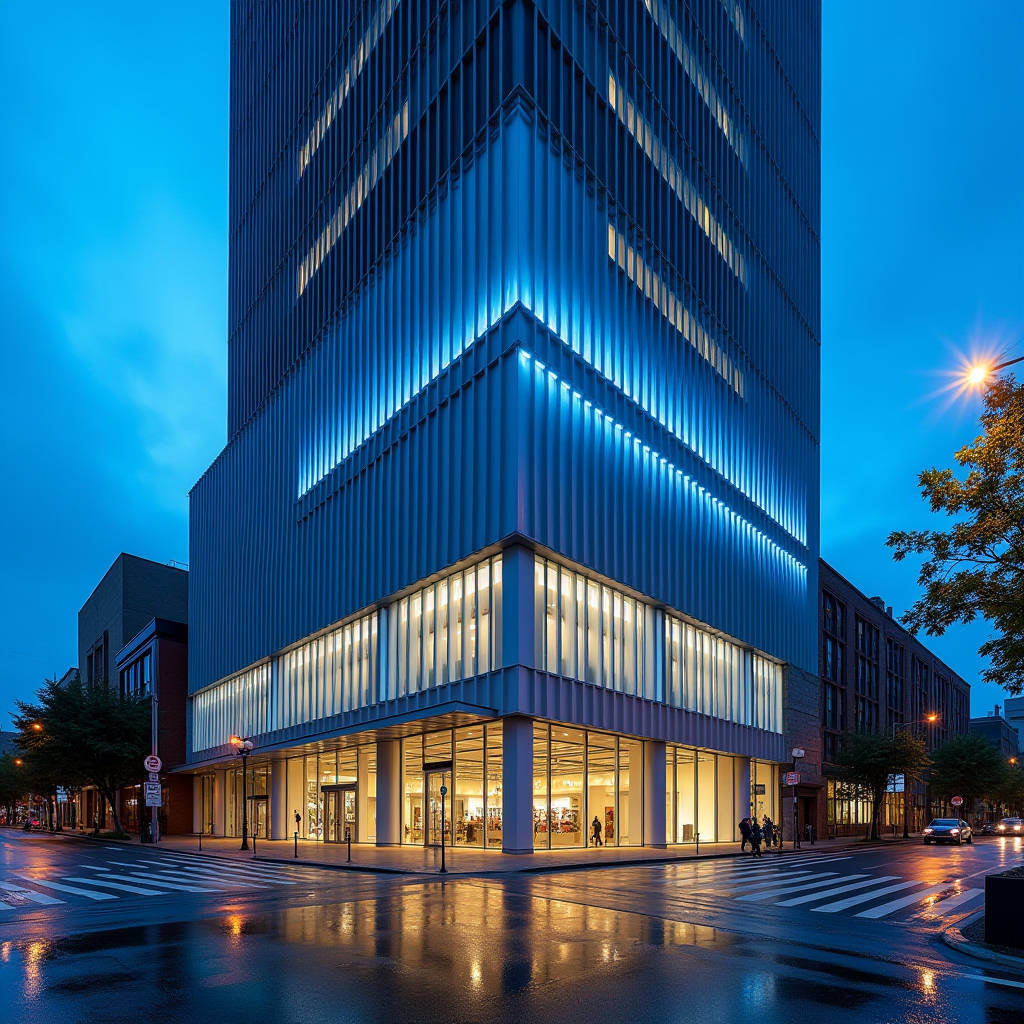
Integrating LED lighting into solid aluminum cladding systems has moved from a niche architectural gesture to a standard specification on commercial towers, hospitality venues, and transit hubs. The term LED Aluminum Facade describes a building envelope where LED luminaires are embedded within, mounted onto, or synchronized with solid aluminum panels to create a dynamic, illuminated skin. This approach eliminates the visual clutter of externally attached fixtures and allows the facade itself to become the light source. For contractors and facade consultants, the challenge sits at the intersection of two trades: precision metal fabrication and high-performance LED engineering. Getting the waterproofing wrong means water ingress behind the cladding. Getting the thermal management wrong means premature LED failure inside a sealed 3.0mm aluminum panel. Getting the structural load calculations wrong means a facade that looks impressive at handover but becomes a maintenance liability within two years. This article addresses the engineering decisions that determine whether an LED aluminum facade performs reliably across a 15-year service life, with a focus on panel integration methods, driver accessibility, heat dissipation, and compliance with IEC 60529 and AAMA 2605.
Understanding the Integration Hierarchy: Surface-Mounted vs. Embedded vs. Perforated Backlighting
Not all LED aluminum facade systems are created equal. The integration method directly affects buildability, waterproofing strategy, and long-term maintenance access. Three distinct approaches dominate the market, and each carries its own set of fabrication and installation implications.
Surface-Mounted LED Profiles on Solid Aluminum Panels. This is the most common approach for retrofit projects and mid-budget new builds. Linear LED aluminum profiles—typically extruded 6063-T5 channels with polycarbonate diffusers—are mechanically fastened to the face of pre-installed solid aluminum cladding panels. The aluminum panel itself remains structurally unchanged. The LED driver and cabling sit behind the panel in the drained cavity, with wiring passing through grommeted penetrations. The advantage is straightforward: panel fabrication is standard, and LED profiles can be sourced separately. The disadvantage is that the profile creates a shadow line and a dust trap on the panel face. In coastal environments, salt spray can accumulate in the gap between the profile and the panel, accelerating localized corrosion if the panel coating is scratched during profile installation.
Embedded Integration with CNC-Routed Panel Recesses. Here, the solid aluminum panel is CNC-routed to create a recessed channel that accepts the LED profile flush with the panel surface. The panel thickness must be at least 2.5mm to retain structural integrity after routing, and the routing depth is typically limited to 1.2–1.5mm to avoid compromising the panel's wind-load resistance. The LED profile is bonded and mechanically clipped into the recess. This method delivers a clean, architectural finish with no protruding elements. However, it demands tight coordination between the panel fabricator and the LED supplier: the routed channel width must match the profile tolerance within ±0.3mm, and the PVDF coating must be applied after routing to ensure the exposed aluminum edge inside the channel is fully sealed.
Perforated Backlit Panels with Internal LED Arrays. This is the premium approach seen on landmark projects. The solid aluminum panel is perforated with a custom pattern—circular holes, geometric shapes, or parametric designs—and LED modules are mounted behind the panel on a secondary support frame within the ventilated cavity. The light shines through the perforations, creating a pointillist lighting effect. The panel itself acts as a light shield, and the perforation density determines the perceived brightness. This method requires careful coordination of perforation diameter (typically 3mm to 8mm), pitch, and open-area ratio (usually 15% to 35%) against the LED module spacing and lumen output. The key engineering challenge is maintaining the panel's flatness tolerance after perforation: the perforation process relieves internal stresses in the aluminum sheet, which can cause warping if the panel is not stress-relieved before cutting.
On a 2023 mixed-use tower in Kuala Lumpur, the project team switched from surface-mounted profiles to embedded integration midway through shop drawings. The change required re-routing 1,200 panels at the fabricator's facility and added 18 days to the fabrication schedule. The lesson: integration method must be locked at the design development stage, not value-engineered during procurement.
Thermal Management: Why LED Longevity Depends on the Aluminum Panel
LED junction temperature is the single biggest determinant of lumen maintenance and driver lifespan. In an LED aluminum facade, the solid aluminum panel itself can serve as a heat sink—but only if the thermal path is engineered correctly. A 3.0mm solid aluminum panel has a thermal conductivity of approximately 205 W/m·K (for 3003-H14 alloy), which is significantly higher than the 0.3–0.5 W/m·K of ACM core materials. This makes solid aluminum the superior substrate for dissipating LED heat.
The critical factor is the thermal interface between the LED module's aluminum PCB board and the back face of the cladding panel. If the LED module is simply screwed to the panel with an air gap, the thermal resistance at the interface can exceed 5°C/W, causing the LED junction temperature to spike 15–20°C above ambient. Over a 50,000-hour operating life, this temperature differential can reduce lumen output by 30% compared to a properly bonded installation.
The recommended practice is to use a thermally conductive gap filler—typically a silicone-based pad with 1.5–3.0 W/m·K conductivity—compressed between the LED module and the panel. This reduces interface thermal resistance to below 0.5°C/W. For embedded installations, the aluminum profile that houses the LED strip should be in full surface contact with the routed channel, with thermal paste applied along the contact area.
Ambient temperature derating must also be factored into the LED driver specification. In Middle Eastern and Southeast Asian markets, where daytime ambient temperatures can reach 50°C and the cavity behind a dark-colored aluminum panel can exceed 70°C, standard LED drivers rated for 45°C ambient will fail within 18–24 months. Drivers specified for LED aluminum facade applications in these climates should be rated for 65°C ambient minimum, with output current derating curves reviewed against the project's worst-case cavity temperature.
| Parameter | Surface-Mounted | Embedded (CNC Routed) | Perforated Backlit |
|---|---|---|---|
| Panel Thickness Required | 2.0mm minimum | 2.5mm minimum | 2.5–3.0mm |
| Thermal Path to Panel | Through fasteners only | Full surface contact with thermal paste | LED module on separate frame; panel acts as shield |
| Typical Interface Thermal Resistance | 3–5°C/W | 0.3–0.8°C/W | N/A (decoupled) |
| Waterproofing Strategy | Grommeted cable penetrations | Sealed channel + IP65 driver enclosure | Drained cavity + IP67 LED modules |
| Driver Accessibility | Accessible from cavity (panel removal) | Requires LED profile extraction | Accessible from cavity |
| Perceived Brightness Control | Fixed by LED output | Fixed by LED output | Adjustable via perforation density |
| Fabrication Complexity | Low | Medium–High | High |
| Cost Index (Relative) | 1.0x | 1.4–1.7x | 2.0–2.8x |
Waterproofing and Ingress Protection: The IP Rating Alone Is Not Enough
Specifying IP65 or IP67 LED luminaires for an LED aluminum facade is necessary but insufficient. The IP rating of the luminaire addresses the enclosure's resistance to water and dust ingress, but it does not address the penetration points where cables pass through the aluminum panel, the condensation risk within the cavity, or the drainage of water that inevitably enters the system over time.
The IEC 60529 standard defines IP ratings, but facade engineers should also reference AAMA 501.1 for dynamic water penetration testing of the complete wall assembly, including the cladding, the LED integration points, and the air-and-water barrier behind the cavity. A luminaire that passes IP67 submersion testing in a lab can still be the entry point for water if the cable gland is not properly torqued or if the panel penetration is not sealed with a UV-stable grommet.
For embedded LED aluminum facade systems, the routed channel itself becomes a potential water trap. If the channel is oriented horizontally and exposed to driving rain, water can pool in the channel and seep past the LED profile's end caps. The solution is twofold: first, specify that all horizontal routed channels include a 2° minimum slope toward a drainage point; second, apply a bead of neutral-cure silicone sealant along the full length of the profile-to-panel interface, tooled to create a positive weather seal. The sealant must be compatible with the PVDF coating—acetoxy-cure silicones can etch certain PVDF formulations, so neutral-cure is mandatory.
Condensation within the ventilated cavity behind the aluminum panel is another persistent issue. In humid climates, the temperature differential between the air-conditioned interior and the warm, humid exterior air can cause condensation to form on the back face of the panel. If this condensation drips onto LED drivers or connection terminals, corrosion and short circuits follow. The cavity design should include a continuous drainage plane at the base of each floor level, and LED drivers should be mounted on stand-off brackets that keep them at least 50mm above the drainage plane.
Structural Considerations: Wind Load, Panel Stiffness, and Dynamic Fatigue
Adding LED elements to an aluminum facade changes the structural behavior of the cladding system in ways that are often overlooked during value engineering. A surface-mounted LED profile adds 0.8–1.5 kg per linear meter to the panel. For a 1,200mm × 3,000mm panel with five horizontal LED runs, that is an additional 4.5–6.8 kg of dead load. This may seem trivial, but when multiplied across 5,000 panels on a high-rise, the cumulative load on the support structure and anchors becomes significant.
More importantly, the LED integration method affects the panel's effective section modulus. A 2.5mm solid aluminum panel with a CNC-routed channel has reduced bending stiffness along the routed axis. The panel's wind-load capacity should be recalculated based on the reduced cross-section at the routed locations, not the full panel thickness. For projects in typhoon-prone regions, where design wind pressures can exceed 3.0 kPa, the routing depth and pattern must be validated through finite element analysis or physical load testing per ASTM E330.
Dynamic fatigue is another concern. LED aluminum facades on tall buildings are subject to vortex shedding and wind-induced vibration. The repeated cyclic loading can cause loosening of the LED profile fasteners over time. Nyloc nuts, thread-locking compounds, or rivet-based fastening systems should be specified for all LED-to-panel connections. Self-tapping screws into aluminum without a locking mechanism will back out under vibration, and the resulting loose profile can rattle audibly and damage the panel coating.
For perforated backlit panels, the perforation pattern itself must be engineered to avoid creating stress concentration points. Circular perforations are preferred over sharp-cornered shapes because they distribute stress more evenly. The minimum web width between perforations—the remaining solid aluminum between adjacent holes—should be at least 1.5 times the material thickness to prevent tear-out under wind suction loads.
Driver Placement, Wiring Topology, and Maintenance Access
The LED driver is the component most likely to fail in an LED aluminum facade system. Electrolytic capacitors inside the driver degrade over time, and the mean time between failures (MTBF) for even high-quality drivers is typically 50,000 to 70,000 hours—roughly 6 to 8 years of continuous nighttime operation. This means at least one driver replacement cycle during the facade's 25-year design life must be planned for from day one.
Driver placement falls into two strategies: distributed and centralized. In a distributed topology, each panel or small group of panels has a dedicated driver mounted in the cavity directly behind the panel. The advantage is shorter low-voltage DC cable runs, which reduces voltage drop and allows smaller-gauge wiring. The disadvantage is that accessing a failed driver requires removing the specific aluminum panel behind which it is mounted. On a high-rise, this means rope access or a swing stage, and the panel removal process risks damaging the interlocking joints and the PVDF coating.
In a centralized topology, drivers are grouped in accessible electrical rooms on each floor, with longer DC cable runs to the LED luminaires on the facade. This makes driver replacement a simple indoor task, but the longer cable runs introduce voltage drop that must be compensated with larger-gauge wiring or higher driver output voltage. For cable runs exceeding 15 meters, 24V DC systems experience significant voltage drop; 48V DC systems are increasingly preferred for centralized LED aluminum facade installations because they halve the current for the same power, reducing voltage drop and cable cost.
Wiring within the ventilated cavity must be rated for the maximum cavity temperature, not just the ambient exterior temperature. XLPE-insulated cables rated for 90°C continuous operation are recommended. All connections should be made with IP67-rated junction boxes, and the junction boxes should be mounted with a drip loop in the cable to prevent water from tracking along the cable into the connector.
Coating Compatibility and Corrosion Protection for Coastal LED Facades
The combination of aluminum panels, LED electronics, and marine environments creates a galvanic corrosion risk that must be actively managed. The aluminum panel itself is protected by its PVDF or FEVE coating system, but the fasteners, brackets, and LED housing materials that contact the panel can create galvanic couples if the wrong materials are specified.
PVDF coatings applied to solid aluminum panels for LED aluminum facade applications should meet AAMA 2605 specifications, which require a minimum 70% PVDF resin content and a total dry film thickness of 30–40μm for a three-coat system. For coastal projects within 500 meters of breaking surf, a four-coat system with a corrosion-resistant primer is recommended, and the coating should be tested to ASTM B117 salt spray resistance for a minimum of 4,000 hours.
Stainless steel fasteners (grade 316, not 304) should be used for all LED profile attachments to the aluminum panel. 304 stainless steel is susceptible to pitting corrosion in chloride-rich environments, and the small fasteners used for LED profiles have a high surface-area-to-volume ratio that accelerates corrosion. The use of nylon insulating washers between stainless fasteners and the aluminum panel is recommended to break the galvanic circuit, though this adds a step to the installation process that must be enforced through quality control.
For the LED profile itself, extruded aluminum with an anodized finish (Class I architectural anodizing per AAMA 611) provides good corrosion resistance. However, anodized aluminum in direct contact with a PVDF-coated panel in a marine environment can still develop white corrosion products at the interface. Applying a thin layer of dielectric tape or a neutral-cure sealant at the contact interface eliminates this risk.
Control Systems, DMX Protocols, and Facade-Wide Synchronization
An LED aluminum facade on a commercial building is rarely a static installation. Dynamic color-changing sequences, animated patterns, and integration with building management systems require a control architecture that is specified early in the design process. Retrofitting control capabilities after the facade is installed is exponentially more expensive.
The industry standard for architectural LED control is DMX512-A, which allows 512 channels per universe and supports daisy-chain topology. For a facade with 2,000 individually addressable LED nodes, each consuming 3 channels (RGB), the system requires 12 DMX universes. The DMX controllers must be networked via Ethernet (Art-Net or sACN protocol) to a central control server that runs the lighting show software.
For large-scale LED aluminum facade installations, the control system should be specified with the following capabilities: pixel-mapping of the facade geometry so that animations appear correctly across panel joints and building corners; sunrise/sunset-based scheduling with astronomical time clock functionality; and integration with the building's fire alarm system to override the LED display with emergency lighting patterns when required by local fire codes.
Data cabling for DMX runs should use shielded twisted-pair cable (Belden 9841 or equivalent), and the cable routing should maintain at least 300mm separation from AC power cables to avoid electromagnetic interference that causes flickering. DMX signal repeaters should be installed at intervals not exceeding 300 meters, and the last fixture on each DMX chain must have a 120-ohm termination resistor to prevent signal reflection.
Procurement Strategy: Single-Source vs. Multi-Vendor Coordination
One of the most consequential decisions for a project team is whether to procure the aluminum cladding panels and the LED system from separate suppliers or to engage a single integrator. Each approach has distinct risk profiles.
Multi-vendor procurement is common because few companies manufacture both solid aluminum panels and LED luminaires. The general contractor or facade subcontractor coordinates between the panel fabricator and the LED supplier. The risk is that interface details—the routed channel dimensions, the fastener locations, the cable penetration points—fall into the gap between the two scopes. When the panels arrive on site and the LED profiles do not fit the routed channels, the resulting finger-pointing can delay the project by weeks.
Single-source integration through a specialist facade contractor who takes responsibility for both the aluminum panels and the LED system eliminates the coordination risk but typically comes at a 10–15% cost premium. For projects where the LED aluminum facade is a signature architectural feature, this premium is often justified by the reduced site coordination risk and the single point of warranty responsibility.
Futeng® is one supplier that has demonstrated capability in delivering solid aluminum cladding panels with factory-integrated LED routing and perforation, providing a single-source solution for projects in Southeast Asia and the Middle East. The key evaluation criterion when assessing any integrator is whether they have in-house CNC routing capability and whether their quality control process includes a fit-check of the actual LED profile against the routed panel before the PVDF coating is applied.
Cost Breakdown and Lifecycle Economics
The upfront cost of an LED aluminum facade is typically 2.5 to 4 times that of a non-illuminated aluminum cladding system, but the lifecycle economics tell a different story when energy consumption and maintenance are factored in. A typical LED aluminum facade installation consumes 8–15W per square meter of illuminated area, compared to 40–60W per square meter for traditional floodlight-based facade lighting. Over a 10-year period with 8 hours of nightly operation, the energy cost savings can offset 30–50% of the LED system's upfront premium.
The maintenance budget should include an annual allowance for driver replacement starting from year 6, with the replacement rate ramping up from 2% per year in years 6–8 to 5% per year in years 9–12. The cost of accessing the facade for driver replacement—whether by rope access, swing stage, or building maintenance unit—often exceeds the cost of the driver itself. This is why centralized driver placement, despite the higher cabling cost, often delivers a lower total cost of ownership over the facade's 25-year design life.
For project teams evaluating LED aluminum facade proposals, the tender comparison should normalize for the following variables: driver accessibility and replacement cost, energy consumption per square meter of illuminated area, warranty duration on LED modules (look for 5-year minimum), and the availability of spare LED modules and drivers from the supplier's local stock. A supplier that offers a 10-year warranty but requires 12-week lead times for replacement parts from an overseas factory may result in a longer facade downtime than a supplier with a 5-year warranty and local spare parts inventory.
The decision to integrate LED lighting into a solid aluminum facade is not primarily an aesthetic one—it is an engineering decision with consequences that ripple through waterproofing, thermal management, structural design, and maintenance planning. The projects that succeed are those where the LED integration method is selected and detailed during design development, where the thermal path from LED junction to aluminum panel is verified by calculation rather than assumption, and where the driver replacement strategy is designed into the building rather than bolted on as an afterthought. When these engineering fundamentals are respected, the result is a facade that performs reliably for decades, not just for the first year after handover.