Illuminated Aluminum Facade Engineering Perforation Design LED Integration and Weatherproofing
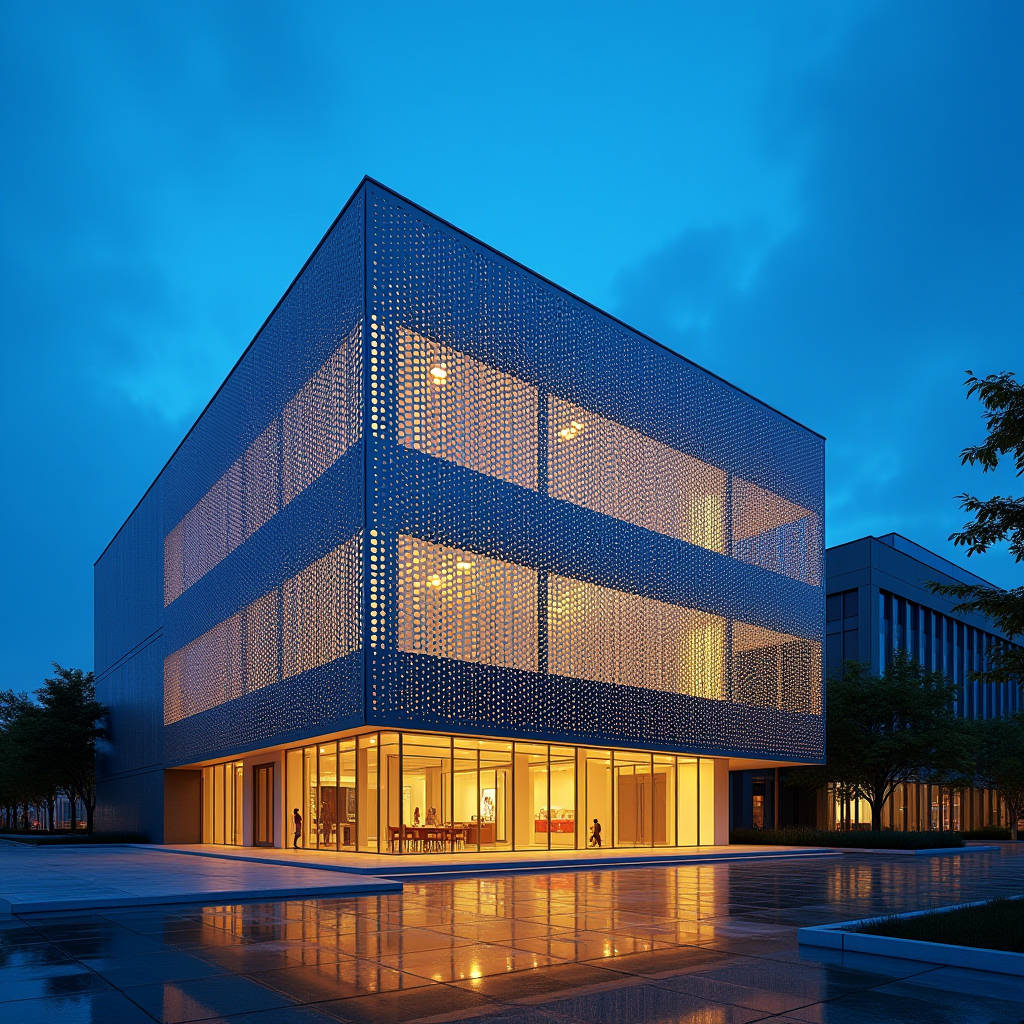
An illuminated aluminum facade represents one of the most technically demanding yet visually rewarding disciplines in modern building envelope engineering. When a project specification calls for perforated solid aluminum panels with integrated LED backlighting, the conversation shifts immediately from standard cladding to a multi-system interface where structural performance, optical diffusion, thermal management, and weatherproofing must coexist within a single assembly. Getting this right means understanding how a 2.5mm or 3.0mm solid aluminum sheet behaves after thousands of perforations are CNC-punched into it, how the PVDF coating withstands decades of UV exposure while allowing light to pass through cleanly, and how the LED array behind the panel is serviced without dismantling the entire facade. This article addresses the engineering decisions that determine whether an illuminated aluminum facade performs reliably across a 30-year building lifecycle or becomes a maintenance liability after the first warranty period.
Why Solid Aluminum Matters for Backlit Facade Applications
The substrate material behind every illuminated aluminum facade panel determines the long-term flatness, corrosion resistance, and perforation integrity of the entire system. Solid aluminum sheets — typically specified at 2.0mm, 2.5mm, or 3.0mm thickness from 3003-H14 or 5052-H32 alloy — offer a fundamentally different mechanical profile compared to composite alternatives. A 2.5mm solid aluminum panel maintains its dimensional stability even after 40% or more of its surface area has been removed through perforation. This matters because panel flatness directly affects the uniformity of backlit illumination. A panel that warps by even 3mm across a 1,200mm span creates visible hot spots and shadow lines that undermine the architectural intent.
The alloy selection itself carries weight here. 5052-H32 provides higher tensile strength (approximately 230 MPa) compared to 3003-H14 (around 150 MPa), making it the preferred choice for large-format illuminated panels exceeding 1,500mm in either dimension. The higher magnesium content in 5052 also improves corrosion resistance in coastal environments — a critical consideration when the perforations expose more raw edge surface to salt-laden air. For inland projects, 3003-H14 offers sufficient strength with better formability and lower material cost. Either way, the specification must call for a minimum 25μm PVDF coating on the visible face, applied via a three-coat system with a primer layer that bonds to the aluminum substrate and a clear topcoat that encapsulates the color layer. The reverse side — facing the LED cavity — typically receives a service coat of 10-15μm to prevent oxidation without the full aesthetic treatment.
Perforation Engineering and Light Transmission Physics
The relationship between perforation geometry and light output is not linear. An illuminated aluminum facade panel with 30% open area does not transmit 30% of the LED's luminous flux — the actual transmission depends on hole diameter, pitch, panel thickness, and the angle of light incidence. When LED modules are positioned 50-80mm behind the panel, the light cone expands before reaching the perforation plane. A 6mm diameter hole at 12mm staggered pitch (yielding approximately 22.6% open area) produces a markedly different visual effect than 3mm holes at 6mm pitch (same open area). The larger holes create distinct points of light at close viewing distances, while the smaller holes blend into a more homogeneous glow.
Panel thickness introduces another variable. A 3.0mm thick panel with 4mm diameter holes creates a noticeable "tunnel effect" where the hole walls partially occlude off-axis light. This can be exploited deliberately — panels viewed from below will appear dimmer than those viewed straight-on, creating a dynamic luminance shift as pedestrians move past the building. For projects requiring uniform brightness across all viewing angles, the hole diameter should be at least twice the panel thickness. This means 5mm minimum holes for 2.5mm panels, and 6mm minimum for 3.0mm panels.
Edge distance — the solid material remaining between the outermost perforations and the panel perimeter — must not drop below 2x material thickness. For a 2.5mm panel, that means 5mm minimum edge distance. In practice, most manufacturers maintain 10-15mm to accommodate the folding or welding of return edges. This solid border zone also provides the structural connection point for the substructure, where concentrated loads from wind pressure transfer through the panel to the mounting system.
LED Integration and Thermal Management Behind the Panel
The cavity behind an illuminated aluminum facade is a thermal environment that demands careful engineering. LED modules generate heat — typically 2-4 watts per linear foot for architectural-grade systems — and this heat must dissipate through the aluminum panel and the rear enclosure. When the cavity is sealed against moisture ingress, it can also trap solar radiation absorbed by the panel surface during daytime hours. Surface temperatures on a dark-colored PVDF-coated panel can reach 70°C in direct summer sun, and the LED components behind that panel must survive those conditions without degradation.
LED driver specification for illuminated aluminum facade installations should require an operating temperature range of -20°C to +60°C minimum, with thermal protection that automatically dims or shuts down output if internal temperatures exceed safe thresholds. The drivers themselves are best located in accessible service zones — not buried in the facade cavity — to allow replacement without panel removal. Some manufacturers, including Futeng®, recommend a ventilated rear plenum design where a 15-25mm air gap between the LED mounting plane and the weather barrier allows natural convection to carry heat upward and out through concealed vents at the top of each facade section.
Ingress protection ratings are non-negotiable. The LED modules and all wiring connections within the cavity must achieve IP65 minimum, with IP67 preferred for installations in coastal or high-rainfall regions. The panel-to-substructure connection points should incorporate EPDM gaskets that prevent water from migrating along fasteners into the LED cavity. Silicone sealants, while common in glazing applications, can outgas acetic acid during curing and corrode LED circuit boards — neutral-cure sealants are the correct specification here.
Structural Considerations for Perforated Panels Under Wind Load
Perforation reduces the wind-bearing surface area of a panel, which sounds beneficial until you consider that it also reduces the panel's structural stiffness. The remaining aluminum ligaments between holes must resist both positive and negative wind pressures while maintaining deflection within acceptable limits. ASTM E330 provides the standard test method for structural performance of exterior windows, doors, and curtain walls under uniform static air pressure difference, and this standard applies directly to illuminated aluminum facade panels.
A practical approach to deflection analysis involves calculating the effective section modulus of the perforated panel. For a solid 2.5mm aluminum sheet spanning 600mm between supports, the section modulus is straightforward. Once perforated with 6mm holes at 12mm staggered pitch, the effective section modulus drops by approximately 28-35%, depending on the specific pattern. This reduction must be factored into the structural calculation, and the supporting subframe spacing may need to decrease from 600mm to 450mm or even 400mm to maintain deflection under L/175 or L/240 limits.
The subframe itself — typically extruded aluminum T-profiles or hat channels — must accommodate differential thermal movement between the illuminated panel and the building structure. A 3-meter tall panel in dark bronze PVDF can expand by 4-5mm between winter and summer temperature extremes. The mounting clips must allow this movement without transferring stress to the LED modules or compromising the weather seal. Stainless steel clip systems with slotted connections are standard practice, with 304-grade stainless specified for inland applications and 316-grade for coastal or industrial environments.
Coating Performance and Light Reflectance
The interior surface of an illuminated aluminum facade panel — the side facing the LEDs — plays an active role in light distribution. A standard PVDF service coat on the reverse side has a reflectance of approximately 40-60%, depending on color and gloss level. For maximum light output through the perforations, the reverse side should be specified in white or light gray with a reflectance above 70%. This turns the panel interior into a secondary reflector that bounces stray photons back toward the perforations rather than absorbing them into the aluminum substrate.
The exterior PVDF coating requires a different set of priorities. Color retention under UV exposure is governed by the pigment chemistry and the quality of the clear topcoat. Kynar 500® or Hylar 5000® resin-based PVDF coatings with a minimum 70% resin content by weight provide the benchmark for architectural aluminum. AAMA 2605 sets the performance standard: no more than 5 Delta E color change after 10 years of South Florida exposure. For illuminated panels, this matters doubly because any color shift or chalking on the panel face becomes dramatically visible when backlit — the light passing through perforations creates a contrast that highlights surface imperfections.
The table below compares coating specifications relevant to illuminated aluminum facade panels across different environmental conditions:
| Coating Parameter | Standard Interior | Urban Exterior | Coastal Exterior | Industrial Exterior |
|---|---|---|---|---|
| Resin System | Polyester | PVDF (70% resin) | PVDF (70% resin) | PVDF (70% resin) |
| Total DFT (Face) | 25-30μm | 30-35μm | 35-40μm | 35-40μm |
| Primer Layer | 5-8μm | 5-8μm | 8-10μm | 8-10μm |
| Clear Topcoat | Optional | 12-15μm | 15-18μm | 15-18μm |
| Reverse Side DFT | 10-15μm | 10-15μm | 15-20μm | 15-20μm |
| Salt Spray Resistance | N/A | 1,000 hrs | 3,000 hrs | 1,500 hrs |
| Expected Service Life | 10-15 years | 20-25 years | 15-20 years | 15-20 years |
Serviceability: The Often-Overlooked Design Constraint
LED modules have a rated lifespan — typically 50,000 to 100,000 hours at L70 (the point where light output drops to 70% of initial levels). This translates to 11 to 22 years at 12 hours of nightly operation. The aluminum facade panels themselves, properly coated and maintained, can last 30 to 50 years. This fundamental mismatch means that every illuminated aluminum facade must be designed for LED replacement without destroying the cladding system.
Three access strategies dominate the industry. The first uses individually removable panels where each illuminated unit is mounted on a hinged or clipped frame that can be swung open or lifted out from the front. This approach provides the best access but introduces visible joint lines and potential alignment issues. The second strategy places the LED modules on a separate rear-mounted rail system accessible from inside the building envelope — ideal for new construction where the facade cavity is designed with maintenance walkways. The third approach, common in double-skin facades, positions the LEDs in the intermediate cavity where technicians can access them from dedicated service levels.
The panel attachment method must be specified with serviceability in mind. Concealed clip systems that require panel deformation for removal are inappropriate for illuminated panels — the risk of bending the panel and disrupting the perforation pattern or damaging the coating is too high. Exposed mechanical fasteners with color-matched heads, while visually less clean, allow straightforward panel removal. For projects where visible fasteners are unacceptable, a cassette system with side-accessible locking tabs provides a compromise between aesthetics and maintainability.
Control Systems and Dynamic Facade Programming
An illuminated aluminum facade reaches its full potential when paired with a DMX or DALI control protocol that allows individual panel or zone-level addressing. DMX512 — originally developed for stage lighting — has become the de facto standard for architectural facade lighting due to its robust daisy-chain topology and support for up to 512 channels per universe. Each RGBW LED module behind a perforated panel requires four channels (red, green, blue, white), meaning a single DMX universe can control 128 individual RGBW panel units.
DALI (Digital Addressable Lighting Interface) offers an alternative with bidirectional communication — each driver reports its status back to the control system, enabling automated fault detection across hundreds of facade panels. For large-scale illuminated aluminum facade installations exceeding 500 panels, a hybrid approach often works best: DALI for individual driver control and monitoring, with a DALI-to-DMX gateway for the synchronized color-changing sequences visible from the street.
The control cabinet placement requires coordination with the facade engineering team. Each LED driver typically serves 4-8 linear meters of LED strip, and the voltage drop across low-voltage DC wiring (commonly 24V) limits the distance between driver and LED module to approximately 10-15 meters before noticeable brightness degradation occurs. This constraint often dictates that driver cabinets be distributed across multiple floors rather than centralized in a single basement location.
Weatherproofing the Illuminated Cavity
Water management behind an illuminated aluminum facade follows the rainscreen principle but with additional complexity. The perforated panel itself is not watertight — rain will pass through the holes and enter the cavity. This is acceptable only if the cavity is designed as a drained and ventilated zone with a continuous water-resistive barrier (WRB) behind the LED mounting plane. The WRB must be protected from UV exposure that could degrade it over time, which the aluminum panel and LED mounting plane naturally provide.
Drainage paths at the base of each cavity section must be sized to handle the water volume entering through the perforations during a design storm event. A 25mm x 3mm continuous slot drain at the bottom of each 1,200mm wide panel bay can typically handle the water from a 100mm/hour rainfall rate, but this must be verified through calculation based on the specific open area of the perforation pattern. Weep holes should be spaced no more than 600mm apart and must incorporate insect screens to prevent nesting in the cavity.
Condensation presents another challenge. When warm, humid exterior air contacts the cooler aluminum panel surface during nighttime operation — particularly when the LEDs are off and the panel has cooled — moisture can condense on the interior panel face and drip onto the LED modules. A hydrophobic coating on the panel interior, combined with a slight slope (minimum 2 degrees) toward the drainage plane, mitigates this risk. Some manufacturers, including Futeng®, apply a clear anti-condensation treatment to the reverse side of panels destined for humid climates.
Cost Drivers and Value Engineering
The premium for an illuminated aluminum facade over standard solid aluminum cladding ranges from 60% to 150%, depending on perforation complexity, LED specification, and control system sophistication. Breaking this down: perforated panel fabrication adds approximately 30-50% to the base panel cost, LED modules and drivers contribute 20-35%, the modified substructure accounts for 10-15%, and the control system adds 15-25%. The remaining variance comes from access strategy, site logistics, and commissioning complexity.
Value engineering efforts should focus on areas that do not compromise long-term performance. Reducing panel thickness from 3.0mm to 2.5mm can save 15-20% on material cost but must be validated structurally. Standardizing perforation patterns across the project reduces CNC programming and tooling charges. Selecting a single LED color temperature (rather than RGBW) for non-dynamic applications cuts control system costs by approximately 40%. What should not be compromised: PVDF coating quality, structural subframe design, weatherproofing details, and service access provisions. These elements determine whether the illuminated aluminum facade remains a building asset or becomes a liability.
For procurement managers evaluating supplier capabilities, the key differentiators are in-house CNC perforation capacity, PVDF coating line certification to AAMA 2605, and a documented track record of integrated facade-lighting projects. The ability to provide a single-source warranty covering both the aluminum panels and the integrated LED system — rather than separate warranties from a panel fabricator and a lighting contractor — significantly reduces the risk of finger-pointing when issues arise during the service life.
Engineering an illuminated aluminum facade demands coordination across disciplines that typically operate in silos: facade engineering, electrical engineering, lighting design, and building physics. The projects that succeed are those where the aluminum panel manufacturer participates in design development meetings alongside the lighting consultant and the facade contractor, rather than receiving a finished specification to price. The perforation pattern, panel thickness, coating specification, LED selection, and access strategy are interdependent variables that cannot be optimized in isolation. When these decisions are made collaboratively and documented in a comprehensive interface matrix, the resulting illuminated aluminum facade delivers the visual impact that architects seek while meeting the durability and maintainability standards that building owners require.