Kinetic Aluminium Facade Engineering What Procurement Teams Must Know About Panel Fatigue and Alloy Selection
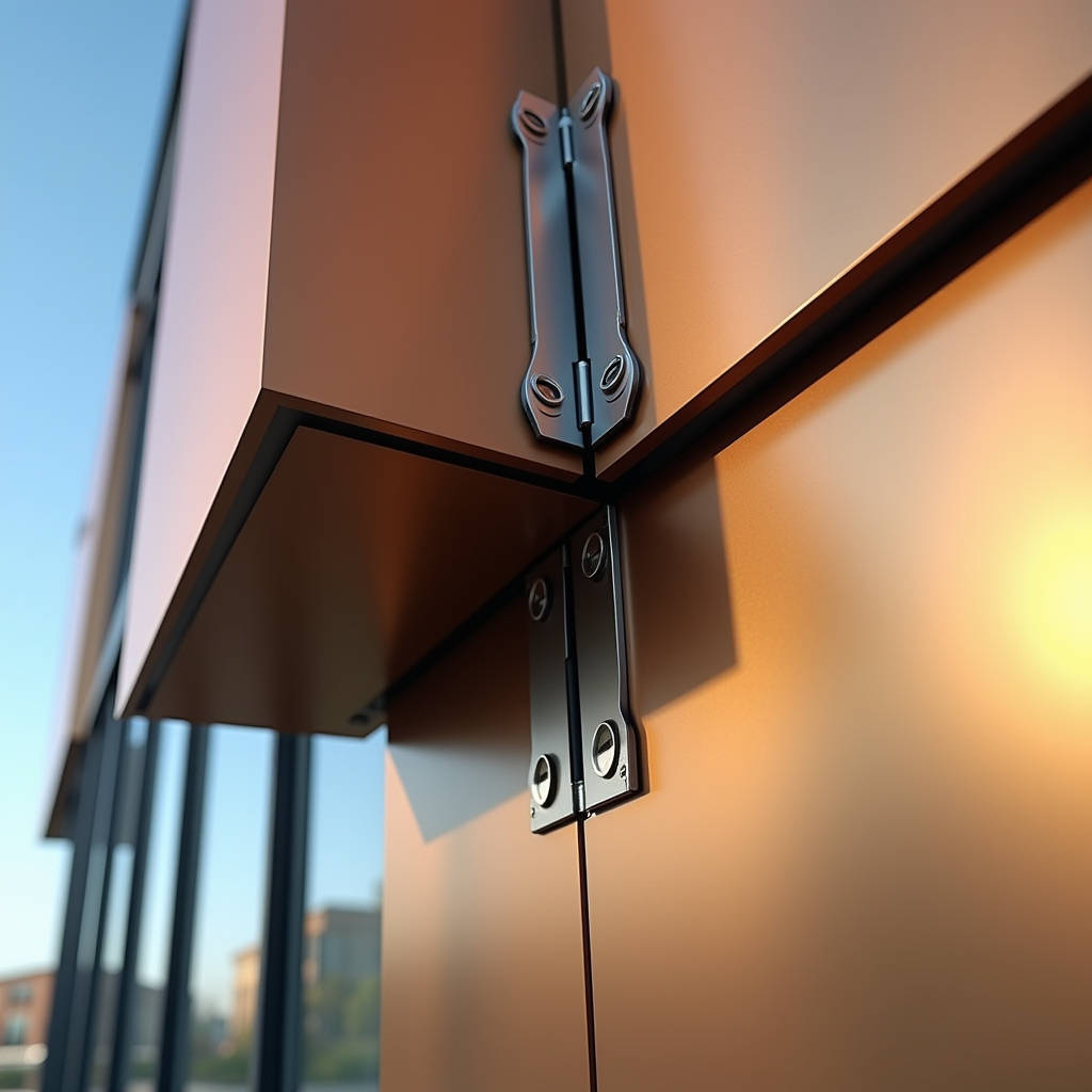
When a facade moves, every connection point becomes a potential failure node. This is the engineering reality that separates a functioning Kinetic Aluminium Facade from an expensive liability. Architects chasing parametric expression and building owners demanding energy-responsive envelopes have pushed kinetic systems from experimental pavilions into commercial towers, parking structures, and institutional buildings. But the procurement teams and facade contractors responsible for delivering these systems face a harder question: what happens to solid aluminium panels when they stop being static cladding and start articulating thousands of times per year under wind, thermal, and mechanical loads?
The shift from static rainscreen to dynamic envelope changes the entire engineering calculus. Panel thickness, alloy selection, coating durability, and fixing design all require re-evaluation when the cladding moves. A 2.5mm solid aluminium panel performing flawlessly on a fixed facade for 30 years might develop stress fractures at its anchor points within five years on a poorly designed kinetic system. This article examines the specific material and engineering considerations that procurement teams must address when specifying solid aluminium panels for a Kinetic Aluminium Facade — focusing on the intersection of alloy grade, panel thickness, coating technology, and long-term fatigue performance.
Why Movement Changes Everything for Solid Aluminium Panels
Static aluminium cladding has one job: hang there and resist wind load. The engineering is mature. AAMA 508, ASTM B209, and EN 485 provide clear pathways for alloy selection, thickness calculation, and fixing design. A 2.0mm or 2.5mm panel on a conventional rainscreen system experiences predominantly static loads with occasional dynamic peaks during storms. The aluminium stays well within its elastic deformation range, and fatigue is rarely a design-governing factor.
A Kinetic Aluminium Facade flips this assumption. Panels that rotate, slide, fold, or pivot introduce cyclic loading at every connection point. A facade louver that opens and closes 20 times daily based on solar tracking will cycle over 7,000 times per year. Over a 20-year design life, that is 140,000 cycles. For a wind-responsive flap system on a parking structure — similar to the KINETICWALL concept — the cycle count could be far higher in coastal or high-wind locations.
At 140,000 cycles, aluminium alloy selection becomes critical. The fatigue strength (endurance limit) of 3003-H14 alloy at 5×10⁸ cycles is approximately 69 MPa. For 5052-H32, it rises to roughly 110 MPa. For 6061-T6, it reaches approximately 97 MPa. These numbers are not academic — they directly determine whether a panel's anchor tabs will crack in year 7 or survive to year 30. The procurement specification must explicitly state the required alloy and temper, not simply "aluminium panel."
Alloy Selection: The Foundation of Kinetic Durability
Not all 3xxx and 5xxx series alloys behave the same way under cyclic stress. The three alloys most commonly encountered in solid aluminium cladding — 3003, 5052, and 6061 — present distinct trade-offs between formability, corrosion resistance, and fatigue performance that procurement teams must understand before issuing a tender package.
3003-H14 offers excellent formability and is widely available. It bends easily into complex geometries, which makes it attractive for kinetic panels with folded edges or curved profiles. However, its lower fatigue strength means it is better suited to low-cycle applications — perhaps a manually adjustable shading fin that moves twice daily rather than a continuously wind-driven element. For a high-cycle Kinetic Aluminium Facade, 3003 requires thicker gauge material to compensate, adding weight that the actuation system must overcome.
5052-H32 provides the best balance for most kinetic applications. Its magnesium content (2.2-2.8%) delivers higher tensile strength (210-260 MPa) and superior fatigue resistance compared to 3003, while maintaining good corrosion resistance in marine and industrial environments. For coastal projects where salt spray combines with mechanical cycling, 5052 is the conservative choice. The trade-off is slightly reduced formability — tight-radius bends may require stress-relief annealing at the bend line, which adds a processing step.
6061-T6 offers the highest strength but presents fabrication challenges. Its elongation is lower (8-10% vs. 12-18% for 5052-H32), meaning it cracks more readily during forming. For kinetic panels requiring complex shapes, 6061-T6 typically demands CNC machining rather than press braking, driving up fabrication costs. It is best reserved for structural elements within the kinetic assembly — mounting brackets, pivot arms, and actuator connection plates — rather than the visible facade panels themselves.
Panel Thickness: Beyond the 2.0mm Default
The solid aluminium cladding industry has standardised around 2.0mm, 2.5mm, and 3.0mm thicknesses for static applications. Wind load span tables from manufacturers typically assume a simply supported panel with uniform pressure. On a kinetic system, the panel also experiences concentrated loads at hinge points, torsion along pivot axes, and potential impact when panels close against stops.
For a rotating panel measuring 1200mm × 600mm on a Kinetic Aluminium Facade, moving from 2.0mm to 2.5mm thickness increases the section modulus by approximately 56%, dramatically improving resistance to the torsional deflection that occurs when one edge of the panel is driven while the opposite edge lags due to inertia. The weight penalty — roughly 1.35 kg/m² per additional 0.5mm — must be factored into actuator sizing and structural support design. This is not a simple "thicker is better" decision; it is an optimisation problem that the facade engineer must solve with accurate material data.
Procurement teams should request from panel suppliers — such as Futeng®, which manufactures solid aluminium panels in 2.0mm to 3.0mm gauges with PVDF coating systems — detailed mill certificates showing actual gauge tolerance, not just nominal thickness. The EN 485-3 standard permits a tolerance of ±0.08mm on 2.0mm sheet. A panel delivered at 1.92mm instead of 2.0mm loses approximately 12% of its bending stiffness. On a kinetic system, that variance can shift natural frequencies enough to cause unexpected resonance under certain wind speeds.
Coating Systems Under Cyclic Strain
PVDF (polyvinylidene fluoride) coatings dominate the architectural aluminium market for good reason. A properly applied 70% PVDF system with 30-35 microns dry film thickness delivers 20+ years of colour stability and chalk resistance under ASTM D4214 testing. But these tests assume a static substrate. On a kinetic panel, the coating experiences repeated micro-strain every time the panel moves.
The strain compatibility of the coating system becomes a performance factor. PVDF coatings are relatively flexible compared to polyester or epoxy systems, which is why they survive roll-forming and bending operations. However, repeated strain at the same location — such as the edge of a hinge bracket where the panel flexes — can initiate micro-cracking in the coating over thousands of cycles. Once moisture penetrates through micro-cracks to the aluminium substrate, filiform corrosion can propagate beneath the coating, invisible until it emerges as blistering at the panel edge.
The following table provides a comparative reference for coating performance parameters relevant to kinetic applications:
| Coating Parameter | 70% PVDF (Spray) | FEVE (Spray) | Powder Coating (PE) | Relevance to Kinetic Facade |
|---|---|---|---|---|
| Dry Film Thickness | 30-35 µm | 30-40 µm | 60-80 µm | Thicker powder coats may crack earlier under cyclic strain |
| Elongation at Break | 20-50% | 10-30% | 5-15% | Higher elongation = better strain compatibility with moving substrate |
| Pencil Hardness | HB-F | F-H | H-2H | Harder coatings are more brittle; kinetic panels benefit from flexibility |
| AAMA 2605 Compliance | Yes | Yes | No (AAMA 2604 max) | 2605-grade required for exterior kinetic elements with UV exposure |
| Accelerated Weathering (QUV 5000h) | Delta E < 5 | Delta E < 5 | Delta E < 8 | Kinetic panels cannot be easily recoated; colour stability is critical |
| Typical Cost Index (per m²) | 100% (baseline) | 110-125% | 60-75% | Budget allocation must account for lifecycle, not just upfront cost |
For a Kinetic Aluminium Facade, the specification should mandate AAMA 2605-compliant PVDF or FEVE coatings with a minimum elongation of 20%, tested per ASTM D522 (conical mandrel) on the actual aluminium alloy and gauge specified — not on a generic test panel. The coating supplier should provide cyclic strain test data if available, or at minimum confirm that the system has been used on roll-formed or bent components without cracking.
Fixing Design: Where Theory Meets Fatigue Failure
The fixing system on a kinetic facade is fundamentally different from a static rainscreen. Static panels use rivets, screws, or cassette clips that experience predominantly shear loads from panel weight and tension from wind suction. The design approach is straightforward: calculate the worst-case load, apply a safety factor (typically 3.0 for aluminium per AAMA TIR-A9), and select a fastener with adequate capacity.
On a kinetic system, the fasteners at hinge points and actuator connections experience fully reversed or fluctuating stress cycles. A bolt that connects a rotating panel to its pivot arm might see tension during one phase of movement and compression during another. The stress ratio (R = minimum stress / maximum stress) can be zero or even negative. Under these conditions, the allowable stress from a static analysis is irrelevant — the design must be governed by the fatigue limit of the fastener material and the aluminium at the connection.
Several practical measures reduce the risk of fatigue failure at connections on a Kinetic Aluminium Facade:
- Bushings at pivot points. Stainless steel bushings pressed into aluminium hinge holes prevent the steel bolt from fretting directly against the softer aluminium, which would otherwise initiate cracks at the hole edge within a few thousand cycles.
- Oversized washers or backing plates. Distributing the cyclic load over a larger bearing area reduces the local stress concentration. A 3mm-thick aluminium backing plate behind the panel at each connection point can double the fatigue life compared to a standard washer.
- Threaded inserts rather than self-tapping screws. Self-tapping screws cut threads into the aluminium, creating sharp stress risers. Threaded inserts (heli-coil or key-locking type) installed in the panel provide a fatigue-resistant interface. This is standard practice in aerospace aluminium structures and should be adopted for high-cycle kinetic facades.
- Periodic inspection access. Unlike a static facade where fixings are hidden and forgotten, kinetic systems require access for inspection. The design should include removable access panels or end caps that allow a technician to inspect hinge connections and actuator mounts without dismantling the entire assembly.
Actuator Integration and Panel Flatness
Solid aluminium panels are flat. That sounds obvious, but it has consequences for kinetic systems. When a linear actuator pushes or pulls on a flat panel, any misalignment between the actuator's line of action and the panel's stiffest axis introduces bending moments that the panel was not designed to resist. Over time, this manifests as a permanent set — the panel develops a visible bow or twist that ruins the crisp aesthetic that kinetic facades are meant to deliver.
The panel's flatness tolerance, typically specified as 0.2% of the diagonal dimension per EN 485-3, becomes a quality control parameter with direct functional impact. A panel that is within flatness tolerance but near the upper limit may behave differently under actuator loading than one at the nominal flatness. For large kinetic panels exceeding 2m², procurement specifications should tighten the flatness requirement to 0.15% of diagonal and require the supplier to verify flatness after all fabrication operations — routing, folding, and insert installation — not just on the raw sheet.
Actuator mounting points on the panel should be reinforced with bonded stiffeners. A 2.5mm aluminium stiffener plate, structurally bonded to the rear of the panel with a high-modulus structural adhesive (such as a two-part epoxy with a lap shear strength exceeding 15 MPa per ASTM D1002), distributes the actuator force and prevents localised dimpling of the visible surface. This is a detail that separates a facade that looks precise after installation from one that develops visible distortion within the first year of operation.
Wind Response: The Control Logic Problem
A Kinetic Aluminium Facade that responds to wind — such as the wave-generating systems seen on parking structures — presents a control challenge that directly affects panel specification. When wind speed exceeds the design threshold, the control system must decide whether to move panels to a "safe" position (typically fully open or fully closed) or to lock them in place. The wrong decision can expose panels to loads they were not designed to withstand.
If panels are left in a partially open position during a wind gust, the aerodynamic loading is fundamentally different from the uniform pressure assumed in static design. A panel angled at 45 degrees to the wind experiences a combination of lift and drag forces that can produce a net pressure coefficient (Cp) significantly higher than the 1.0-1.5 typically used for wall cladding. The ASCE 7 standard provides pressure coefficients for various configurations, but the specific geometry of a kinetic louver array may require wind tunnel testing to characterise accurately.
The procurement specification should require the control system supplier to define the "safe mode" position and the wind speed at which it is triggered. The panel supplier then needs this information to verify that the panels, fixings, and actuator connections can withstand the safe-mode loads, including any dynamic amplification from gusts. This is a coordination item that frequently falls through the cracks between the facade contractor, the actuator supplier, and the panel manufacturer — with the panel manufacturer often receiving incomplete load data.
Thermal Expansion in Moving Assemblies
Aluminium expands at approximately 23 × 10⁻⁶ per °C. A 3-metre panel on a static facade experiences a length change of about 4.8mm across an 80°C temperature range. Standard rainscreen detailing accommodates this with slotted holes and expansion gaps. On a kinetic system, thermal movement compounds with mechanical movement. The hinge axis that was perfectly aligned at 20°C may bind at 70°C if the differential expansion between the aluminium panel and the steel support structure has not been accounted for.
The solution is to design the kinetic assembly with one fixed pivot and one floating pivot. The fixed pivot constrains the panel in all three translational axes. The floating pivot allows axial movement along the hinge line to accommodate thermal expansion. This requires a sliding bearing — typically a bronze or PTFE-lined bushing — at the floating end. The specification for the bushing material must consider not just the mechanical wear from thousands of cycles but also the potential for galvanic corrosion between the bushing, the aluminium panel, and the stainless steel pin in the presence of moisture.
Quality Assurance: Testing Beyond the Static Standard
Standard QA for solid aluminium cladding panels focuses on dimensional accuracy, coating performance, and static load testing. For a Kinetic Aluminium Facade, the QA regimen must expand to include dynamic testing that simulates the actual service conditions. This does not mean testing every panel — that would be impractical — but it does mean testing a representative assembly before production begins.
A meaningful dynamic test protocol for kinetic panels includes:
- Cycle testing of the full assembly. A minimum of 50,000 cycles at the design movement range and speed, with inspection for cracking, loosening, and coating damage at 10,000-cycle intervals.
- Strain gauge measurement at connection points. During the first 1,000 cycles, strain gauges at hinge holes and actuator mounts confirm that actual stresses align with the design assumptions. If measured strains exceed 50% of the material's fatigue limit, the design requires revision.
- Coating adhesion testing after cycling. ASTM D3359 cross-hatch adhesion testing performed on the cycled panel, specifically at areas of maximum curvature or flexure, to verify that the coating system has not delaminated.
- Salt spray exposure after cycling. ASTM B117 testing for 1,000 hours on a cycled panel to confirm that micro-cracks in the coating have not opened pathways for corrosion. This is particularly relevant for coastal projects.
These tests add cost and time to the procurement schedule — typically 8-12 weeks for fabrication and testing of a prototype assembly. But the alternative is discovering a systemic fatigue problem after 500 panels have been installed on a 20-storey building. The cost of access equipment alone for replacing failed panels at height can exceed the entire testing budget by an order of magnitude.
Procurement Strategy: Specifying for Kinetic Applications
Procurement managers writing tender documents for a Kinetic Aluminium Facade should treat the panel specification as distinct from a standard cladding package. The following points should be explicitly addressed in the inquiry documents:
- Alloy and temper. State the required alloy (e.g., 5052-H32) and reference the applicable standard (ASTM B209 or EN 485). Do not accept "aluminium sheet" as a description.
- Gauge tolerance. Specify the minimum acceptable thickness, not just the nominal. For a 2.5mm panel, require that no point on the panel measures less than 2.42mm.
- Coating system and strain compatibility. Require AAMA 2605-compliant PVDF or FEVE with documented elongation data. Request evidence of the coating's performance on formed or flexed aluminium components.
- Fixing and reinforcement details. Require shop drawings showing all hinge reinforcements, bushing materials, and backing plates. These should be reviewed by the facade engineer, not just the architect.
- Dynamic testing requirements. Define the cycle count, inspection intervals, and acceptance criteria for prototype testing. Reference relevant standards where possible — while no single standard covers kinetic facade panels, elements of ASTM E330 (structural performance) and AAMA 501.4 (dynamic wind testing) can be adapted.
- Supplier qualifications. Require evidence of previous kinetic or dynamic facade projects. A supplier with extensive static cladding experience but no dynamic experience may underestimate the engineering challenges.
Manufacturers such as Futeng®, with production capability for solid aluminium panels in 2.0mm to 3.0mm gauges and AAMA 2605-compliant PVDF coating lines, can meet these requirements when the specification is clearly communicated. The key is that the specification must be kinetic-specific from the outset — retrofitting kinetic requirements onto a standard cladding spec during the submittal phase leads to cost overruns, schedule delays, and compromised performance.
Cost Realities: What Kinetic Adds to the Panel Budget
There is no avoiding the fact that panels for a kinetic facade cost more than equivalent static panels. The cost premium comes from several sources: higher-grade alloy, tighter thickness tolerance, additional reinforcement stiffeners, threaded inserts instead of simple drilled holes, and more extensive QA documentation. Based on project experience, the panel cost premium for kinetic applications typically ranges from 25% to 45% over standard solid aluminium cladding panels of the same dimensions.
However, this premium must be weighed against the total facade cost. The panels themselves represent perhaps 30-40% of the total kinetic facade budget, with the remainder going to actuators, control systems, support structure, wiring, and installation. A 35% increase in panel cost translates to roughly a 10-14% increase in total facade cost — a meaningful but manageable increment that buys a dramatic reduction in long-term failure risk.
The more expensive mistake is specifying standard static panels for a dynamic application and absorbing the cost of premature failures. Replacing failed panels on a kinetic facade typically costs 5-10 times the original panel cost when access, labour, and disruption are factored in. The engineering investment in proper panel specification pays for itself many times over across the building's service life.
The Kinetic Aluminium Facade represents a genuine advance in building envelope performance — combining energy management, occupant comfort, and architectural expression in ways that static facades cannot match. But the engineering demands on the aluminium panels at the heart of these systems are fundamentally different from conventional cladding. Procurement teams that recognise this difference and specify accordingly will deliver facades that move reliably for decades. Those that treat kinetic panels as standard cladding with hinges attached will learn expensive lessons in fatigue, corrosion, and coating failure. The choice is made at the specification stage, long before the first panel is fabricated.