Kinetic Aluminum Facade Engineering Wind Loads Material Specs and Lifecycle Costs
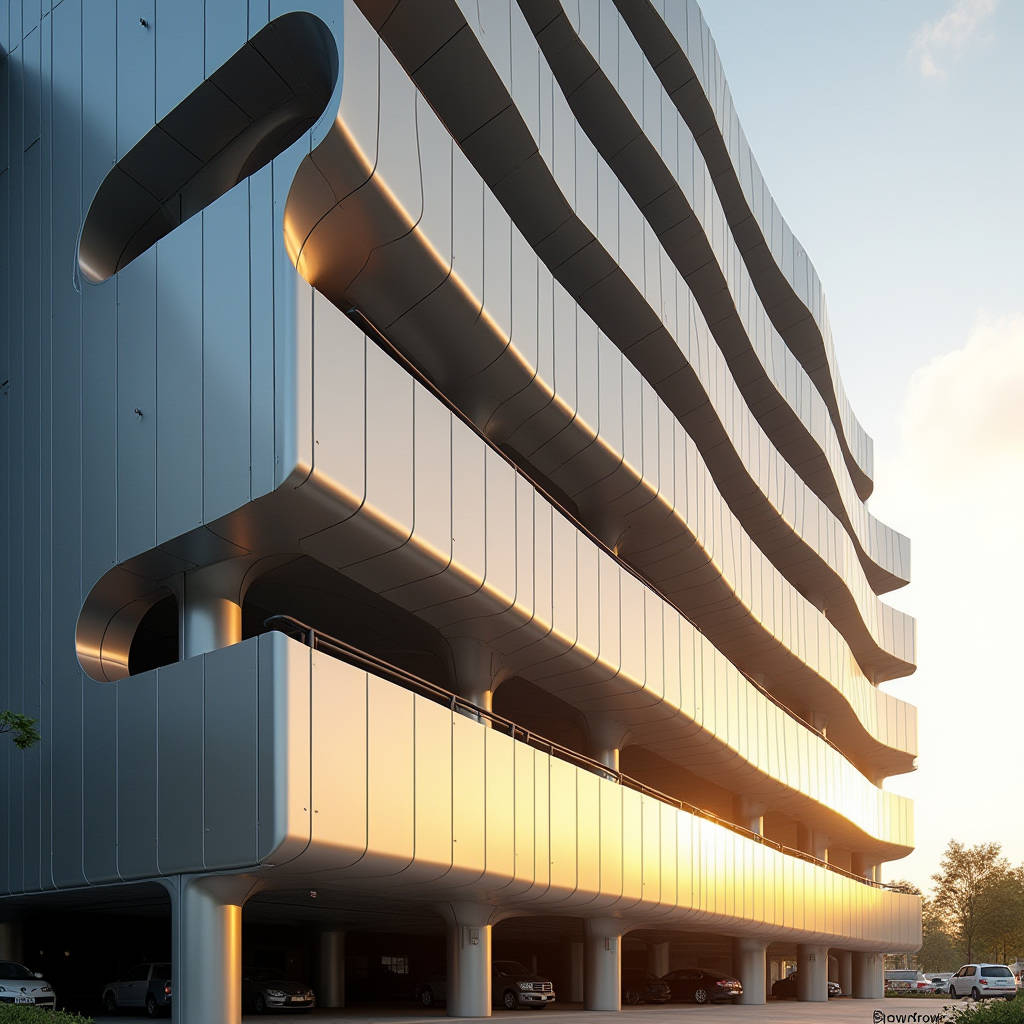
Wind doesn't just hit a building. It pushes, pulls, twists, and over time, it wears things down. A Kinetic Aluminum Facade turns that constant pressure into something useful. Instead of fighting the wind, the facade moves with it. Small aluminum panels, each mounted on a pivot, catch the breeze and shift position. The result is a building skin that breathes, reduces structural load, and creates a surface that never looks the same twice. This isn't decoration. It's a mechanical strategy that solves real problems: solar heat gain, ventilation in semi-open spaces, and the fatigue that comes from wind buffeting on large flat surfaces. For contractors and facade engineers, the question isn't whether kinetic systems work. It's how to specify them without creating a maintenance nightmare, how to calculate wind loads when the cladding itself is moving, and where solid aluminum panels outperform other materials in these dynamic assemblies.
How a Kinetic Aluminum Facade Actually Works
The principle is straightforward. Individual aluminum panels are mounted on horizontal or vertical axles, connected by a linkage system that synchronizes movement across the entire facade. Wind pressure on one panel transfers through the linkage to its neighbors. A gust that hits the bottom-left corner of a building will ripple across the surface in a wave pattern, with each panel tilting a few degrees before returning to its neutral position.
The panels themselves are typically 2.0mm to 3.0mm solid aluminum sheets, fabricated to precise dimensions with folded returns on all four edges. Weight matters here. A panel that's too heavy won't respond to light breezes. Too light, and it flutters uncontrollably. At 2.5mm thickness, a standard 600mm x 600mm solid aluminum panel weighs roughly 2.4 kg — enough mass to resist flutter, light enough to move in a 15 km/h wind.
The linkage mechanism deserves attention. Most systems use stainless steel rods with ball joints at each panel connection point. These joints need to handle thousands of movement cycles per day without developing play or seizing up. A typical kinetic facade on a mid-rise building in a coastal city might see 3 to 5 million movement cycles per year. Bearing selection and corrosion protection on every moving part determine whether the system still operates smoothly after five years or becomes a static — and expensive — fixed cladding system.
Wind Load Calculations When the Facade Moves
Standard wind load calculations assume a static surface. ASCE 7-16 and EN 1991-1-4 provide pressure coefficients for rectangular buildings with fixed cladding. A Kinetic Aluminum Facade breaks those assumptions. When panels tilt open, the effective wind-bearing area changes. When they close, pressure can spike locally before the linkage redistributes the load.
Engineers working on these systems typically run computational fluid dynamics (CFD) simulations for at least three panel positions: fully closed, 45-degree open, and fully open at 90 degrees. The worst-case pressure scenario often occurs not at full closure but at partial opening, where airflow constriction between panels creates localized high-pressure zones. For a 20-story building with a kinetic facade on the prevailing wind face, peak negative pressure at panel edges can reach 1.8 times the values predicted by static cladding calculations.
The linkage system itself introduces load paths that don't exist in conventional cladding. Wind force on one panel travels through the connecting rod to adjacent panels and ultimately to the structural anchors at panel group boundaries. A typical panel group might span 3 meters wide by 6 meters tall, with fixed anchor points at the four corners of each group. The rods between panels act as tension-compression members, and they need to be sized for the cumulative wind load across all panels in the group, not just the load on a single panel.
For specification purposes, the aluminum panels themselves should meet the requirements of ASTM B209 for aluminum sheet and plate. The PVDF coating system — typically a three-coat or four-coat system with a minimum 30-micron total dry film thickness — should conform to AAMA 2605. These aren't optional upgrades. On a moving facade, coating integrity matters more than on static cladding because any crack or scratch becomes a corrosion initiation point that sees repeated stress cycling.
Material Selection: Why Solid Aluminum Panels Fit Kinetic Systems
Kinetic facades place demands on cladding materials that static applications don't. Each panel experiences cyclic loading at its connection points. The folded returns where the pivot mechanism attaches become stress concentration zones. Materials with low fatigue resistance develop cracks at these points, usually within the first two years of operation.
Solid aluminum in the 3003-H14 or 5052-H32 temper offers a combination of properties that suits kinetic applications. The 5052 alloy, with magnesium as the primary alloying element, provides higher fatigue strength than the 3003 series — roughly 110 MPa versus 70 MPa in the fully reversed bending fatigue test at 500 million cycles. For a kinetic facade expected to operate for 20-plus years, that difference matters. The 5052 alloy also handles the repeated bending stress at folded panel edges better than most alternatives.
Panel thickness selection follows a logic that differs from static cladding. Static panels are often specified at 2.0mm for cost savings, with 2.5mm for larger spans. Kinetic panels almost always require 2.5mm minimum, and 3.0mm is common for panels larger than 900mm in any dimension. The extra thickness isn't about wind load capacity — it's about stiffness at the connection points and resistance to the subtle deformation that accumulates over millions of cycles.
Fabrication tolerances tighten considerably for kinetic systems. A static panel with a ±1.5mm dimensional variation still installs without issues. The same variation on a kinetic panel means the pivot points don't align, the linkage binds, and the entire panel group moves unevenly or not at all. Panel fabricators supplying kinetic projects need to hold ±0.5mm on critical dimensions, particularly the hole positions for pivot bearings and the flatness across the panel face. This level of precision requires CNC punching and folding equipment, not manual fabrication methods.
Coating Systems and Durability on Moving Surfaces
PVDF coatings dominate the architectural aluminum market for good reason. A properly applied three-coat system — primer, color coat, and clear topcoat — delivers 20-plus years of color stability and chalk resistance in static applications. On a kinetic facade, the coating faces additional challenges: abrasion where panels contact each other during movement, flexing that stresses the coating-to-metal bond, and exposure to whatever airborne particles pass between the open panels.
The four-coat PVDF system adds a barrier primer beneath the standard primer layer, specifically formulated to prevent corrosion at cut edges and drilled holes. On kinetic panels, every pivot connection point involves a drilled hole through the panel return. Without a barrier primer, moisture wicks into the aluminum at these holes, and the repeated stress of panel movement accelerates the corrosion process. The four-coat system adds roughly 15-20% to the coating cost but extends the functional life of kinetic panels by an estimated 5-8 years based on accelerated weathering tests per ASTM G154.
An alternative worth considering for kinetic applications is the FEVE (fluoroethylene vinyl ether) resin-based coating system. FEVE coatings offer similar weatherability to PVDF but with higher gloss retention and better flexibility. The flexibility advantage matters on kinetic panels because the coating can stretch slightly as the panel flexes under wind load, reducing micro-cracking. FEVE systems are less common in North America than in Asia and Europe, but their adoption is growing for dynamic facade applications.
| Coating System | Dry Film Thickness | Flexibility (Mandrel Bend) | Accelerated Weathering | Relative Cost | Best Application |
|---|---|---|---|---|---|
| 3-Coat PVDF (AAMA 2605) | 30-35 μm | 2T - No Crack | 4,000 hrs QUV-B | 1.0x (Baseline) | Standard kinetic, inland |
| 4-Coat PVDF (AAMA 2605) | 40-45 μm | 2T - No Crack | 5,000+ hrs QUV-B | 1.15-1.20x | Coastal, high-humidity kinetic |
| FEVE (3-Coat) | 30-35 μm | 1T - No Crack | 4,000 hrs QUV-B | 1.25-1.35x | High-movement, high-gloss |
| Anodized (AA-M12C22A31) | 15-20 μm (AA15-AA20) | Brittle - Cracks at 3T | N/A (Color fade issues) | 0.70-0.85x | Not recommended for kinetic |
| Powder Coating (AAMA 2604) | 60-80 μm | 3T - No Crack | 1,500 hrs QUV-B | 0.60-0.75x | Interior kinetic, sheltered |
Ventilation and Thermal Performance in Parking Structures
Parking garages represent one of the most practical applications for kinetic aluminum facades. Building codes — including the International Building Code (IBC) Section 406 and ASHRAE 62.1 — require parking structures to maintain specific ventilation rates to prevent carbon monoxide accumulation. Open-air parking structures need permanent wall openings totaling at least 20% of the wall area on each level. Fully enclosed structures require mechanical ventilation systems that add significant capital and operating costs.
A Kinetic Aluminum Facade on a parking structure solves the ventilation problem without leaving the building permanently open to the elements. When wind speeds are low — below about 8 km/h — the panels remain in their neutral position, which can be designed with a slight gap between panels to provide baseline passive ventilation. As wind picks up, the panels open progressively, increasing the effective open area from perhaps 15% at rest to 60% or more under strong wind conditions.
The energy savings from eliminating mechanical ventilation fans are substantial. A typical enclosed parking structure serving 500 cars might require 8 to 12 exhaust fans rated at 7.5 kW each, running 24 hours a day. At $0.12 per kWh, the annual electricity cost exceeds $75,000. A kinetic facade that enables natural ventilation eliminates this cost entirely, plus the maintenance burden of fan belts, motors, and controls. The facade system costs more upfront — typically 2.5 to 3 times the cost of fixed aluminum cladding — but the payback period through energy savings alone often falls in the 5-7 year range for parking structures.
Rain protection is the obvious concern. Open panels let in water as well as air. The solution lies in the panel geometry and overlap design. Each kinetic panel should overlap its neighbors by at least 25mm when in the closed position, with a drip edge folded into the bottom return of each panel. When panels tilt open, the overlap decreases but doesn't disappear entirely until the panel angle exceeds roughly 30 degrees. In most operating conditions, the facade provides reasonable rain protection while still allowing significant airflow. For parking structures, some water ingress is acceptable — the concrete floors are already designed with drainage — so the system doesn't need to achieve the same weathertightness as an occupied building envelope.
Structural Attachment and Load Transfer
The interface between the kinetic facade system and the building structure demands careful engineering. Unlike static cladding, where the primary load path is perpendicular to the building face, kinetic systems introduce significant in-plane forces through the linkage mechanism. When wind loads push panels on one side of a panel group, the connecting rods pull or push on adjacent panels, creating horizontal and vertical force components that the building structure must resist.
The typical attachment method uses vertical aluminum mullions spaced at the panel group boundaries, with the mullions themselves anchored to the building's floor slabs or structural columns. These mullions carry the combined weight of all panels in the group plus the wind-induced forces transferred through the linkage. For a panel group measuring 3m wide by 6m tall with 2.5mm solid aluminum panels, the total dead load on the mullion is approximately 175 kg. Wind-induced forces can add another 300-500 kg of tension or compression, depending on wind speed and direction.
Anchor spacing follows a different logic than static cladding. Static panel anchors might be spaced at 600mm to 1200mm centers depending on wind load. Kinetic system mullion anchors typically need to be at 400mm to 600mm centers because the dynamic loads create higher pull-out forces at each anchor point. The anchors themselves should be stainless steel — grade 316 for coastal environments, 304 for inland — and sized for a safety factor of at least 4:1 on ultimate pull-out capacity.
Thermal movement complicates the attachment design. Aluminum expands and contracts at roughly 2.4mm per meter per 100°C temperature change. A 6-meter mullion can grow by nearly 15mm between a cold winter night and a hot summer afternoon. The kinetic linkage system must accommodate this movement without binding, typically through slotted connections at the mullion-to-panel interface and expansion joints at the mullion-to-structure connections. Getting these details wrong means the facade either locks up in cold weather or develops excessive play in hot weather.
Maintenance Realities and Lifecycle Costs
Kinetic facades require more maintenance than static cladding. That's not a design flaw — it's a mechanical reality. Moving parts wear. Bearings need lubrication. Linkages need adjustment. The question for building owners and facility managers is whether the maintenance burden is manageable and whether the operational benefits justify the additional upkeep.
A well-designed kinetic system should operate for 5 to 7 years between major maintenance interventions. The maintenance schedule typically looks like this: quarterly visual inspections to check for panels that are sticking, binding, or moving out of sync with their neighbors; annual lubrication of all pivot bearings and linkage joints; and a comprehensive overhaul every 5-7 years that includes bearing replacement, linkage rod inspection, and panel coating assessment.
The bearings are the most critical wear component. Stainless steel ball bearings with PTFE seals offer the best combination of corrosion resistance and low friction for kinetic facade applications. These bearings cost roughly $8-15 each in quantity, and a typical facade might have two bearings per panel. For a building with 2,000 kinetic panels, that's 4,000 bearings — a $32,000 to $60,000 replacement cost every 5-7 years. Budgeting for this from the start prevents the system from being abandoned when the first bearing replacement cycle comes due.
Panel replacement is simpler than on static facades because kinetic panels are designed to be individually removable. Each panel connects to the linkage via a quick-release pin at the pivot point. A damaged panel can be swapped in 15-20 minutes by a two-person crew, without disturbing adjacent panels. This modularity is a significant advantage over fixed cladding systems, where replacing one panel often requires removing several surrounding panels to access the mounting clips.
Futeng® has supplied solid aluminum panels for several kinetic facade projects in Southeast Asia, and the feedback from those installations points to one consistent lesson: the panels themselves are rarely the source of problems. The aluminum holds up. The coating performs. The issues, when they arise, are in the linkage hardware, the bearings, and the interface between the kinetic system supplier and the panel fabricator. Getting those two parties to coordinate on tolerances, attachment details, and installation sequencing prevents most of the problems that plague kinetic facade projects.
Specifying a Kinetic Aluminum Facade: Key Contract Points
When writing a specification for a kinetic facade system, standard cladding spec sections don't cover the unique requirements. The spec needs to address movement performance, cycle testing, and the division of responsibility between the kinetic system provider and the panel fabricator.
Performance testing should include a cycle test of the complete panel assembly. A representative panel group — not just a single panel — should undergo at least 100,000 movement cycles at the design wind speed. After cycling, the assembly should be inspected for bearing wear, linkage elongation, panel deformation, and coating damage. The acceptance criteria should be clearly stated: no visible cracks in panels or coatings, no bearing play exceeding 0.25mm, and no change in panel alignment exceeding 1.5mm from the pre-test condition.
Wind tunnel testing of a scale model is strongly recommended for buildings over 10 stories or in hurricane-prone regions. The test should measure pressure distributions on the kinetic facade at multiple panel positions and wind directions. The data from these tests feeds into the CFD models and the structural calculations for the linkage system. Without this data, engineers are forced to use conservative assumptions that can double the required linkage rod sizes and anchor capacities, adding unnecessary cost and weight.
The specification should also define the interface between the kinetic mechanism supplier and the aluminum panel fabricator. Who supplies the pivot bearings? Who drills the mounting holes in the panel returns? Who is responsible for the dimensional coordination between the panels and the linkage? The cleanest approach is to make the kinetic system supplier responsible for the complete assembly, including the aluminum panels, with the panel fabricator acting as a subcontractor to the kinetic system supplier. This puts the coordination burden on a single party and avoids the finger-pointing that occurs when panels don't fit the linkage.
"A kinetic facade is a mechanical system that happens to be mounted on the outside of a building. Treat it like a machine, not like cladding, and the engineering decisions become much clearer."
Cost Structure and Value Engineering
Kinetic aluminum facades cost more than static cladding. The premium varies with system complexity, panel size, and building geometry, but a reasonable estimate for budget planning is 2.0 to 3.5 times the installed cost of conventional solid aluminum cladding.
The cost breakdown for a typical kinetic facade project runs roughly as follows: aluminum panels (fabricated, coated, with folded returns) account for 25-30% of the total system cost. The kinetic mechanism — bearings, linkage rods, mullions, anchors — accounts for 35-40%. Installation labor accounts for 20-25%, and engineering, testing, and commissioning make up the remaining 10-15%.
Value engineering opportunities exist, but they need to be approached carefully. Reducing panel thickness from 2.5mm to 2.0mm saves about 15% on panel material cost but increases the risk of fatigue cracking at connection points. Simplifying the linkage design by increasing panel group sizes reduces the number of anchor points but increases the load on each linkage rod. The most productive value engineering strategy is usually to optimize panel sizes for minimal waste from standard aluminum sheet sizes — 1220mm x 2440mm or 1500mm x 3000mm — and to standardize panel dimensions across the facade to reduce the number of unique fabricated parts.
For projects where the full kinetic facade budget is out of reach, a partial kinetic treatment can still deliver significant visual and functional impact. Applying kinetic panels to 30-40% of the facade area — typically on the most visible elevation or the elevation facing prevailing winds — creates the dynamic effect while keeping the overall cost closer to 1.5 times the static cladding budget. The static portions of the facade can use the same solid aluminum panel system with matching coating, creating a visual continuity that makes the kinetic sections stand out rather than look like an afterthought.
The long-term economics shift when operational savings enter the calculation. For parking structures, the elimination of mechanical ventilation can offset the kinetic facade premium within 5-7 years. For office buildings, the reduction in cooling load from dynamic shading — kinetic panels can be programmed to close on the sun-facing elevation during peak heat gain hours — can reduce HVAC energy consumption by 10-15% according to studies published by the U.S. Department of Energy Building Technologies Office. These operational savings don't eliminate the upfront cost premium, but they change the conversation from "how much more does it cost" to "how long until it pays back."
Installation Sequencing and Site Coordination
Installing a kinetic facade is fundamentally different from installing static cladding. The linkage system must be assembled and adjusted before the panels are attached, and the adjustment process requires patience and precision. A typical installation sequence starts with the vertical mullions, followed by the horizontal linkage rods, then the panel pivot bearings, and finally the panels themselves.
The critical step is the linkage adjustment. After the mullions are installed and aligned, the linkage rods are loosely connected, and the entire assembly is cycled through its range of motion manually. The installers check for binding, measure the panel attachment points for alignment, and adjust the rod lengths at the turnbuckle connections until the panel attachment points are within ±1mm of their design positions across the entire panel group. This adjustment process typically takes 2-3 hours per panel group for the first few groups, dropping to 45-60 minutes as the installation crew gains experience.
Weather during installation matters more than for static cladding. Wind above 25 km/h makes panel handling difficult and can damage the linkage system if panels are partially attached. Rain during installation can wash construction dust into the bearing assemblies, reducing their service life. The installation schedule should account for weather delays, with a realistic assumption of 70-75% productive days in most climates.
Scaffolding and access present additional challenges. The kinetic facade needs to be accessible from the outside during installation and commissioning, but the moving panels can interfere with suspended scaffolding or mast climbers. The most practical access solution is often a combination of mast climbers for the initial mullion and linkage installation, followed by boom lifts for panel attachment and final adjustment. The access plan should be developed jointly by the installer and the kinetic system supplier, not left as an afterthought in the general contractor's scope.
The final commissioning step involves cycling the entire facade system under controlled conditions and verifying that all panel groups move freely and synchronously. Any panels that stick, flutter, or move out of sequence need to be identified and adjusted before the building is occupied. Commissioning typically takes 2-3 days for a mid-size installation and should be performed by a technician from the kinetic system supplier working alongside the installation crew.