Woven Aluminum Facade Engineering From Pattern Module to PVDF Coating Specification
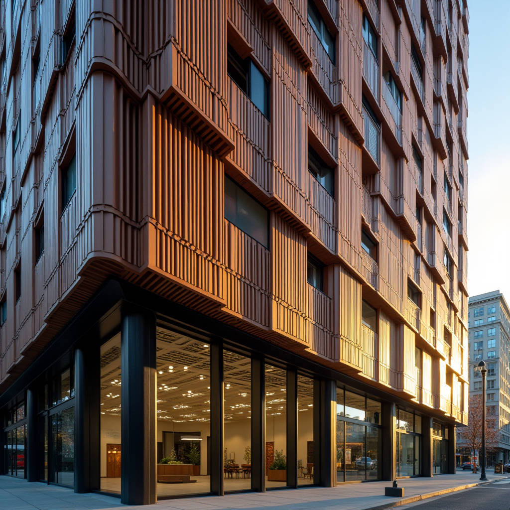
Specifying a woven aluminum facade means committing to a precise balance of visual rhythm and hard engineering. The term "woven" here does not refer to textile but to an architectural strategy where solid aluminum panels are arranged in overlapping, interlocking, or staggered patterns to mimic the warp and weft of fabric. This approach creates depth, shadow play, and a kinetic quality that flat rainscreen panels cannot deliver. For general contractors and facade engineers, the challenge sits at the intersection of pattern logic, panel flatness, and attachment hardware. A woven aluminum facade is not a standard modular system. It demands custom perforation mapping, non-sequential panel numbering, and a substructure that accommodates both the visual offset and the structural load path. Getting the specification right early prevents cost overruns during fabrication and installation. This article breaks down the technical layers that determine whether a woven aluminum facade performs as intended over a 30-year service life.
Defining the Woven Pattern in Solid Aluminum
Architects often arrive with a rendered concept showing a rhythmic, basket-like skin. Translating that into buildable solid aluminum panels requires the facade engineer to define the pattern module. A woven aluminum facade typically repeats every two, three, or four panel rows. The "weave" effect comes from alternating panel depths, typically 20mm to 60mm of offset between adjacent panels, combined with a directional grain or perforation shift. The module must align with the building grid, floor-to-floor height, and the location of vertical joints. If the module does not divide evenly into the floor height, the contractor ends up with slivers at the parapet or soffit, which kills the visual logic.
Solid aluminum panels for woven applications are typically specified at 2.5mm or 3.0mm thickness. The 2.0mm option works for standard flat rainscreens but tends to show oil-canning when panels exceed 600mm in width with a depth offset. The weave pattern itself introduces additional bending moments at the panel edges where the offset occurs. A 3.0mm panel with a 5052-H32 temper provides the stiffness needed to hold the offset without visible deflection under wind load. The temper matters as much as the thickness. H32 offers a balance of formability and strength, allowing the panel to be brake-formed into the offset profile without cracking at the bend radius.
Material Selection and Alloy Considerations
Not all aluminum alloys behave identically when formed into the complex geometries that a woven aluminum facade demands. The three alloys most commonly encountered in facade specification are 1100, 3003, and 5052. Each brings distinct characteristics to the table, and selecting the wrong one for a woven application leads to fabrication headaches or premature field failure.
| Alloy | Temper | Yield Strength (MPa) | Elongation (%) | Woven Pattern Suitability |
|---|---|---|---|---|
| 1100 | H14 | 110 | 9 | Low — commercial grade, limited stiffness, prone to oil-canning in offset panels |
| 3003 | H14 | 145 | 8 | Moderate — acceptable for shallow offsets (≤25mm), common in budget-driven projects |
| 5052 | H32 | 195 | 12 | High — preferred for woven aluminum facade with offsets ≥30mm, excellent corrosion resistance |
| 5754 | H22 | 185 | 14 | High — marine-grade alternative, superior elongation for deep draw forming |
The data points toward 5052-H32 as the workhorse for woven aluminum facade applications. Its higher yield strength means panels resist the bending stresses introduced by the weave offset. The 12% elongation figure is critical because it indicates the alloy can stretch during brake forming without micro-cracking. For coastal projects, 5754-H22 offers an upgrade path with better resistance to chloride-induced pitting. The cost premium for 5754 over 5052 runs approximately 12-18%, which the specifier must weigh against the project's distance from saltwater and anticipated maintenance cycles.
Perforation and Porosity Logic
Many woven aluminum facade designs incorporate perforations to enhance the textile analogy. The perforation pattern interacts with the weave geometry in ways that affect both appearance and structural behavior. A panel with 30% open area behaves differently under wind load than a solid panel of the same thickness. The effective wind area changes because air passes through the perforations, reducing the net pressure on the panel face. However, this reduction is not linear and depends on the hole diameter, spacing, and the presence of an acoustic backing layer.
For a woven aluminum facade with staggered perforation fields, the structural engineer must calculate the reduced section modulus at the perforated zone. A common approach is to treat the perforated region as having an effective thickness based on the ligament efficiency. If the panel has 6mm diameter holes at 12mm center-to-center spacing in a 60-degree staggered pattern, the ligament efficiency is approximately 0.50. The effective bending stiffness of the perforated zone drops to roughly half that of the solid parent material. This reduction must be accounted for in the deflection calculation under the project's design wind load, typically referenced to ASCE 7-22 for North American projects or EN 1991-1-4 for European work.
Perforation also affects the visual reading of the weave. When the perforation pattern shifts direction between alternating panels, the weave effect intensifies. A panel with vertical slot perforations placed next to a panel with horizontal slots creates a moiré-like depth that reinforces the woven aluminum facade concept. The fabrication challenge is maintaining registration between the perforation pattern and the panel edges. If the perforation field drifts by even 2mm across a 1200mm wide panel, the misalignment becomes visible at the vertical joint when panels are installed side by side.
Coating Systems and Weave Durability
The coating on a woven aluminum facade does more than deliver color. It protects the aluminum substrate from environmental degradation and must withstand the additional mechanical stress at the panel offset zones. The standard architectural coating for solid aluminum panels is PVDF (polyvinylidene fluoride), applied as a multi-coat system over a chrome-based conversion coating. The specification that governs this is AAMA 2605, which defines the highest performance tier for architectural coatings.
A woven aluminum facade introduces a specific coating challenge: the offset edges create zones where the coating film thickness can vary during the spray application. If the spray gun angle does not adequately cover the inside radius of the offset, the dry film thickness (DFT) may drop below the 30μm minimum required by AAMA 2605. The specifier should require the fabricator to measure DFT at the offset corners, not just on flat panel faces. A 3-coat PVDF system with a primer, color coat, and clear topcoat typically delivers 35-45μm total DFT on flat surfaces. At the offset inside radius, this can drop to 25-28μm if the application is not carefully controlled.
For projects in the Middle East or Southeast Asia, where UV exposure and humidity combine aggressively, a 4-coat system with a barrier primer adds approximately 8-10μm of additional protection. The cost adder is around 15% over the standard 3-coat system. The decision hinges on the project's distance from the equator and the specifier's tolerance for color fade over the warranty period. PVDF coatings on aluminum panels typically carry a 20-year film integrity warranty, but color change (Delta E) can exceed 5 units after 15 years in high-UV environments if the coating system is underspecified.
Substructure Design for Woven Geometry
The substructure behind a woven aluminum facade must solve a problem that standard rainscreen systems do not face: the panel plane is not flat. Alternating panels sit at different standoff distances from the structural wall. This means the help profiles, typically aluminum T-sections or hat channels, must be set at multiple depths. The contractor cannot simply install a uniform grid of vertical rails and clip panels onto it.
There are two approaches to managing the depth offset. The first uses a single-plane substructure with custom-depth panel brackets. Each bracket is fabricated to the specific standoff required for its panel position. This simplifies the rail installation but increases the bracket fabrication complexity. The second approach uses a stepped substructure where the vertical rails themselves are set at two or three different planes. This requires more rail material and more anchors into the structural backup, but it standardizes the panel brackets. The choice between these approaches depends on the weave pattern complexity and the contractor's tolerance for field adjustment.
Thermal isolation is non-negotiable in a woven aluminum facade substructure. The aluminum rails and brackets create thermal bridges that can compromise the building envelope performance. The solution is a thermally broken help system, where a polyamide or polyurethane isolator separates the exterior aluminum rail from the interior anchor. The effective thermal conductivity of the help connection should be below 0.25 W/m·K to meet the requirements of ISO 10211 for thermal bridge calculation. The cost of thermally broken help components adds approximately 8-12% to the substructure budget, but it is essential for any project targeting LEED, BREEAM, or Passive House certification.
Wind Load Behavior of Offset Panels
A woven aluminum facade with alternating panel depths creates a complex aerodynamic surface. The wind does not flow smoothly over the facade as it would over a flat rainscreen. The offsets generate turbulence, which can increase local pressure coefficients at the panel edges. The standard approach of applying a uniform pressure coefficient from a wind tunnel study or code table may underestimate the loads on the projecting panels.
The projecting panels in a woven aluminum facade act as small canopies or fins. They experience pressure on both the front face and, depending on the gap between panels, on the back face as well. If the gap between the projecting panel and the recessed panel is greater than 15mm, wind can enter the cavity and pressurize the back of the projecting panel. This net pressure coefficient can be 20-30% higher than the code value for a flat wall. The facade engineer should request a project-specific wind tunnel study when the weave offset exceeds 40mm or when the building height exceeds 60 meters.
Panel deflection under wind load is governed by the span between help attachment points. For a woven aluminum facade, the attachment points are typically at the panel corners, with intermediate clips along the vertical edges. The maximum allowable deflection is L/175 for aluminum panels per The Aluminum Association design guidelines, where L is the span between attachments. For a panel with 800mm vertical help spacing, the allowable deflection is 4.6mm. The engineer must check deflection in both the solid and perforated zones of the panel, using the reduced section properties for the perforated regions.
Fabrication Tolerances and Quality Control
The woven aluminum facade concept lives or dies on fabrication precision. A panel that is 1.5mm out of square becomes visibly misaligned when placed next to its neighbor in a staggered weave pattern. The cumulative effect of tolerance stack-up across a 20-panel-wide elevation can shift the pattern by 30mm, which is clearly visible from street level.
The fabricator must hold panel dimensions to ±0.5mm on length and width, and ±0.3mm on the offset depth. These are tighter than the standard ±1.0mm tolerance for flat rainscreen panels. Achieving this requires CNC brake presses with automatic angle correction, not manual bending. The perforation pattern must be registered to the panel edges with a tolerance of ±0.5mm. This means the CNC punching or laser cutting program must reference the same datum edges as the bending program. A mismatch in datums is the most common cause of pattern drift in woven aluminum facade fabrication.
Quality control for a woven aluminum facade project should include a first-article inspection of a full pattern module, typically 2x2 or 3x3 panels assembled on a mock-up frame. The mock-up reveals whether the pattern reads correctly at full scale and whether the panel-to-panel joints are consistent. It also allows the contractor to verify the installation sequence. Panels in a woven pattern are not interchangeable. Each panel has a specific position in the weave, and the panel numbering system must reflect this. A panel marked "W-3B" might indicate row 3, position B in the weave sequence. The installer must follow the numbering exactly, or the pattern breaks.
Installation Sequencing and Site Logistics
Installing a woven aluminum facade is fundamentally different from installing a standard flat rainscreen. The installer cannot simply start at one corner and work across the elevation. The weave pattern dictates the installation sequence. If the pattern module is four panels wide, the installer must set panels in groups of four to maintain the weave alignment. This means the help system must be complete and surveyed for the entire elevation before panel installation begins. Partial installation is not possible without risking pattern drift.
The panel packaging and delivery sequence must match the installation sequence. If panels arrive on site in fabrication order rather than installation order, the contractor spends time sorting through crates to find the correct panel for each position. This is a common source of delay and frustration on woven aluminum facade projects. The specification should require the fabricator to package panels in installation sequence, with each crate clearly labeled with the panel numbers and their position in the weave.
Handling damage is a particular concern for woven aluminum facade panels because the offset edges are vulnerable to impact. A panel dropped on its corner will deform the offset, and the deformation cannot be repaired on site. The damaged panel must be replaced, which means the fabricator must be able to produce a single replacement panel that matches the original exactly. This requires the fabricator to retain the CNC program and the specific coil of aluminum used for the original production. Suppliers like Futeng® who maintain digital fabrication records and coil traceability can produce replacement panels that match the original within tolerance, even months after the initial production run.
Cost Drivers and Budget Planning
The cost of a woven aluminum facade runs higher than a standard flat rainscreen for several reasons. The fabrication complexity adds labor hours. The tighter tolerances increase the scrap rate. The custom bracketry for the depth offset adds material and engineering cost. And the installation sequencing requires more skilled labor and more time on site.
A reasonable budget estimate for a woven aluminum facade with 3.0mm 5052-H32 panels, PVDF coating, and a thermally broken help system falls in the range of $85 to $140 per square foot of facade area, depending on the pattern complexity, perforation percentage, and project location. This compares to $55 to $80 per square foot for a standard flat solid aluminum rainscreen of the same material specification. The premium reflects the additional engineering, fabrication, and installation labor required to execute the weave pattern correctly.
The cost variables that most affect the budget are the number of unique panel types in the weave module, the perforation open area percentage, and the depth of the panel offset. A pattern with two panel types and a 20mm offset is significantly less expensive than a pattern with four panel types and a 50mm offset. The specifier should work with the fabricator early in the design phase to optimize the weave module for cost without sacrificing the architectural intent. Reducing the number of unique panel types from four to three can cut fabrication costs by 15-20% without visibly compromising the woven effect.
Maintenance and Long-Term Performance
A woven aluminum facade requires more attentive maintenance than a flat facade because the offset geometry creates horizontal surfaces where dust and debris can accumulate. In a flat rainscreen, rain washes most of the facade clean. In a woven aluminum facade, the projecting panels create sheltered zones on the recessed panels below. These zones do not receive direct rain washing and can develop visible soiling patterns over time.
The maintenance plan should include periodic cleaning at intervals determined by the local environment. In urban environments with moderate pollution, cleaning every 24 to 36 months is typically sufficient. In industrial or coastal environments, the interval may need to be 12 to 18 months. The cleaning method must be compatible with the PVDF coating. Pressure washing at up to 80 bar with a fan nozzle is generally safe, but the operator must maintain a minimum distance of 300mm from the panel surface to avoid damaging the coating. Abrasive cleaners and alkaline detergents with pH above 9 should be avoided entirely.
Inspection of the attachment hardware should be part of the maintenance cycle. The thermal cycling of the aluminum substructure can loosen fasteners over time. A visual inspection of accessible help connections every five years, with re-torquing as needed, prevents long-term degradation of the attachment system. The PVDF coating itself should be inspected for color change and gloss retention against the original warranty benchmarks. A Delta E measurement below 5 units and gloss retention above 50% of the original value are typical acceptance criteria after 10 years of service.
Specifying a woven aluminum facade is an exercise in managing the tension between architectural ambition and fabrication reality. The pattern module, alloy selection, coating specification, and substructure design are interdependent. A decision in one area constrains the options in another. The most successful projects are those where the architect, facade engineer, and fabricator collaborate from schematic design onward, resolving the weave logic before the tender documents are finalized.
The technical path is clear: specify 5052-H32 or 5754-H22 alloy at 3.0mm minimum thickness for offset panels, require AAMA 2605-compliant PVDF coating with DFT verification at the offset radii, design the substructure for the specific weave geometry rather than adapting a standard rainscreen system, and insist on a full-scale mock-up before production release. The cost premium over a flat facade is real, but so is the visual result. A properly executed woven aluminum facade delivers a depth and material presence that no flat panel system can match.