Woven Aluminum Mesh Facade Engineering Wind Loads Porosity and Structural Attachment Design
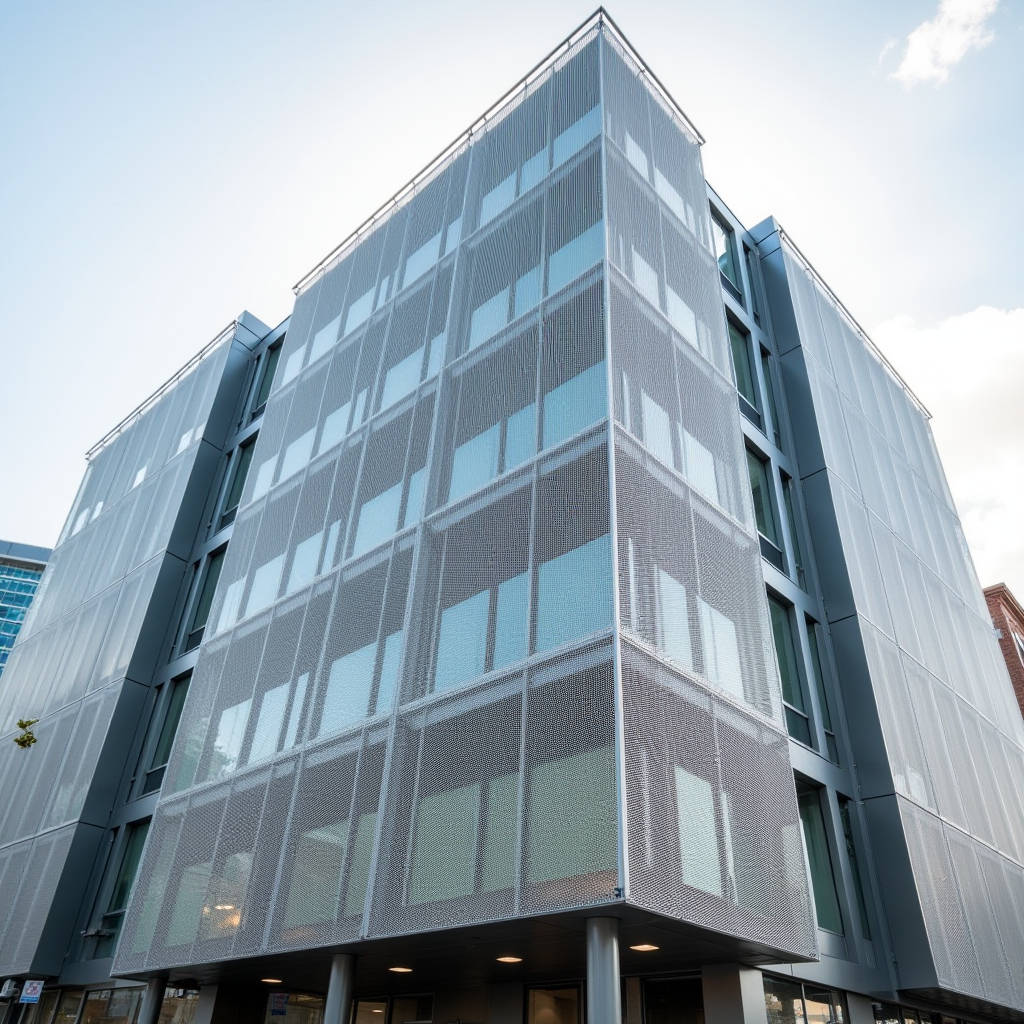
When a facade consultant specifies Woven Aluminum Mesh as a secondary skin on a high-rise, the conversation shifts quickly from aesthetics to structural load paths. The mesh itself is lightweight — aluminum woven wire mesh typically weighs between 0.8 and 4.5 kg/m² depending on wire diameter and open area percentage — but wind tunnel testing tells a different story. A 60% open area mesh can still transmit 40% to 55% of the wind pressure that a solid panel would experience, because the wires disrupt airflow and create localized pressure zones that standard building codes do not fully capture. Engineers who treat woven mesh as "transparent" in wind load calculations are making a costly assumption. The reality is that Woven Aluminum Mesh behaves as a partially porous barrier, and its structural impact on the primary support system — steel outriggers, aluminum mullions, or tension cables — must be quantified through computational fluid dynamics or physical wind tunnel testing, not rule-of-thumb porosity ratios.
How Porosity Numbers Mislead Structural Engineers
Manufacturers quote open area percentages for Woven Aluminum Mesh as a straightforward geometric calculation: the ratio of void space to total surface area. A plain weave with 3.5 mm wire diameter and 25 mm aperture spacing yields roughly 72% open area. But that number describes still-air conditions. Under wind loads of 1.5 kPa or higher, the boundary layer around each wire thickens, effectively reducing aerodynamic porosity. Research from the American Architectural Manufacturers Association (AAMA) and wind engineering studies on porous cladding indicate that aerodynamic porosity can be 15% to 25% lower than geometric porosity at wind speeds above 30 m/s. This discrepancy matters when you are designing attachment systems for a 40-meter-tall feature wall in a coastal city with a design wind speed of 45 m/s.
The practical consequence: a specifier who selects a 70% open area mesh assuming it will shed 70% of wind load may be under-designing the substructure by a factor of 1.3 to 1.6. On a project with 800 m² of mesh facade, this translates to several tons of unaccounted lateral force transferred to the building's primary structure. The fix is not to over-engineer everything — it is to treat the mesh as a partially loaded surface and apply pressure coefficients derived from testing rather than generic porosity tables.
Alloy Selection and the Corrosion Blind Spot
Most architectural Woven Aluminum Mesh is produced from 5052 or 5154 aluminum alloy wire. These magnesium-rich 5000-series alloys offer good atmospheric corrosion resistance, but they are not immune to degradation in specific environments. Coastal installations with chloride deposition rates above 60 mg/m²/day — common within 500 meters of breaking surf — can trigger intergranular corrosion in 5052 mesh if the wire has been cold-worked without proper stress relief. The weave process itself introduces residual tensile stress at each crimp point, creating micro-crevices where chloride ions concentrate.
Some mesh suppliers address this with anodized finishes, but anodizing woven mesh presents a technical challenge: the electrical contact points between intersecting wires create uneven current distribution during the anodizing process, resulting in coating thickness variations of 30% to 50% across the mesh surface. A more reliable approach for severe marine environments is specifying 5154 alloy with a post-weave PVDF liquid coating applied by dip-and-spin methods, achieving 25-35 microns of fluoropolymer coverage even in the crimp zones. This is a different process from the spray-applied PVDF used on solid aluminum cladding panels, and it requires careful quality control to avoid bridging between wires that would stiffen the mesh and alter its visual character.
Fatigue Behavior in Tensioned Mesh Systems
Architectural mesh installations frequently use tensioned systems — stainless steel cables threaded through edge hems, or pre-tensioned flat panels bolted to structural frames. The tensioning process introduces a static load, but the dynamic response under wind is where fatigue becomes relevant. Woven Aluminum Mesh in a tensioned configuration acts as a membrane with very low bending stiffness, meaning it responds to wind gusts by oscillating rather than resisting. The cyclic stress at each wire intersection can reach 15% to 30% of the wire's tensile yield strength during moderate wind events.
Aluminum does not have a true fatigue limit; even at low stress amplitudes, cumulative damage occurs over millions of cycles. For a mesh facade on a building in a region with frequent wind — Chicago, Wellington, or any exposed coastal city — the number of stress cycles over a 30-year service life can exceed 10⁷. Testing per ASTM E466 on 5052-O temper wire shows that the fatigue strength at 5×10⁷ cycles is approximately 40% of the ultimate tensile strength. This means a tensioned mesh system designed to 50% of UTS under static conditions may be operating near the fatigue threshold once dynamic effects are included. The conservative approach is to limit static tension to 25% of UTS and to specify wire with a minimum elongation of 8% to accommodate cyclic strain without crack initiation.
Thermal Expansion Compatibility with Support Structures
A less obvious failure mode involves differential thermal movement between the Woven Aluminum Mesh and its support frame. Aluminum wire mesh has a coefficient of thermal expansion of approximately 23.5 × 10⁻⁶ /°C. If the mesh is mounted on a steel frame (CTE ~12 × 10⁻⁶ /°C), a 50°C temperature swing over a 6-meter panel length produces a differential movement of roughly 3.5 mm. In a rigidly fixed mesh panel, this movement gets absorbed as buckling or sagging — visible as waves in the mesh that compromise the intended flat appearance.
The standard solution is to incorporate slotted connections or spring-loaded tensioners at one end of each panel, allowing the mesh to expand and contract independently of the frame. But this detail must be coordinated with the wind load strategy: a spring system that is soft enough to accommodate thermal movement may also allow excessive deflection under wind suction. The spring rate must be selected to balance thermal compliance (low stiffness) against wind resistance (high stiffness), and this balance point shifts with panel size and design wind pressure. For panels larger than 4 m², a staged spring system — soft initial travel for thermal movement, stiffer secondary travel for wind resistance — can resolve the conflict.
Fire Performance and Code Compliance Pathways
Woven Aluminum Mesh used on exterior facades falls under the scrutiny of building fire codes, particularly in jurisdictions that have adopted the International Building Code (IBC) with amendments for combustible cladding. Aluminum itself is non-combustible (it meets the ASTM E136 definition), but aluminum in thin wire form melts at approximately 660°C and can drip, potentially creating a secondary hazard. The mesh's open area works in its favor here: a 60% open area mesh allows significant heat and flame passage, which can actually reduce the temperature at the mesh plane compared to a solid panel.
Testing per NFPA 285 — the standard fire test for exterior non-load-bearing wall assemblies containing combustible components — is increasingly required for mesh facade systems in the United States, even when the mesh itself is non-combustible, because the assembly includes components like gaskets, sealants, and thermal barriers. A mesh system that passes NFPA 285 with a specific set of ancillary materials may fail if those materials are substituted. Specifiers should require full assembly test reports, not just material-level fire ratings, and should verify that the tested configuration matches the project's actual wall assembly.
Acoustic Implications of Perforated Metal Facades
Architects often specify Woven Aluminum Mesh for parking garages and mechanical equipment screens, where the primary function is visual screening and ventilation. But the acoustic performance of these installations deserves attention, particularly in urban settings where mechanical noise from the screened equipment can reflect off adjacent buildings. A mesh screen with 50% to 70% open area provides negligible sound transmission loss — roughly 2 to 4 dB in the 500 Hz to 2000 Hz range — meaning it does little to attenuate equipment noise.
However, the mesh can be integrated with acoustic absorber panels behind it, creating a system that combines visual screening with sound absorption. The mesh itself contributes to the acoustic performance by acting as a protective facing that prevents fiber shedding from mineral wool or fiberglass absorbers, while the open area allows sound waves to reach the absorptive material. The key design parameter is maintaining at least 40% open area in the mesh to avoid reflecting mid-frequency sound back toward the source. Below 40% open area, the mesh begins to act as a partial reflector, reducing the effectiveness of the absorber behind it.
Comparative Analysis of Mesh Attachment Methods
The method of attaching Woven Aluminum Mesh to its support structure determines not only the installed cost but also the long-term performance and maintainability. Three primary attachment systems dominate architectural applications: tensioned cable systems, framed panel systems, and direct-fixed systems. Each has distinct structural and economic characteristics that project teams should evaluate against the specific facade requirements.
| Attachment System | Typical Panel Size Range | Installed Cost (USD/m²)* | Wind Load Capacity | Thermal Movement Accommodation | Field Replacement Difficulty |
|---|---|---|---|---|---|
| Tensioned Cable (SS wire rope + edge grips) | Up to 12 m × 3 m | $320 – $580 | Moderate (limited by cable pre-tension) | Excellent (cables flex) | Moderate (re-tensioning required) |
| Framed Panel (aluminum angle frame + bolted mesh) | 1.2 m × 3.6 m typical | $240 – $410 | High (frame transfers load) | Good (slotted connections) | Easy (individual panel removal) |
| Direct-Fixed (mesh screwed to steel subframe) | 0.6 m × 1.2 m typical | $180 – $310 | Highest (rigid connection) | Poor (buckling risk) | Difficult (mesh damage during removal) |
| Modular Cassette (pre-fabricated mesh + subframe unit) | 0.9 m × 2.4 m typical | $380 – $620 | High (engineered system) | Good (cassette joints) | Very Easy (clip-in/out) |
*Cost ranges reflect 2024-2025 pricing for mid-rise commercial projects in North America, including labor, primary structure, and mesh material. Excludes design fees, access equipment, and freight.
For projects where the mesh serves as a visual feature over solid aluminum cladding panels — a common configuration where Woven Aluminum Mesh provides solar shading and texture while solid panels behind it deliver the weather barrier — the framed panel and modular cassette systems offer the most reliable integration. The solid aluminum panels, typically 2.5 mm or 3.0 mm thick with PVDF coating per AAMA 2605, are installed as the primary rainscreen, and the mesh panels are mounted on outrigger brackets that span the cavity. This approach requires careful coordination of the bracket penetrations through the weather barrier, but it decouples the two systems structurally, allowing each to perform independently.
Specifying Mesh Geometry for Visual Consistency
One of the most frequent complaints from architects about Woven Aluminum Mesh installations is visual inconsistency across panel joints. The weave pattern — whether plain weave, twill weave, or Dutch weave — creates a directional texture that can appear to shift when adjacent panels are not aligned. This is particularly noticeable with coarse meshes where the wire diameter exceeds 2.0 mm and the aperture spacing is greater than 15 mm.
The solution is to specify panel orientation and weave direction on the shop drawings, and to require that all panels be cut from the same production batch of mesh. Wire diameter tolerances of ±0.05 mm are standard for architectural-grade aluminum woven wire mesh, but even within this tolerance, a 0.1 mm difference between two batches can create a perceptible line at the panel joint when viewed from acute angles. Batch-level consistency is more important than absolute dimensional accuracy for visual applications.
Additionally, the mesh should be specified with a defined "viewing side" — the side that will face outward. During the weaving process, one side of the mesh (the "tool side") contacts the weaving machine's reed and may show slight surface marks or a marginally different texture than the opposite side. For architectural applications where the mesh is viewed from close range, specifying the "non-tool side" as the exposed face eliminates this source of visual variation.
Integration with Solid Aluminum Cladding Systems
When Woven Aluminum Mesh is used as a shading layer in front of solid aluminum cladding panels, the two systems must be engineered as a coordinated assembly rather than two independent scopes. The cavity depth between the mesh and the solid panel affects both the shading performance and the wind pressure distribution. A cavity depth of 150 mm to 300 mm is typical, providing sufficient airflow to prevent heat buildup while allowing access for cleaning and maintenance.
The solid aluminum panels behind the mesh — manufactured from 5052-H32 or 3003-H14 alloy sheet at 2.5 mm or 3.0 mm thickness with a PVDF fluoropolymer coating system meeting AAMA 2605 requirements — serve as the primary air and water barrier. The mesh outrigger brackets must be designed with thermal breaks at the attachment points to the solid panel support system, preventing thermal bridging that could compromise the thermal performance of the overall wall assembly. Suppliers like Futeng® who manufacture both solid aluminum cladding panels and coordinate with mesh fabricators can provide integrated shop drawings that resolve these interface details before fabrication begins, reducing field coordination issues.
Maintenance Access and Long-Term Serviceability
Woven Aluminum Mesh facades accumulate dirt differently than solid cladding. The wire surfaces catch airborne particulates, and in areas with high humidity, biological growth — algae, lichen — can establish on the wire surfaces, particularly in the crimp zones where moisture lingers. The open area of the mesh means that rain does not effectively wash the wire surfaces; water droplets tend to pass through the openings rather than sheet across the wires.
Cleaning access must be designed into the system from the start. For mesh panels installed over solid aluminum cladding, the cavity must be wide enough to accommodate a pressure washer wand or a brush tool, and the mesh panels should be removable without destroying the fasteners. Stainless steel fasteners with anti-seize compound are essential — aluminum and stainless steel in contact create a galvanic couple, and without isolation, the aluminum wire around the fastener holes will corrode within a few years in any environment with moisture.
A maintenance schedule of annual inspection and cleaning every 3 to 5 years is reasonable for most urban environments. Coastal installations may require cleaning every 12 to 18 months to remove salt deposits. The cost of access equipment — swing stages, boom lifts, or rope access teams — often exceeds the cost of the cleaning itself, which is why the modular cassette systems that allow individual panel removal from inside the building offer a long-term cost advantage for high-rise applications.
Specifying Woven Aluminum Mesh for architectural facades requires navigating a matrix of structural, thermal, acoustic, and maintenance considerations that go well beyond selecting a weave pattern and an alloy. The successful projects treat the mesh as an engineered facade component, not a decorative afterthought, and invest in the interface details — attachment hardware, thermal movement accommodation, and access strategy — that determine whether the installation performs reliably over a 30-year service life. Wind tunnel data, fatigue analysis, and assembly-level fire test reports are not optional extras; they are the documentation that separates a properly specified system from one that creates liability for the design team and the contractor.