Laser Cut Aluminum Facade Structural Engineering and Perforation Design Guide
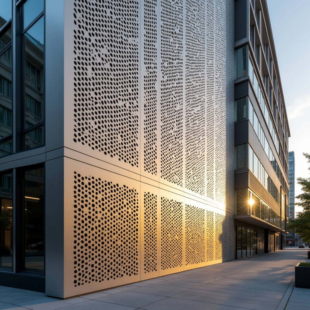
When a building envelope fails to perform, the fault rarely lies with a single material. More often, the culprit is a mismatch between aesthetic ambition and structural reality. Laser Cut Aluminum Facade systems sit precisely at this intersection, where decorative perforation patterns must coexist with wind loads, thermal movement, and decades of weather exposure. Getting the specification right means understanding what happens to a 3mm solid aluminum sheet after thousands of precision cuts remove material from its surface. This article examines the structural engineering considerations that architects and facade contractors need to address before finalizing any laser-cut aluminum cladding design, with particular attention to how perforation ratios affect panel stiffness, how different aluminum alloys behave under cyclic loading, and what attachment methods actually work when standard clip systems meet non-standard hole patterns.
How Perforation Ratios Reshape Panel Stiffness
Every hole cut into a solid aluminum sheet reduces its effective cross-sectional area. The relationship is not linear. A panel with 30% open area does not retain 70% of its original stiffness, it typically retains somewhere between 40% and 55%, depending on hole geometry and spacing. This matters because facade engineers calculate deflection limits based on the assumption of a continuous, unperforated plate.
The standard deflection limit for aluminum cladding under wind load is L/175 for spans up to 3 meters, per ASTM E330. A 3mm thick 5052-H32 aluminum panel spanning 1,200mm between supports might deflect 4.2mm under a design wind pressure of 1.5 kPa when solid. That same panel, laser-cut with a 35% open area in a staggered circular pattern, could deflect 9.8mm under identical loading. The difference pushes many designs beyond allowable limits without the specifier realizing it.
Finite element analysis becomes essential rather than optional once perforation ratios exceed 20%. The stress concentration at the edges of laser-cut openings creates localized zones where the aluminum yields at lower overall panel loads than the gross-section calculation would predict. Sharp internal corners, a common feature in geometric cut patterns, amplify this effect. A circular hole produces a stress concentration factor of approximately 3.0, while a square hole with a 2mm corner radius pushes that factor above 4.5. For reference, the Aluminum Association's Aluminum Design Manual provides detailed guidance on calculating net section properties for perforated members.
Alloy Selection and the Temper Question
Not all aluminum handles post-cut stress the same way. The laser cutting process introduces a heat-affected zone along the cut edge, typically 0.1mm to 0.3mm wide depending on laser power and cutting speed. For 3003-H14 alloy, this zone sees a localized reduction in tensile strength from approximately 150 MPa to 130 MPa. For 5052-H32, the drop is smaller, from 230 MPa to roughly 215 MPa, because the magnesium content in 5052 provides better retention of mechanical properties after thermal cycling.
The practical implication: 5052-H32 should be the minimum specification for any Laser Cut Aluminum Facade panel with open areas exceeding 25%. The 5000 series alloys offer superior corrosion resistance in coastal and industrial environments, which matters because laser-cut edges expose more raw aluminum surface area to atmospheric attack than a solid panel ever would. Each cut edge represents a potential initiation point for pitting corrosion if the pretreatment and coating system does not fully encapsulate it.
For projects in aggressive marine environments, 5754 or 5083 alloys provide even better resistance to chloride-induced stress corrosion cracking. These alloys cost approximately 18-25% more than 5052 but eliminate the need for edge touch-up treatments that field crews often apply inconsistently.
| Alloy Grade | Yield Strength (MPa) | Tensile Strength (MPa) | Corrosion Resistance | Post-Cut Strength Retention | Relative Cost |
|---|---|---|---|---|---|
| 3003-H14 | 145 | 150-200 | Moderate | ~87% | 1.0x |
| 5052-H32 | 193 | 228-275 | High (Marine OK) | ~93% | 1.15x |
| 5754-H22 | 190 | 250-290 | Very High | ~94% | 1.35x |
| 5083-H116 | 228 | 305-345 | Excellent (Offshore) | ~95% | 1.50x |
Attachment Systems That Work With Perforated Panels
Standard aluminum cladding attachment relies on the panel having sufficient material around fastener locations to transfer wind loads into the subframe. When laser-cut patterns remove material from the panel perimeter, the remaining web of aluminum at attachment points must be analyzed independently of the decorative field.
Three attachment strategies have proven reliable across multiple completed projects:
1. Solid Perimeter Frame Method. The laser-cut pattern stops 40-60mm from all panel edges, leaving a continuous solid border for fastener engagement. This approach preserves the full structural capacity of the panel at attachment points and allows the use of standard cassette or tray systems. The trade-off: visible unperforated margins alter the visual continuity, particularly at panel joints where two solid borders meet.
2. Welded Reinforcement Ribs. For projects where the pattern must extend to the panel edge, 2mm thick aluminum stiffener ribs are MIG-welded to the panel rear along vertical and horizontal lines between attachment points. The ribs carry the wind load, and the perforated face sheet acts primarily as a decorative screen. This approach adds approximately 2.8-3.5 kg/m² to panel weight and requires careful quality control on weld penetration to avoid burn-through on the visible face.
3. Subframe-Grid Attachment. A secondary grid of aluminum channels is mounted behind the perforated panel, with the panel attached at multiple intermediate points rather than only at the perimeter. This distributes loads more evenly and reduces the span between supports, bringing deflection back within limits. The subframe grid itself must be designed to accommodate differential thermal expansion between the perforated face sheet and the supporting structure. Aluminum expands at roughly 2.4mm per meter per 100°C temperature change. A 3-meter panel in a dark color facing direct sun can see surface temperatures swing from -10°C to +80°C, producing 6.5mm of expansion that the attachment system must absorb without buckling the panel.
Coating Integrity Across Cut Edges
The single most common failure mode in Laser Cut Aluminum Facade installations is coating delamination initiating at cut edges. PVDF (polyvinylidene fluoride) coatings, the industry standard for architectural aluminum per AAMA 2605, are applied to the sheet before laser cutting. The cutting process vaporizes the coating along the cut path and exposes bare aluminum at the edge face.
Pretreatment quality determines whether that exposed edge becomes a corrosion site. A proper chromate conversion coating applied before the PVDF topcoat provides sacrificial protection that extends approximately 0.5mm beyond the visible cut edge through a galvanic mechanism. Without this pretreatment, moisture ingress at the cut edge can undercut the PVDF coating within 2-3 years in humid climates.
Powder coating offers an alternative. Polyester powder applied at 60-80 microns thickness flows into micro-irregularities at cut edges better than liquid PVDF, which tends to pull back from sharp edges during curing due to surface tension effects. The trade-off: powder coating provides approximately 60% of the UV resistance of PVDF, making it suitable for sheltered applications but risky for full-sun exposure in latitudes below 35 degrees.
For projects specifying PVDF on laser-cut panels, the specification should mandate a minimum 5-stage pretreatment process: alkaline cleaning, water rinse, chromate conversion coating, water rinse, and seal rinse. The AAMA 2605 standard covers the performance requirements for the coating system, but specifiers should add a supplementary requirement for edge-coating coverage verified by dye-penetrant testing on sample panels.
Wind Load Engineering for Perforated Facades
Perforated panels interact with wind differently than solid panels. The openings allow partial pressure equalization between the exterior and the cavity behind the panel, which reduces the net pressure differential. However, this reduction is not uniform across the panel surface and depends heavily on the open area ratio and the ventilation characteristics of the cavity.
ASCE 7 provides guidance on partially open buildings, but its application to perforated cladding requires engineering judgment. A conservative approach treats the panel as solid for wind load calculations, which overestimates loads but provides a safety margin. A more refined approach, validated by wind tunnel testing on several projects, applies a reduction factor of (1 - open area ratio)^0.5 to the design wind pressure. For a panel with 40% open area, this yields a reduction factor of 0.77.
The cavity depth behind the panel matters. Cavities shallower than 50mm restrict airflow and reduce pressure equalization. Cavities deeper than 150mm allow full pressure development and maximize the reduction effect. The ASCE 7-22 standard provides the baseline wind load calculation methodology, but project-specific wind tunnel testing remains the gold standard for complex geometries.
Thermal Movement and Pattern Distortion
Laser-cut patterns introduce thermal expansion behavior that differs from solid panels. The same open area that reduces wind load also reduces the panel's cross-sectional area for thermal stress development. A 35% open area panel develops approximately 35% less thermal stress than a solid panel of the same dimensions. This sounds beneficial, but it creates a mismatch at the panel perimeter where the solid border (if present) expands at a different rate than the perforated field.
This differential expansion can produce visible warping at the transition zone between perforated and solid areas, particularly on panels larger than 2m². The solution is to design the perforation pattern with a gradual transition zone, where hole density decreases from the field value to zero over a 30-50mm band at the panel edges, rather than an abrupt stop.
Futeng® has documented this transition-zone approach across multiple large-scale facade projects, where the gradual reduction in perforation density eliminated the warping that appeared in earlier installations with abrupt pattern terminations. The additional engineering effort required for the transition zone design adds approximately 3-5% to the panel fabrication cost but eliminates the far more expensive prospect of field replacement for warped panels.
Fabrication Tolerances and Quality Control
Laser cutting aluminum sheet for architectural facades demands tighter tolerances than industrial laser cutting applications. The visual nature of facade panels means that kerf width consistency, cut edge squareness, and pattern registration across panel joints are all visible quality metrics.
Modern fiber laser cutting systems achieve positioning accuracy of ±0.05mm and kerf widths as narrow as 0.15mm in 3mm aluminum. However, the thermal effects of cutting can produce a slight taper in the cut edge, typically 0.02-0.04mm wider at the top than the bottom of the cut. For most patterns, this taper is invisible. For patterns with extremely fine detail or narrow webs between adjacent cutouts, the taper can produce visible asymmetry.
The practical specification limit: minimum web width between adjacent cutouts should be no less than 1.5 times the material thickness. For 3mm aluminum, that means a minimum web of 4.5mm. Narrower webs risk distortion during cutting, handling, and thermal cycling. The ISO 2768-1 tolerance class "m" (medium) provides a reasonable baseline for cut feature dimensions, but facade projects with visible panel joints should specify class "f" (fine) for pattern features within 50mm of panel edges to ensure visual alignment across joints.
Pattern Registration Across Panel Joints
When a laser-cut pattern spans multiple panels, the visual continuity at the joint depends on the pattern being cut with reference to a common datum. Fabricators who cut each panel independently, referencing the pattern to the panel center, will produce joints where the pattern misaligns by the cumulative tolerance of panel dimensions plus cut positioning.
The correct approach: establish a global grid origin for the entire facade elevation, and cut every panel with reference to that origin. This requires the fabricator to track each panel's position in the facade grid and offset the laser cutting program accordingly. The additional programming effort is minimal, but the quality outcome is dramatic. Misalignment at panel joints drops from potentially visible 2-3mm offsets to sub-millimeter accuracy.
Cost Drivers Beyond the Square Meter Rate
Procurement teams evaluating Laser Cut Aluminum Facade panels often compare square-meter prices without accounting for the factors that drive total installed cost. The per-square-meter fabrication cost of a laser-cut panel depends primarily on three variables: cut length per panel, material utilization rate, and secondary processing requirements.
Cut length is the dominant factor. A panel with a dense pattern of small holes might have 15 meters of cut length per square meter of panel area. A panel with larger, more widely spaced cutouts might have only 6 meters. Laser cutting time scales almost linearly with cut length, and machine time typically costs $2.50-$4.00 per minute depending on the equipment and region. A single square meter of densely patterned panel can require 45-60 minutes of laser time.
Material utilization, the percentage of the raw sheet that ends up in finished panels, drops as pattern complexity increases. Simple rectangular panels with no cutouts achieve 85-90% utilization. Panels with complex perimeter shapes and internal cutouts might achieve only 60-70%. The difference between 90% and 65% utilization on a 500m² project at $45/m² for 5052-H32 sheet material translates to approximately $8,700 in additional material cost.
Secondary processing, including deburring, edge treatment, and any post-cut forming or welding, adds $12-$25 per square meter depending on complexity. Specifiers should request a detailed cost breakdown that separates material, laser time, and secondary processing so that value-engineering decisions can target the actual cost drivers rather than making arbitrary pattern simplifications that compromise the design intent.
Installation Sequencing and Site Handling
Perforated aluminum panels are more susceptible to handling damage than solid panels. The reduced cross-sectional area means that a point load from improper lifting or stacking can permanently deform the panel at loads that a solid panel would resist without damage. Site teams accustomed to handling solid cladding panels need specific guidance.
Panels should be transported and stored vertically in purpose-built stillages with padded dividers that support the panel along its full height. Horizontal stacking, even with interleaving, concentrates loads on the perforated field and produces visible distortion. Lifting should use vacuum cup systems with at least four cups per panel, positioned to distribute the lifting force across the solid perimeter rather than the perforated field.
Installation sequence matters because perforated panels cannot be field-modified as easily as solid panels. A solid panel can be trimmed on site with a circular saw if dimensions are slightly off. A laser-cut panel with a perimeter pattern cannot be trimmed without destroying the pattern continuity. This means that the supporting subframe must be installed and surveyed to a tighter tolerance than for solid panel cladding, typically ±3mm across any 3-meter span versus ±5mm for standard systems.
Long-Term Performance Verification
Specifying a Laser Cut Aluminum Facade without a plan for performance verification transfers risk to the building owner. The specification package should include requirements for mock-up testing that covers the specific failure modes relevant to perforated panels.
A minimum test program includes: wind load testing to 1.5 times design pressure on a full-scale mock-up incorporating at least two full panels and one joint, per ASTM E330; water penetration testing under static pressure per ASTM E331; and coating adhesion testing per AAMA 2605 on cut edges specifically, not just on flat surfaces. The mock-up should be exposed to outdoor conditions for a minimum of 90 days before final acceptance, with inspection for edge corrosion, coating delamination, and pattern distortion at 30-day intervals.
The cost of a proper mock-up program, typically $8,000-$15,000 for a medium-complexity facade, represents a fraction of the cost of remediating systemic failures after installation. For projects exceeding 1,000m² of laser-cut cladding, the mock-up cost amortizes to less than $15 per square meter, a reasonable insurance premium against the risk of full-facade replacement.
Solid aluminum cladding with laser-cut patterns offers architectural possibilities that no other material system can match. The engineering path to a successful installation runs through honest assessment of perforation ratios, alloy selection matched to environment, attachment design that respects the reduced structural capacity of cut panels, and coating systems specified with edge protection as a primary requirement rather than an afterthought. When these technical foundations are in place, the visual result speaks for itself.