Twisted Aluminum Panel Engineering From Alloy Selection to Facade Installation
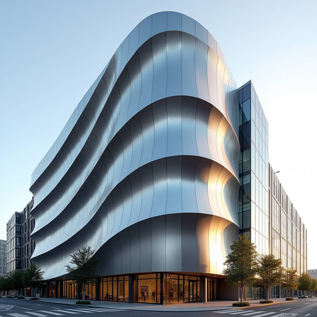
When a facade design brief calls for a surface that rotates through three-dimensional space, standard flat panels and even single-curved sheets fall short. A Twisted Aluminum Panel is the answer: a solid aluminium sheet engineered with controlled torsion along one or more axes, producing a helical or spiraling geometry that flat stock simply cannot replicate. Unlike double-curved panels that bend in two directions simultaneously, a twisted panel introduces rotational deformation—the material rotates around a longitudinal axis, creating a dynamic visual flow that architects use to break away from static, orthogonal building envelopes. The technical challenge lies in achieving this torsion without wrinkling, thinning, or compromising the structural integrity of the metal. This article examines the fabrication methods, alloy selection, tolerance control, and installation logic that determine whether a twisted aluminium facade performs as intended over decades of service.
The Geometry Problem: What Makes a Panel "Twisted"
In metal fabrication, bending and twisting are fundamentally different operations. Bending applies force along a single plane to create a radius. Twisting applies rotational torque around a longitudinal axis, causing the cross-section to rotate progressively from one end of the panel to the other. The result is a surface where no two adjacent cross-sections share the same orientation.
For architectural cladding, a twisted panel typically features a controlled angular displacement—commonly between 5° and 60° over a panel length of up to 6 meters. The torsion can be uniform (constant rate of rotation per linear meter) or variable (accelerating or decelerating along the length). Some projects demand multi-axis twisting, where the panel rotates around two different axes simultaneously, producing compound helical geometries.
The key parameters that define a twisted panel specification include:
- Twist angle (θ): Total angular displacement from end to end, measured in degrees
- Twist rate: Degrees of rotation per linear meter of panel length
- Axis of rotation: Whether the twist occurs around the centroidal axis, one edge, or an offset axis
- Cross-sectional profile: Whether the panel maintains a constant section or tapers along its length
- Handedness: Left-hand or right-hand twist direction, critical when panels are mirrored across a facade
These parameters must be locked down during the design development phase. Changing the twist angle after tooling has been fabricated can add weeks to lead times and significant cost to the project budget.
Alloy Selection: Why 6xxx Series Dominates Twisted Panel Production
Not every aluminium alloy can survive the twisting process. The material must balance ductility for forming with strength for in-service performance. Through extensive shop floor experience, the industry has converged on specific grades within the 6xxx series (Al-Mg-Si) as the optimal choice for twisted architectural panels.
| Alloy Grade | Temper | Yield Strength (MPa) | Elongation (%) | Suitability for Twisting | Typical Application |
|---|---|---|---|---|---|
| AA 3003 | H14 | 145 | 8-10 | Poor — prone to cracking at twist angles above 15° | Not recommended for twisted panels |
| AA 5052 | H32 | 195 | 12-14 | Moderate — limited to low-angle twisting | Minor twisted elements, interior features |
| AA 6061 | T4 | 145 | 22 | Excellent — high ductility before artificial aging | Complex twisted panels, formed in T4 then aged to T6 |
| AA 6063 | T5 | 145 | 12-16 | Good — suitable for moderate twist angles | Extruded twisted profiles, mullions |
| AA 5754 | H111 | 190 | 18 | Very Good — high ductility with decent strength | Coastal twisted panels requiring corrosion resistance |
The standout performer is AA 6061 in the T4 temper. With 22% elongation, it can accommodate aggressive twist angles without fracturing. After forming, the panels undergo artificial aging to reach T6 temper, which boosts yield strength to approximately 275 MPa. This two-stage approach—form in T4, strengthen to T6—is the standard workflow for high-performance twisted panels. Fabricators who attempt to twist T6 material directly often encounter springback issues and micro-cracking along the torsion axis.
For projects in coastal or marine environments, AA 5754-H111 deserves serious consideration. Its magnesium content (2.6-3.6%) provides superior corrosion resistance compared to 6xxx alloys, and its 18% elongation handles moderate twisting well. The trade-off is a slightly lower final strength, which may require thicker gauge material to meet wind load requirements.
Fabrication Methods: Press Forming vs. Incremental Twisting
Two primary manufacturing routes exist for producing twisted aluminium panels, and the choice between them carries significant implications for cost, lead time, and achievable geometry.
Press Forming with Custom Dies
For high-volume production—typically projects requiring 200 or more identical twisted panels—press forming with dedicated tooling is the most economical path. A matched die set is machined from steel or high-density tooling board, with the upper and lower dies incorporating the precise twist geometry. The aluminium sheet is placed between the dies and subjected to controlled pressure, often in a hydraulic press with multi-point cushion systems that allow the material to flow into the twisted configuration.
The upfront tooling cost is substantial—expect USD 8,000 to 25,000 per die set depending on panel dimensions and complexity—but the per-unit cost drops dramatically once the dies are in production. Cycle times of 3-5 minutes per panel are achievable, and repeatability is excellent, with dimensional variation typically held within ±1.0 mm across production runs.
The limitation is geometric flexibility. Each die set produces one specific twist configuration. If the architect revises the twist angle mid-project, new dies are required. Additionally, press forming works best with uniform twist rates; variable-rate twisting often requires segmented dies that increase tooling complexity and cost.
Incremental Sheet Forming and CNC Twisting
For bespoke projects with varying twist parameters across panels, incremental forming methods are increasingly common. CNC-controlled twisting machines grip the panel at both ends and apply rotational torque while the material is supported by an array of adjustable anvils or rollers. The twist angle, rate, and axis can be programmed per panel, allowing a single machine to produce dozens of unique geometries without dedicated tooling.
This approach eliminates die costs entirely, making it attractive for low-volume, high-variation projects. The trade-off is cycle time: each panel may require 15-45 minutes to form, depending on complexity. Dimensional accuracy is also slightly lower than press forming, with tolerances typically in the ±2.0 mm range. However, for projects where no two panels are identical—such as parametric facades driven by computational design algorithms—incremental twisting is often the only viable manufacturing strategy.
Some fabricators, including Futeng®, employ a hybrid approach: press forming for the primary twist geometry followed by CNC-controlled secondary twisting for fine-tuning. This combines the speed of die-based production with the flexibility of programmable adjustment, achieving ±1.5 mm tolerances on complex geometries.
Springback: The Hidden Variable That Destroys Facade Alignment
Every metal forming operation involves elastic recovery—the material's tendency to partially return to its original shape after the forming force is released. In twisted panels, springback manifests as a reduction in the achieved twist angle compared to the tooling angle. A die cut to produce a 45° twist might yield a panel with only 38-40° of permanent twist, depending on alloy, temper, and panel thickness.
Compensating for springback requires empirical data. Experienced fabricators maintain databases of springback coefficients for each alloy-temper-thickness combination. For AA 6061-T4 at 2.5 mm thickness, a typical springback factor is 1.12 to 1.18—meaning the die must be cut to over-twist by 12-18% to achieve the target angle. For AA 5754-H111, the factor is closer to 1.08-1.12 due to its lower yield strength.
Springback is not uniform across the panel. The central region of a twisted panel experiences different strain levels than the edges, leading to differential springback that can produce subtle warping. This is particularly problematic on large panels exceeding 3 meters in length, where even 0.5° of angular variation at the center translates to several millimeters of edge displacement at the panel corners.
Mitigation strategies include:
- Over-twisting dies by the empirically determined springback factor
- Post-form heat treatment to relieve residual stresses before final inspection
- Restrike operations where the panel is re-pressed after initial springback
- Laser scanning verification of every panel against the 3D model to catch deviations early
For critical facade projects, specifying a maximum angular deviation of ±1.0° from the design twist angle is a reasonable and achievable tolerance. Tighter tolerances (±0.5°) are possible but increase rejection rates and cost.
Surface Finishing Twisted Panels: The Coating Challenge
Applying a uniform architectural finish to a twisted surface introduces challenges that flat panel coaters rarely encounter. The three-dimensional geometry creates shading effects during spray application, and the varying surface orientation relative to the spray gun can produce inconsistent film thickness.
PVDF (polyvinylidene fluoride) coatings remain the industry standard for exterior twisted panels. The AAMA 2605 specification requires a minimum total film thickness of 30-35 microns for a two-coat system and 40-45 microns for a three-coat system. On twisted surfaces, maintaining this thickness across all areas demands skilled manual spraying or advanced robotic systems with articulated arms that maintain consistent gun-to-surface distance and angle.
The coating sequence for a twisted panel typically follows this workflow:
- Pre-treatment: Alkaline cleaning followed by chromium or titanium-based conversion coating per ASTM D1730
- Prime coat: 5-10 microns of epoxy or polyurethane primer for corrosion protection and adhesion
- Color coat: 20-25 microns of PVDF color coat, applied in multiple passes to ensure coverage on all surfaces
- Clear coat: 10-15 microns of PVDF clear topcoat for UV resistance and gloss control
- Curing: Peak metal temperature of 232-249°C (450-480°F) for 8-10 minutes
Color consistency across twisted panels is harder to achieve than on flat stock. The human eye perceives color differently on curved versus flat surfaces due to the way light reflects at varying angles. A panel that matches perfectly when viewed head-on may appear slightly different when the twisted geometry catches light from a different angle. This is not a coating defect—it is an optical phenomenon inherent to three-dimensional surfaces. Setting expectations with the architect and facade consultant early prevents disputes during installation.
For interior twisted panels, polyester powder coating per AAMA 2603 is a cost-effective alternative. The electrostatic application process provides good wrap-around coverage on twisted geometries, and the cured film thickness of 60-80 microns offers decent durability for indoor environments. However, polyester coatings lack the UV resistance required for exterior use and will chalk and fade within 3-5 years if exposed to direct sunlight.
Wind Load Performance: Why Twisted Panels Need Special Engineering
A twisted panel interacts with wind differently than a flat panel. The rotating surface geometry creates complex aerodynamic effects: wind flowing across a twisted facade generates varying pressure distributions that cannot be accurately modeled using the simplified calculation methods in ASCE 7 or EN 1991-1-4 for rectangular flat plates.
The primary concern is torsional wind loading. As wind flows across a twisted panel, the changing surface orientation relative to the wind direction produces a twisting moment in addition to the normal positive and negative pressures. This moment tries to rotate the panel about its mounting points, introducing stresses that flat panel connection systems are not designed to handle.
For preliminary design, the following approach provides reasonable estimates:
- Calculate the basic wind pressure using the local building code (ASCE 7-16 in the US, EN 1991-1-4 in Europe, AS/NZS 1170.2 in Australia/New Zealand)
- Apply a shape factor of 1.3 to 1.8 for twisted surfaces, depending on twist angle and panel aspect ratio
- Add a torsional load case equivalent to 15-25% of the normal pressure acting at the panel's quarter-chord point
- Verify connection capacity under combined normal and torsional loading
For complex projects, computational fluid dynamics (CFD) analysis or wind tunnel testing of a representative facade mockup is strongly recommended. The cost—typically USD 15,000-40,000—is modest compared to the liability of a facade failure.
Panel thickness selection must account for the additional stresses from twisting during fabrication. A 2.5 mm thick AA 6061-T6 panel that easily handles wind loads when flat may develop stress concentrations along the twist axis that reduce its effective strength. As a rule of thumb, twisted panels should be specified one gauge thicker than the equivalent flat panel for the same wind load. If a flat panel at 2.0 mm meets the structural requirements, specify 2.5 mm for the twisted version.
Connection Design: Mounting Systems for Rotated Geometries
Standard curtain wall connection systems assume panels are planar. When a twisted panel is mounted to a flat substrate or framing system, the connection points must accommodate the angular mismatch between the panel's rotated surface and the building's structural grid.
Three connection strategies are commonly used:
1. Adjustable Bracketry: Each connection point uses a bracket with angular adjustment capability, typically ±15° in two axes. The bracket is bolted to the building structure and the panel is attached via slotted holes that allow fine positioning. This is the most flexible approach and works well for panels with twist angles up to 30°.
2. Stepped Sub-framing: A secondary framing system is installed between the primary structure and the panels. This sub-frame follows the twisted geometry, providing a conforming mounting surface. The panels attach to the sub-frame using standard connections. This approach adds material and labor cost but simplifies panel fabrication and replacement.
3. Integrated Panel Ribs: The panel is fabricated with integral stiffening ribs that double as connection points. The ribs are positioned to align with the building's structural grid, and the panel geometry bridges the gap between the twisted surface and the flat connection plane. This is the most elegant solution but requires close coordination between panel fabrication and structural engineering.
Regardless of the connection strategy, all mounting hardware for exterior twisted panels must be stainless steel—grade 316 for coastal environments, 304 for inland applications. Galvanized steel fasteners in contact with aluminium will cause galvanic corrosion, particularly in the presence of moisture. The AAMA TIR-A9 design guide provides detailed recommendations for metal-to-metal contact in architectural applications.
Thermal Movement: Accounting for Differential Expansion
Aluminium expands and contracts at approximately 23.4 × 10⁻⁶ per °C. A 4-meter twisted panel subjected to a 50°C temperature swing will change length by about 4.7 mm. On a flat panel, this movement is accommodated by leaving gaps at panel joints. On a twisted panel, thermal expansion introduces an additional complication: as the panel lengthens, the twist angle per unit length changes slightly, which can alter the panel's geometry enough to affect joint alignment.
The practical solution is to fix the panel at one end and allow the other end to float. The fixed point should be at the panel's geometric center or at the end with the most critical alignment requirement. All other connection points should incorporate slotted holes oriented parallel to the direction of thermal movement. The slot length should accommodate the calculated thermal movement plus a 50% safety margin.
For projects in regions with extreme temperature ranges—such as the Middle East, where daytime surface temperatures can exceed 80°C and nighttime temperatures drop below 20°C—thermal movement calculations should use the full expected temperature range, not just the ambient air temperature range. The Aluminum Association publishes detailed thermal expansion data for all common aluminium alloys.
Quality Control: Inspection Protocols for Twisted Panels
Inspecting a twisted panel requires different tools and acceptance criteria than flat panel inspection. The following QC protocol aligns with ASTM standards for architectural aluminium products:
- Dimensional verification: 3D laser scanning or coordinate measuring machine (CMM) inspection of every panel against the digital 3D model. Acceptance criteria: ±1.5 mm for overall dimensions, ±1.0° for twist angle.
- Surface quality: Visual inspection under controlled lighting (minimum 1000 lux) for coating defects, scratches, dents, or orange peel. Acceptance per AAMA 2605 Section 8.
- Coating thickness: Eddy current gauge measurement at minimum 5 points per panel, including convex and concave surfaces of the twist. Acceptance: minimum 30 microns dry film thickness at all points.
- Adhesion: Cross-hatch test per ASTM D3359 on a sample panel from each production batch. Acceptance: Classification 4B or better.
- Gloss: 60° gloss meter reading per ASTM D523. Acceptance: ±5 gloss units from the approved control sample.
For large projects, a first-article inspection is essential. The fabricator produces one complete panel using production tooling and processes, and this panel is inspected jointly by the fabricator, contractor, and architect's representative. Any issues with geometry, finish, or connection details are resolved before full production begins. Skipping this step to save two weeks in the schedule has led to costly rework on numerous projects.
Cost Drivers: What Makes Twisted Panels Expensive
Twisted aluminium panels carry a significant cost premium over flat panels of the same material and finish. Understanding the cost drivers helps project teams budget accurately and identify opportunities for value engineering without compromising design intent.
The primary cost factors include:
- Tooling amortization: For press-formed panels, die costs spread across the production quantity. At 50 panels, tooling adds USD 160-500 per panel. At 500 panels, it drops to USD 16-50 per panel.
- Material yield: Twisting operations often require oversized blanks that are trimmed after forming. Material utilization rates of 65-75% are typical, compared to 85-95% for flat panels.
- Labor intensity: CNC twisting machines require skilled operators. Setup time for a new twist configuration can be 2-4 hours, and cycle times are 3-10 times longer than flat panel production.
- Coating complexity: Spraying twisted surfaces requires more passes and higher skill than flat panels. Coating rejection rates are typically 5-10% versus 2-3% for flat panels.
- Packaging and shipping: Twisted panels cannot be stacked flat. Custom crating with individual panel supports adds USD 15-40 per panel to packaging costs, and shipping volume is 2-3 times that of flat panels.
As a rough budget guide, a twisted aluminium panel with PVDF finish typically costs 2.5 to 4.5 times the per-square-meter price of an equivalent flat panel. The multiplier increases with twist angle, panel size, and the degree of customization required. Projects with repetitive panel geometries at moderate twist angles (15-30°) can achieve costs at the lower end of this range. Highly bespoke projects with variable twist rates and large panels can exceed the upper end.
Specifying a standardized twist angle across all panels, rather than varying the angle parametrically, is the single most effective value-engineering decision for twisted panel projects. It enables press forming with a single die set rather than CNC incremental forming for each unique panel.
Installation Sequence: Getting Twisted Panels on the Wall
Installing twisted panels demands a different approach than flat panel installation. The three-dimensional geometry means that panels cannot be slid into place from one direction; they must be presented to the facade at the correct orientation and engaged with their mounting points simultaneously.
The recommended installation sequence is:
- Establish control lines: Laser survey the structural grid and mark all connection point locations. Verify that the as-built structure matches the design model within ±3 mm.
- Install adjustable brackets: Mount all brackets loosely, leaving adjustment capability in all axes.
- Set datum panels: Install the first panel at a corner or other critical location. Use a laser tracker or total station to verify its position in 3D space against the BIM model. Lock down this panel's connections.
- Sequential installation: Work outward from the datum panel, adjusting each subsequent panel's brackets to align with its neighbors. Check joint widths and surface alignment at every panel.
- Final survey: After all panels are installed, resurvey the entire facade. Any panel exceeding tolerance must be adjusted or replaced before scaffolding is removed.
Joint widths between twisted panels deserve special attention. Because the panel edges are not parallel in 3D space, the joint width may vary along the length of the panel. A joint specified at 15 mm may measure 12 mm at one end and 18 mm at the other due to the twisted geometry. The specification should define acceptable joint width variation—typically ±3 mm from nominal—and the installation team should verify this is achievable with the fabricated panels before starting installation.
For projects following the ISO 2848 modular coordination standard, joint widths and panel dimensions should be coordinated with the building's modular grid to minimize field cutting and adjustment.
When Twisted Panels Are the Right Choice—and When They Are Not
Twisted aluminium panels solve a specific architectural problem: creating a facade surface that rotates through space without resorting to faceted approximations or flexible membrane materials. They are the right choice when the design intent demands smooth, continuous torsion that reads as a single sculptural surface, and when the project budget can accommodate the fabrication premium.
They are not the right choice when the desired effect can be achieved through stepped flat panels arranged in a spiraling pattern, or when the twist angle is so subtle (under 5°) that the visual impact does not justify the cost. In these cases, clever detailing with standard flat panels often delivers 90% of the visual effect at 40% of the cost.
The decision ultimately comes down to a clear-eyed assessment of the design objectives, the available budget, and the capabilities of the supply chain. Engaging a fabricator with proven twisted panel experience during the schematic design phase—not after the construction documents are complete—is the most reliable way to ensure the facade delivers on its architectural promise without exceeding the project's financial and schedule constraints.
For specifiers evaluating twisted panel solutions, the key technical documents to reference include AAMA 2605 for coating performance, ASTM B209 for aluminium sheet specifications, and the project-specific wind engineering report. Together, these documents establish the performance baseline against which all twisted panel proposals should be evaluated.