Spherical Aluminum Facade Engineering From Panelization to Installation
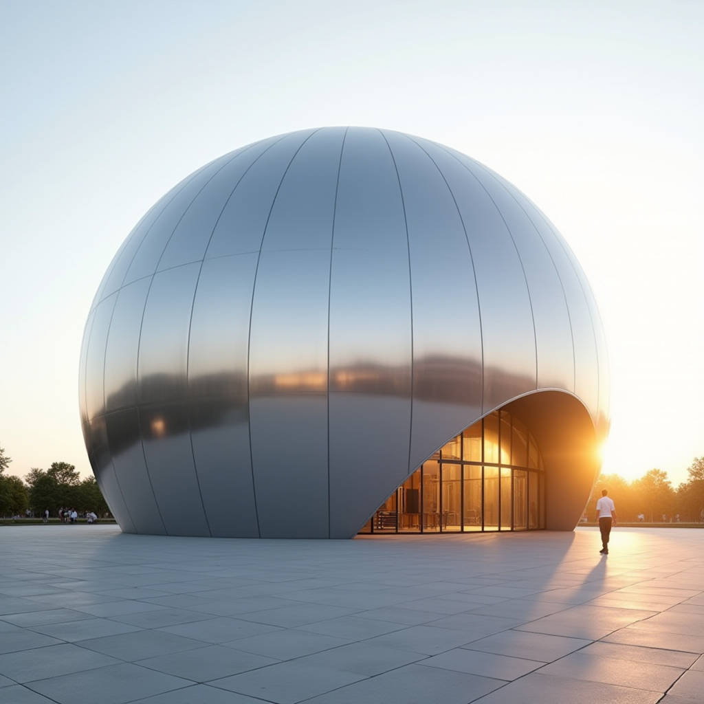
When a design brief calls for a fully spherical or near-spherical aluminum facade, the conversation shifts immediately from standard flat panel procurement to precision engineering. A Spherical Aluminum Facade is not simply a curved rainscreen. It is a compound-curvature envelope where every panel occupies a unique position in three-dimensional space, demanding a fundamentally different approach to design rationalization, fabrication, and installation. As a contractor or facade engineer, you are not just buying panels. You are managing a geometric puzzle where tolerance stacking, thermal movement, and structural load paths intersect at every joint. This article examines the specific engineering challenges that define spherical aluminum cladding projects, from geodesic panelization strategies to wind load distribution on doubly curved surfaces, and provides the technical framework needed to evaluate bids, specify materials, and execute installation without costly field rework.
Why Spherical Geometry Changes Everything
Flat aluminum panels and single-curved (cylindrical) panels share a common trait: they can be unrolled into a flat pattern without distortion. A sphere cannot. This is the fundamental geometric reality that separates a Spherical Aluminum Facade from every other cladding typology. When you attempt to wrap a sphere with rigid sheet material, you must either stretch the material (impossible with solid aluminum) or subdivide the surface into smaller facets that approximate the curvature.
The practical consequence is that every panel on a spherical surface is a double-curved element. Unlike a cylindrical facade where panels can be standardized along the straight axis, a spherical envelope produces zero identical panels. Each piece has a unique Gaussian curvature signature. The procurement team must therefore plan for 100% custom fabrication, which affects lead times, tooling costs, and quality control protocols. A typical mid-sized spherical dome with a 15-meter diameter might require 400 to 600 individually numbered panels, each with its own shop drawing, CNC program, and inspection report.
This also means that the panelization strategy—how you subdivide the sphere into manageable, fabricable pieces—becomes the single most consequential decision in the project. Get it wrong, and you will face visible faceting, uneven joint widths, or panels that simply cannot be installed because accumulated tolerances close the gaps.
Panelization Strategies: Geodesic vs. Meridian-Based Approaches
Two dominant panelization methods exist for spherical aluminum facades. The geodesic approach, popularized by Buckminster Fuller, subdivides the sphere into triangular facets arranged along great-circle arcs. The meridian-based approach divides the sphere into horizontal bands (like latitude lines) and vertical segments (like longitude lines), producing trapezoidal or rectangular panels that narrow toward the poles.
Each strategy carries distinct implications for fabrication complexity and visual appearance. The table below summarizes the key trade-offs that project teams must evaluate before committing to a panelization scheme.
| Parameter | Geodesic Panelization | Meridian-Based Panelization |
|---|---|---|
| Panel Shape Consistency | Triangular panels with varying edge lengths; high geometric diversity | Trapezoidal panels; more uniform within each horizontal band |
| Fabrication Complexity | High — each triangle requires unique tooling and compound-curve forming | Moderate — panels in the same band share similar curvature profiles |
| Visual Faceting | Minimal — triangular facets approximate curvature smoothly | Noticeable at polar regions where panels become narrow wedges |
| Joint Alignment | Complex — three-way joints at every vertex require precise mitering | Simpler — predominantly four-way joints with predictable geometry |
| Material Yield | Lower — triangular nesting on rectangular sheets produces more scrap | Higher — trapezoidal shapes nest efficiently on standard sheet sizes |
| Installation Sequencing | Flexible — can start from multiple points | Sequential — typically bottom-up, band by band |
| Typical Cost Index (Relative) | 1.3 – 1.6x | 1.0x (baseline) |
The meridian-based approach is generally preferred for architectural applications where the sphere is a full or partial dome, because it aligns joint lines with the natural visual grid of the building. However, for standalone spherical structures—planetariums, observatories, or sculptural pavilions—the geodesic approach often delivers a more organic appearance that reads as truly spherical rather than faceted.
Material Selection: Alloy, Temper, and Thickness for Compound Curves
Not all aluminum alloys respond equally well to the compound-curve forming required for spherical panels. The forming process typically involves stretch forming, press braking with custom radius tooling, or multi-point dieless forming. Each method imposes different demands on the material's elongation capacity and springback behavior.
AA3003 H14 is the workhorse alloy for curved aluminum cladding. Its manganese content provides a balanced combination of formability and strength, with an elongation of 8-12% depending on temper. For tighter spherical radii or more aggressive double-curvature requirements, AA5052 H32 offers superior ductility with elongation values of 12-18%, though at a higher material cost. AA1100, while highly formable, lacks the yield strength needed for exterior facade panels that must resist wind loads without excessive deflection.
Panel thickness for spherical applications typically ranges from 2.5mm to 3.0mm. Thinner material (2.0mm) may be viable for small-radius spheres with dense substructure support, but the risk of oil-canning—visible waviness on the panel surface—increases significantly on compound-curved surfaces. The forming process itself can introduce residual stresses that manifest as surface distortion when the panel is subjected to thermal cycling. A 3.0mm panel provides a meaningful safety margin against this phenomenon, particularly on large-format panels exceeding 1.2 meters in any dimension.
For projects requiring both spherical geometry and fire performance, solid aluminum panels with a minimum thickness of 2.5mm meet the non-combustibility requirements of ASTM E136 and EN 13501-1 Class A1, without the complications associated with composite core materials. This is a critical specification point for facade engineers working on high-rise or public assembly buildings where fire codes are stringent.
Wind Load Distribution on Spherical Surfaces
Wind engineering for a Spherical Aluminum Facade differs substantially from flat or prismatic buildings. A sphere presents a continuously varying surface angle to the wind, which means the pressure coefficient changes at every point on the envelope. Unlike a rectangular building where you can define discrete pressure zones for corner, edge, and field areas, a spherical surface requires a more granular analysis.
Per ASCE 7-16 and similar international wind codes, the external pressure coefficient (Cp) on a sphere varies with the angular position relative to the wind direction. At the stagnation point (directly facing the wind), Cp approaches +1.0. As the angle increases to approximately 70 degrees from the stagnation point, the pressure drops to zero and then becomes negative (suction). The maximum suction occurs at roughly 90 degrees, where Cp can reach -1.5 or lower depending on the Reynolds number of the flow.
This distribution creates two practical challenges for panel engineering. First, the fixings and substructure must be designed for both positive pressure and suction, with the suction loads often governing the design of the panel-to-subframe connections. Second, the transition zone between positive and negative pressure can generate oscillating loads under turbulent wind conditions, raising fatigue considerations for the fasteners and aluminum substructure components.
A conservative approach for preliminary design is to use a design wind pressure of 1.5 kPa to 2.5 kPa for mid-rise spherical structures in typical urban environments. However, for exposed coastal sites or tall spherical elements, a wind tunnel study or computational fluid dynamics (CFD) analysis is strongly recommended. The cost of such analysis—typically USD 15,000 to 40,000—is modest compared to the potential liability of under-designed cladding on a landmark spherical structure.
Substructure Design: Accommodating 3D Curvature
The substructure for a spherical aluminum facade must perform two functions that flat-wall systems do not: it must provide a geometrically accurate mounting surface for the curved panels, and it must accommodate differential thermal movement in three dimensions. A conventional vertical rail system designed for planar facades cannot simply be bent to follow a spherical surface without introducing torsion and misalignment at the connections.
The most common solution is a space-frame substructure fabricated from aluminum extrusions or tubular steel sections, with adjustable brackets at each panel connection point. These brackets provide three-axis adjustability (X, Y, Z) to compensate for fabrication tolerances in both the panels and the primary structure. For a 15-meter diameter sphere, the substructure might incorporate 800 to 1,200 individual connection points, each requiring survey verification before and after panel installation.
Thermal movement deserves particular attention. A solid aluminum panel 3.0mm thick with a linear dimension of 1.5 meters will expand approximately 3.5mm across a 100°C temperature range (coefficient of thermal expansion for aluminum: 23.1 × 10⁻⁶ /°C). On a spherical surface, this expansion is not linear—it manifests as a slight change in the panel's curvature. The joint design must accommodate this movement without binding or opening gaps that compromise weather resistance. Open joints with a minimum width of 8-12mm, backed by a continuous EPDM gasket or a secondary weather barrier, are standard practice for spherical cladding systems.
Fabrication Tolerances and Quality Control
The tolerance chain on a spherical aluminum facade is unforgiving. A deviation of 1mm in panel curvature at the fabrication stage, compounded across 30 panels in a meridian line, can produce a 30mm misalignment at the pole. This is not a theoretical concern—it is a documented failure mode on projects where panel inspection was limited to dimensional checks on flat reference surfaces.
Fabrication tolerances for spherical panels should be specified explicitly in the project documentation. The following values represent achievable standards for a competent fabricator using CNC stretch-forming or multi-point forming equipment:
- Panel edge length: ±1.0mm for panels up to 1.5m; ±1.5mm for panels 1.5m to 2.5m
- Curvature deviation (gap under a 300mm radius gauge): ≤0.5mm
- Twist (out-of-plane deviation across diagonals): ≤2.0mm per meter of diagonal length
- Fold angle tolerance (for faceted geodesic panels): ±0.5°
- PVDF coating thickness (AAMA 2605): Minimum 30μm total dry film thickness, measured per ASTM D7091
Quality control should include a 100% dimensional inspection of all spherical panels using a coordinate measuring machine (CMM) or 3D laser scanning. Random sampling is insufficient for spherical geometry because each panel is unique; a defect in one panel cannot be remedied by swapping in a spare from inventory. Some fabricators, including Futeng®, maintain dedicated quality control cells for complex-geometry projects where every panel is scanned and compared against its digital model before shipment. This level of inspection adds cost but is essential for avoiding field modifications that can delay project completion by weeks.
Coating Systems for Three-Dimensional Surfaces
Applying a uniform architectural coating to a compound-curved aluminum panel presents challenges that do not exist on flat surfaces. The electrostatic spray application process relies on a consistent distance between the spray gun and the substrate. On a concave surface, the gun cannot maintain this distance at the center of the panel, leading to variations in film thickness and potential color inconsistency.
For spherical panels, PVDF (polyvinylidene fluoride) coatings based on 70% Kynar 500® or Hylar 5000® resin systems remain the industry standard for exterior durability. The AAMA 2605 specification requires a minimum 20-year performance benchmark for color retention and chalk resistance, which is particularly relevant for spherical structures that are often landmark buildings with extended service life expectations.
Three-coat PVDF systems (primer + color coat + clear coat) provide the best combination of corrosion protection and aesthetic consistency on curved surfaces. The clear coat helps to level out minor variations in the color coat thickness that may occur on complex geometries. For metallic or mica finishes, a four-coat system including a barrier coat may be necessary to prevent orientation-dependent color shift—a phenomenon where metallic flakes align differently on curved versus flat areas, creating visible color variation across the sphere.
Powder coating is technically feasible for spherical panels but is less common in exterior applications due to the challenges of achieving uniform film thickness on compound curves and the limited range of UV-stable chemistries compared to PVDF liquid coatings. Anodizing, while producing a durable and distinctive finish, is generally not recommended for spherical panels because the anodic layer's thickness can vary on curved surfaces, and color matching across a large number of individually processed panels is extremely difficult.
Installation Sequencing and Site Logistics
Installing a Spherical Aluminum Facade is a sequential operation where the order of panel placement directly affects the achievable joint quality. Unlike a flat facade where multiple crews can work simultaneously on different elevations, a spherical surface requires a carefully orchestrated installation sequence that respects the geometric constraints of the structure.
For meridian-based panelization, the standard approach is to install from the equator upward in complete horizontal bands. Each band must be fully installed and surveyed before proceeding to the next, because the lower band provides the reference edge for the band above. Attempting to install panels out of sequence—for example, skipping ahead to the polar region while the equatorial band is incomplete—almost always results in cumulative errors that cannot be corrected without removing and re-installing panels.
Access is another critical consideration. Traditional mast climbers and swing stages are designed for vertical or near-vertical surfaces. On a spherical structure, the working face angles continuously change, and at the upper portions of the sphere, the surface may be overhead. Specialized access solutions—articulating boom lifts, custom-designed ring scaffolds, or modular suspended platforms—must be factored into the installation budget and schedule. The access cost for a spherical facade can be 2 to 3 times that of a comparable flat facade area, and this should be reflected in the contractor's bid.
Survey control during installation requires a minimum of three fixed reference points around the structure, with a total station used to verify the position of each panel's corner points to within ±3mm of the design coordinates. For a 500-panel sphere, this translates to approximately 2,000 individual survey measurements during the installation phase. Laser scanning at key milestones—after substructure completion, after 50% panel installation, and after 100% installation—provides an auditable record of geometric conformance.
Cost Structure and Procurement Realities
Procurement managers approaching a spherical facade project for the first time often underestimate the cost multiplier relative to flat cladding. Based on project data from completed spherical and dome structures, the following cost factors should inform budget planning:
- Engineering and shop drawings: 3-5x the cost of flat panel engineering, due to the need for individual panel drawings and 3D modeling of every component
- Fabrication: 2-4x the per-square-meter cost of flat panels, driven by CNC forming time, custom tooling, and 100% dimensional inspection
- Substructure: 1.5-2.5x the cost of standard rainscreen substructure, reflecting the need for adjustable connections and space-frame geometry
- Installation labor: 2-3x the labor cost of flat panel installation, due to slower production rates and the skill requirements for setting curved panels
- Access and scaffolding: 2-3x the cost for equivalent flat facade area
An all-in installed cost of USD 800 to 1,600 per square meter is a realistic range for a high-quality Spherical Aluminum Facade with PVDF finish, depending on the sphere diameter, panelization complexity, and site conditions. Smaller spheres (under 10m diameter) trend toward the upper end of this range because the fixed costs of engineering and setup are amortized over a smaller area.
Lead times for spherical panels typically run 14 to 20 weeks from approved shop drawings to delivery, compared to 8 to 12 weeks for standard flat panels. This extended timeline must be integrated into the overall construction schedule, particularly if the spherical element is on the critical path. Early engagement with the facade fabricator—ideally during the design development phase—can compress the overall timeline by allowing shop drawing preparation to proceed in parallel with structural design finalization.
Specifying a Spherical Aluminum Facade: Key Contract Clauses
A well-drafted specification is the first line of defense against disputes and quality failures on spherical facade projects. Beyond the standard requirements for material grade, coating performance, and structural performance, the following clauses should be included in any specification for spherical aluminum cladding:
- Panelization responsibility: Clearly assign responsibility for the panelization design to either the architect of record, the facade engineer, or the fabricator. Ambiguity on this point leads to delays and finger-pointing when panelization issues arise.
- Mock-up requirements: Require a physical mock-up of at least 3x3 panels (9 panels minimum) at a representative curvature zone, installed on the actual substructure system, with the specified coating and joint treatment. The mock-up must be approved before production panels are fabricated.
- Dimensional verification protocol: Specify the measurement method (CMM or 3D laser scan), the acceptance criteria, and the documentation format for panel dimensional inspection.
- Thermal movement accommodation: Require the system designer to submit calculations demonstrating that the joint design accommodates the full design temperature range without binding or exceeding gasket compression limits.
- Weather performance testing: Reference ASTM E283 (air infiltration), ASTM E331 (water penetration under static pressure), and ASTM E330 (structural performance under uniform static air pressure) for the complete system assembly, tested on the approved mock-up.
For projects in seismic zones, additional testing per AAMA 501.4 (recommended static test method for evaluating curtain wall and storefront systems subjected to seismic and wind-induced inter-story drift) should be considered, as spherical structures can exhibit complex dynamic responses during seismic events.
Digital Workflow: From Rhino to Reality
The technical execution of a Spherical Aluminum Facade depends heavily on the digital design-to-fabrication workflow. The typical toolchain begins with a parametric model in Rhino with Grasshopper, where the sphere is panelized and each panel is assigned a unique identifier. This model drives the generation of individual panel fabrication drawings, CNC forming programs, and the coordinate data for on-site survey control.
The critical step that separates successful projects from troubled ones is the bidirectional data flow between the design model and the fabrication output. The fabricator must be able to receive the architect's panel geometry, apply manufacturing constraints (minimum bend radius, springback compensation, edge return dimensions), and return the as-fabricated geometry to the design team for clash detection and joint width verification. This iterative process, often called the "design-assist" phase, requires close collaboration between the architect, facade engineer, and fabricator over a period of 6 to 10 weeks.
Building Information Modeling (BIM) coordination should include the spherical facade at LOD 400 (fabrication-ready level of development), with each panel represented as an individual element carrying its material properties, finish specification, and installation sequence number. This level of detail supports automated clash detection with the primary structure and MEP penetrations, reducing the risk of field conflicts that are disproportionately expensive to resolve on curved surfaces.
A spherical facade is not a product you buy from a catalog. It is an engineered system where geometry, material science, and construction methodology converge. The projects that succeed are those where the contractor treats the facade not as a subcontract line item but as a collaborative engineering endeavor from day one.
For project teams evaluating fabricator capabilities for spherical aluminum cladding, the key questions to ask are not about price per square meter. They are about the fabricator's experience with compound-curve geometry, the capacity of their CNC forming equipment, their dimensional inspection protocol, and their track record of delivering projects where every panel is unique. A fabricator that has successfully delivered multiple spherical or high-curvature projects brings institutional knowledge that cannot be replaced by a lower bid. The cost of a failed spherical facade—in rework, schedule delay, and reputational damage—dwarfs any savings from choosing a fabricator without the relevant experience.