Hyperbolic Aluminum Facade Engineering From CNC Forming to Weatherproof Installation
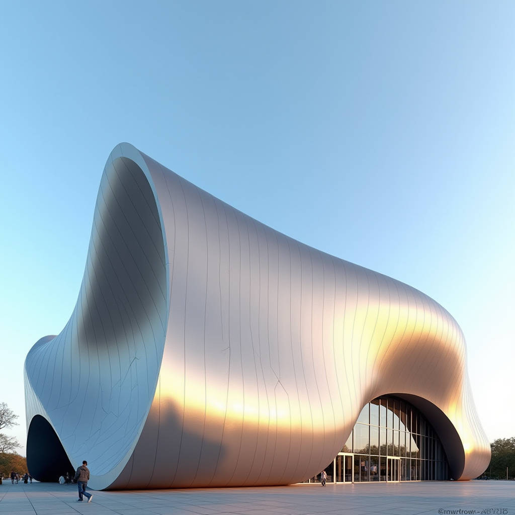
Getting the geometry right on a hyperbolic aluminum facade separates projects that win industry awards from those that rack up change orders for years after handover. A hyperbolic paraboloid surface curves in two opposing directions simultaneously. Every panel in the system carries a unique Gaussian curvature profile. When the engineering team misunderstands how that curvature translates into fabrication tolerances, the result is onsite rework, water ingress, and an installation crew that loses confidence in the material. This article examines the specific relationship between double-curvature geometry, CNC forming accuracy, and long-term weatherproofing performance in solid aluminum hyperbolic cladding systems. We focus on what procurement managers and facade engineers need to verify before signing off on shop drawings for a hyperbolic aluminum facade.
What Defines a True Hyperbolic Aluminum Facade Panel
A hyperbolic panel is not simply a curved sheet. The geometry requires that the surface curves upward along one axis and downward along the perpendicular axis at every point. This double curvature means the panel cannot be unrolled into a flat rectangle without distortion. In architectural terms, the surface has negative Gaussian curvature. Manufacturing such panels demands multi-axis CNC forming equipment that can stretch and compress aluminum sheet simultaneously across different zones. Standard press brakes cannot produce true hyperbolic surfaces. The distinction matters because some suppliers market single-curved or conical panels as "hyperbolic" to win specifications. A single-curved panel bends along one axis only. A conical panel has zero Gaussian curvature. Neither performs the same structural or visual function as a genuine hyperbolic aluminum facade element.
The material starting point is solid aluminum alloy sheet, typically grade AA3003, AA5052, or AA1100, with thickness ranging from 2.0mm to 3.0mm for exterior facade applications. Thinner gauges below 2.0mm introduce oil-canning risk on double-curved surfaces. The forming process involves CNC-controlled stretch forming or multi-point die forming, where an array of adjustable pins creates the precise negative mold. After forming, each panel undergoes dimensional verification against the 3D model using laser scanning or coordinate measuring equipment. Tolerance expectations for hyperbolic panels should be tighter than flat panels because curvature amplifies alignment errors at panel joints. Industry practice targets ±1.5mm across the panel surface and ±2.0mm at edges, though project-specific requirements may tighten these further.
CNC Forming Technology and Its Impact on Panel Accuracy
The core manufacturing challenge in hyperbolic aluminum facade production is translating a digital twin into physical metal without springback distortion. Aluminum alloy exhibits elastic recovery after forming. The amount of springback depends on alloy grade, temper, sheet thickness, and the radius of curvature. AA3003-H14, a common choice for architectural cladding, has different springback behavior than AA5052-H32. Fabricators compensate by over-forming the panel beyond the target geometry, anticipating that the material will relax back to the design intent. This compensation factor is developed through empirical testing on each alloy batch and stored in the CNC machine's control parameters.
Multi-point stretch forming machines use hydraulic or servo-driven grippers that clamp the sheet perimeter and pull it over a die. The die itself may be reconfigurable, with adjustable pin matrices that can be reprogrammed for each unique panel shape. For a large hyperbolic aluminum facade project with hundreds of panels, no two panels share identical geometry. The CNC program for each panel is generated directly from the architect's parametric model, typically exported from Rhino with Grasshopper or similar software. The digital workflow eliminates manual pattern-making and reduces cumulative error. However, the quality of the output depends on how well the fabricator's post-processor interprets the surface data. Dense mesh data with high point counts produces smoother toolpaths than simplified geometry.
After forming, panels undergo trimming on 5-axis CNC routers that cut the perimeter to final dimensions and create any openings, returns, or folded edges. The 5-axis capability allows the cutting tool to remain normal to the curved surface, producing clean edges without undercutting. This step is critical for joint alignment because even a 1mm deviation at a panel edge becomes visible when two hyperbolic panels meet along a curved seam.
Surface Treatment and Coating Durability on Curved Substrates
Applying architectural coatings to a hyperbolic aluminum facade panel introduces challenges that flat panels do not face. The curvature causes variation in spray distance, angle, and film thickness across the surface. PVDF fluoropolymer coatings, the industry standard for exterior aluminum cladding, require a minimum dry film thickness of 25-30 microns for the color coat and 5-10 microns for the clear coat, per AAMA 2605 specifications. On a hyperbolic surface, the spray operator must adjust gun angle and distance dynamically to maintain uniform coverage. Automated robotic spray systems with 6-axis arms programmed from the same 3D model as the forming process deliver more consistent results than manual spraying.
Coating adhesion on curved aluminum is tested using the same ASTM D3359 cross-hatch method as flat panels, but the curved geometry makes it harder to achieve uniform tape contact during testing. Qualified fabricators perform adhesion tests on curved witness samples produced alongside production panels. The PVDF coating system, typically based on Kynar 500® or Hylar 5000® resin, provides documented resistance to UV degradation, chalking, and color fade over 20-plus years of exterior exposure. For coastal or high-pollution environments, some projects specify a three-coat system with a corrosion-inhibiting primer beneath the color and clear coats.
| Coating System | Resin Base | DFT (microns) | Gloss Retention (10yr) | Applicable Standard | Best Suited Environment |
|---|---|---|---|---|---|
| PVDF 2-Coat | Kynar 500® / Hylar 5000® | 30-35 | ≥50% at 60° | AAMA 2605 | General urban exterior |
| PVDF 3-Coat | Kynar 500® / Hylar 5000® | 40-50 | ≥65% at 60° | AAMA 2605 | Coastal, industrial, high-UV |
| FEVE Fluoropolymer | Lumiflon® FEVE | 30-40 | ≥70% at 60° | AAMA 2605 | Extreme UV, tropical |
| Polyester (PE) | Polyester resin | 25-30 | ≤30% at 60° | AAMA 2603 | Interior, sheltered exterior |
| Powder Coating | Polyester / Super Durable | 60-80 | ≥50% at 60° | Qualicoat Class 2 | Interior, moderate exterior |
Structural Engineering Considerations for Hyperbolic Cladding
A hyperbolic aluminum facade panel behaves differently under wind load than a flat panel of the same thickness. The double curvature introduces geometric stiffness. A hyperbolic paraboloid shape resists deflection through membrane action, distributing stress across the surface rather than concentrating it at bending points. This means a 2.5mm thick hyperbolic panel can often span greater distances between support points than a flat 3.0mm panel, provided the curvature depth is sufficient. However, this benefit only materializes when the curvature is genuine. Shallow hyperbolic surfaces with minimal depth-to-span ratios behave more like flat plates and lose the structural advantage.
Wind load calculations for hyperbolic aluminum facade systems should follow the project's governing code, typically ASCE 7 in North America, EN 1991-1-4 in Europe, or the local national standard. The pressure coefficients for curved surfaces differ from those for flat walls. A hyperbolic surface may experience both positive and negative pressures across different zones under the same wind direction. Computational fluid dynamics modeling is recommended for complex geometries, especially on buildings over 50 meters in height where wind tunnel effects between adjacent structures become significant.
The subframe that supports the hyperbolic panels must accommodate three-dimensional adjustment. Unlike flat panel systems where shims and slotted holes provide sufficient adjustment in two axes, hyperbolic systems require adjustment in all three axes plus rotational freedom. Proprietary bracket systems with spherical washers, slotted connections, and adjustable standoffs are commonly used. The subframe material is typically aluminum extrusion or stainless steel, selected to match the thermal expansion coefficient of the cladding panels and avoid galvanic corrosion. Isolation between aluminum panels and steel substructure using EPDM or neoprene gaskets is mandatory.
Waterproofing and Joint Design for Double-Curved Facades
Water management on a hyperbolic aluminum facade demands more rigorous joint design than on planar facades. The curvature creates gravity-driven water flow paths that change direction across the surface. A joint that sheds water effectively at one elevation may collect water at another. The standard approach uses a pressure-equalized rainscreen principle, where the outer panel joints are open to allow air pressure equalization, and a continuous air and water barrier behind the cladding handles any moisture that penetrates the outer layer.
Open joints between hyperbolic panels typically range from 12mm to 20mm in width, depending on the panel size and curvature radius. The joint width must remain visually consistent despite the changing geometry. This requires the panel edges to be trimmed with variable offsets during CNC machining so that the installed gap appears uniform. Behind the open joint, a dark-colored EPDM or silicone gasket with a labyrinth profile prevents direct water entry while allowing air movement. The gasket material must maintain flexibility at the project's design temperature extremes, typically -30°C to +80°C for most regions.
At panel corners where three or more hyperbolic panels meet, the joint geometry becomes particularly complex. The intersection of curved edges creates a three-dimensional void that must be detailed carefully. Prefabricated corner boots made from molded EPDM or formed aluminum with welded seams provide a reliable solution. Field-fabricated corner seals using wet sealant are less reliable on curved surfaces because tooling the sealant to a consistent profile is difficult when the substrate curves in two directions.
Installation Methodology and Tolerance Stack-Up
Installing a hyperbolic aluminum facade requires a fundamentally different sequence than flat panel installation. The installation team cannot rely on a fixed grid or repeating module. Every panel has a unique position in the overall geometry, and installing a panel out of sequence can propagate errors that become impossible to correct later. The recommended approach is to establish primary control points at the building corners and major geometric inflection points, then work inward toward the centers of each hyperbolic surface.
Laser scanning during installation provides real-time verification that the installed panels match the design model. A total station or 3D laser scanner captures the position of each panel after mounting, and the data is compared against the BIM model. Deviations exceeding the specified tolerance trigger immediate correction before the next panel is installed. This workflow, sometimes called "scan-to-BIM verification," prevents the accumulation of tolerance errors that can result in a 20mm misalignment by the time the last panel in a sequence is reached.
The bracket system must allow for differential thermal movement between the aluminum panels and the building structure. Aluminum expands at approximately 0.024mm per meter per degree Celsius. A 3-meter hyperbolic panel subjected to a 60°C temperature swing will change length by about 4.3mm. Fixed points should be located at the panel centroid or at one edge, with sliding connections elsewhere that permit movement without binding. The sliding connections must remain functional over the building's service life, so stainless steel components with PTFE bearing pads are preferred over galvanized steel that may corrode and seize.
Cost Drivers and Procurement Strategy
The cost of a hyperbolic aluminum facade system is driven primarily by four factors: panel quantity and uniqueness, curvature complexity, coating specification, and logistics. Because each panel is geometrically unique, there is no economy of scale in the traditional sense. However, fabrication efficiency improves when panels share similar curvature radii, even if their overall shapes differ. Grouping panels by curvature class during production scheduling reduces CNC setup time and material waste.
Material yield from flat sheet to finished hyperbolic panel typically ranges from 65% to 80%, compared to 85% to 95% for flat panels. The lower yield results from the perimeter trimming required after forming and the fact that the blank sheet must be larger than the finished panel to provide gripping margins for the stretch-forming machine. Procurement managers should budget for 20-35% material waste when estimating raw aluminum costs for a hyperbolic aluminum facade.
Shipping hyperbolic panels presents another cost consideration. Unlike flat panels that stack efficiently in crates, hyperbolic panels require custom dunnage that supports each panel's unique shape without imposing loads that could cause deformation. A 40-foot container that holds 800-1,000 square meters of flat panels may only hold 400-500 square meters of hyperbolic panels. This effectively doubles the per-square-meter shipping cost. For projects in North America or Europe sourcing from Asian manufacturers, the logistics cost can represent 8-12% of the total facade package value.
Lead times for hyperbolic aluminum facade systems typically range from 12 to 20 weeks from approved shop drawings to delivery, depending on project size and complexity. The shop drawing phase itself requires 4-8 weeks because each panel must be detailed individually. Projects that engage the facade fabricator early, during the design development phase rather than after tender, can compress the overall schedule by overlapping shop drawing development with the architect's design finalization. Suppliers such as Futeng® with in-house engineering teams and dedicated hyperbolic production lines can offer more predictable lead times than fabricators who subcontract the CNC forming work.
Quality Verification and Factory Inspection Protocol
Given the complexity of hyperbolic aluminum facade panels, third-party factory inspection is strongly recommended. The inspection protocol should verify dimensional accuracy, coating quality, and structural integrity before panels are packed for shipment. Key inspection points include:
- Dimensional verification of each panel against the 3D model using a calibrated coordinate measuring machine or laser tracker, with a tolerance of ±1.5mm on surface profile and ±2.0mm on edge position.
- Coating thickness measurement using a calibrated eddy-current gauge, with readings taken at a minimum of five points per panel surface, including areas of maximum curvature where thickness variation is most likely.
- Gloss measurement at 60° geometry per ASTM D523, with values compared to the approved control sample.
- Adhesion testing per ASTM D3359 Method B on a retained witness panel from the same production batch.
- Visual inspection under controlled lighting for surface defects including orange peel, dirt inclusion, and color variation.
Documentation from the factory should include mill test certificates for the aluminum coil, coating batch certificates, dimensional inspection reports, and a certificate of conformance referencing the applicable standards. For projects requiring AAMA 2605 compliance, the coating applicator must be licensed by the resin manufacturer, and the license should be verified independently.
Fire Performance and Code Compliance
Solid aluminum hyperbolic facade panels are inherently non-combustible. Aluminum alloy does not burn, and the PVDF coating, while organic, is applied in such thin films that its contribution to fire load is negligible. In European classification under EN 13501-1, a solid aluminum panel with PVDF coating typically achieves A2-s1,d0, the highest rating achievable for a metal composite system. The "s1" indicates minimal smoke production, and "d0" indicates no flaming droplets. This classification satisfies the fire safety requirements for buildings over 18 meters in height in the UK and similar jurisdictions that have tightened cladding regulations following the Grenfell Tower fire.
In North America, solid aluminum panels are tested to ASTM E84 (surface burning characteristics) and typically achieve a Class A rating with a flame spread index of 0-25 and smoke developed index of 0-50. The NFPA 285 test for exterior wall assemblies evaluates the full wall system including insulation, air barrier, and cladding. Solid aluminum panels with non-combustible insulation and proper fire stopping details routinely pass NFPA 285. Procurement specifications should require the panel supplier to provide independent test reports, not just a letter of compliance, for any project where fire performance is a regulatory concern.
For a deeper understanding of fire testing requirements for exterior cladding, refer to the NFPA 285 standard and the AAMA guidelines for metal curtain wall systems. The ISO 21927 series also provides international guidance on smoke and heat control systems relevant to facade design.
Digital Workflow Integration from Design to Fabrication
The success of a hyperbolic aluminum facade project depends heavily on the integrity of the digital data chain. The architect's conceptual model, typically created in Rhino with Grasshopper parametric scripting, must translate into fabrication-ready geometry without data loss or simplification. The key vulnerability in this workflow is the exchange format. STEP and IGES formats preserve surface data as mathematical NURBS definitions, while mesh formats like STL approximate surfaces with triangular facets. For hyperbolic surfaces, mesh approximation introduces faceting that becomes visible in the finished panels if the mesh resolution is too low.
The recommended workflow uses native file exchange in Rhino .3dm format where possible, or STEP AP242 for vendor-neutral exchange. The fabricator's engineering team should receive the architect's surface model and develop it into panelized geometry with joint offsets, edge returns, and attachment points. This developed model becomes the single source of truth for CNC forming, trimming, and quality inspection. Any design change after panelization has begun must be tracked rigorously, because a change to the global surface geometry can cascade into changes across dozens or hundreds of individual panels.
Building Information Modeling coordination adds another layer of value. The hyperbolic aluminum facade model should be integrated with the structural model to verify that attachment points align with the building's primary structure. Clash detection between the facade subframe and other building systems—HVAC louvers, lighting, signage—prevents expensive field modifications. The buildingSMART IFC standard provides a framework for this multi-discipline coordination, though the quality of IFC export from different software platforms varies and should be verified on each project.
Long-Term Maintenance and Service Life Expectations
A properly specified and installed hyperbolic aluminum facade should deliver a service life of 40-50 years before major refurbishment, with the PVDF coating retaining acceptable appearance for 25-30 years depending on environmental exposure. Maintenance requirements are minimal compared to other cladding materials. Annual inspection of joints and sealants, cleaning with mild detergent and water at 2-3 year intervals, and recoating after 25-30 years constitute the typical maintenance program.
Cleaning hyperbolic surfaces requires more care than flat facades. The curvature means that access equipment must be positioned to reach all areas without imposing loads on the panels. Rope access technicians need training on the specific geometry to avoid concentrating body weight on panel edges. Building maintenance unit systems should be designed with the hyperbolic geometry in mind, with cradle arms that can articulate to follow the curved facade profile.
The recoating decision point typically arrives when the original PVDF coating shows chalk rating below 6 per ASTM D4214 or when color change exceeds 5 Delta E units. Recoating hyperbolic panels in situ is more challenging than flat panels because achieving uniform film thickness on curved surfaces requires skilled applicators. Some building owners opt to replace rather than recoat panels at this stage, particularly if the original fabricator can reproduce the panels from archived digital models. Maintaining complete digital records of the panel geometry from the original project is therefore a valuable long-term asset.
For projects seeking LEED certification, solid aluminum hyperbolic panels contribute to credits in the Materials and Resources category. Aluminum is infinitely recyclable without loss of properties, and the recycled content of architectural aluminum sheet typically ranges from 30% to 70% depending on the mill source. The USGBC LEED v4.1 framework recognizes both recycled content and material ingredient reporting. Specifying aluminum from mills that provide Environmental Product Declarations supports the project's sustainability documentation.
Engineering a hyperbolic aluminum facade rewards attention to detail at every stage: geometry definition, CNC forming accuracy, coating uniformity, joint waterproofing, and installation sequencing. The projects that succeed are those where the architect, facade engineer, fabricator, and installer collaborate from schematic design onward, sharing a common digital model and a clear understanding of tolerance expectations. When the procurement team treats hyperbolic panels as a commodity and awards the contract on price alone, the result is almost always a facade that falls short of the design vision. The premium paid for a fabricator with proven hyperbolic experience and robust quality systems is a fraction of the cost of remediating a failed installation.