3D Aluminum Panel Engineering and Fabrication Guide for Commercial Facade Systems
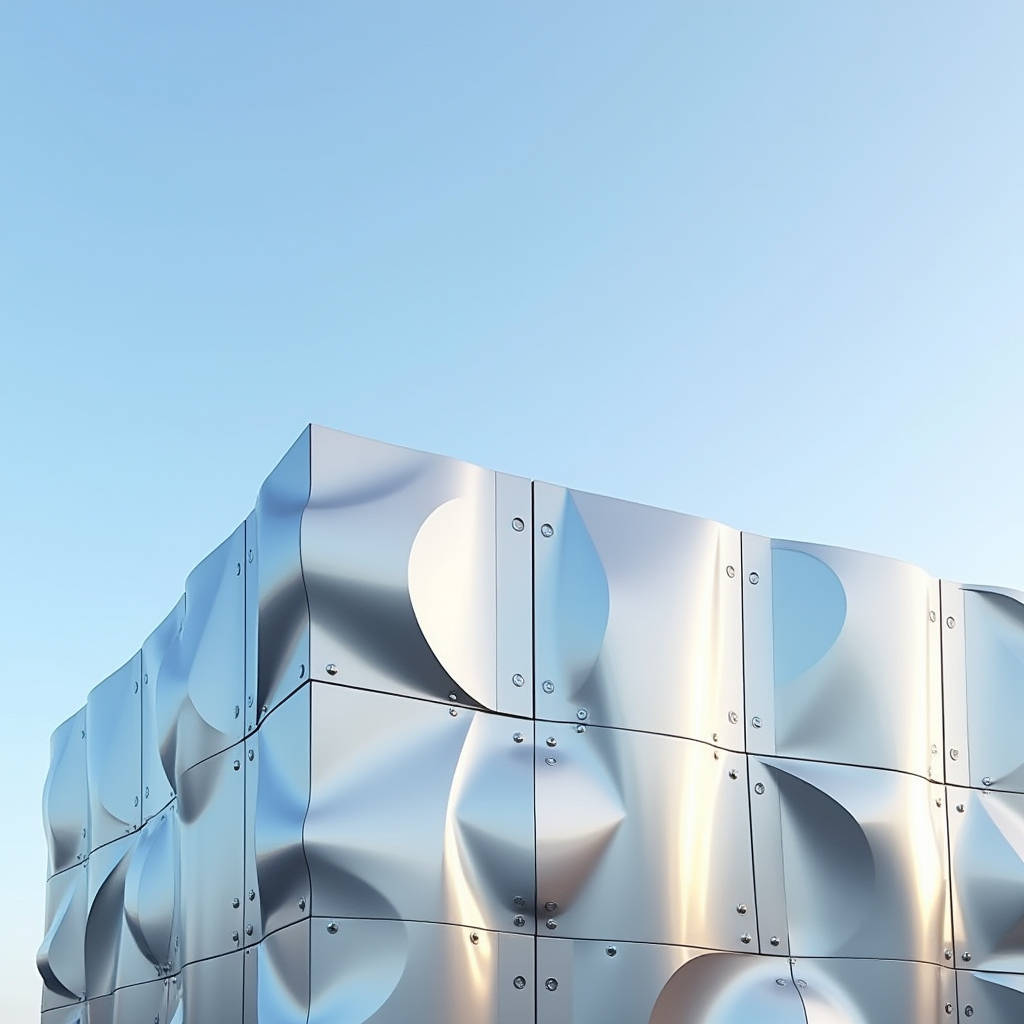
When a flat facade fails to communicate the architectural ambition behind a project, design teams turn to three-dimensional cladding solutions. A 3D Aluminum Panel is a solid aluminum sheet engineered with folded returns, perforated geometries, or pressed relief patterns that project depth beyond the base plane of a building envelope. Unlike flat ACM sheets that rely on printed graphics to simulate texture, solid 3D aluminum panels deliver physical dimensionality through CNC folding, stamping, or welding processes performed on 2.0mm to 3.0mm thick aluminum alloy substrates. The result is a facade system that interacts with daylight dynamically, casting moving shadows across the day and giving the building a sculptural presence that reads differently from every vantage point. For general contractors and facade engineers evaluating options for commercial towers, cultural institutions, and transit hubs, understanding how these panels are fabricated, finished, and installed determines whether the design intent survives the value-engineering process intact.
What Defines a Solid 3D Aluminum Panel
The term "3D" in aluminum cladding gets applied loosely across the market. Some suppliers use it to describe flat composite panels with digital print textures that simulate depth. A genuine 3D Aluminum Panel fabricated from solid aluminum plate achieves its dimensionality through physical deformation of the metal itself. The panel starts as a flat sheet of 5052 or 3003 aluminum alloy, typically 2.0mm, 2.5mm, or 3.0mm thick depending on the span and wind load requirements of the project. CNC press brakes fold the perimeter returns from the same parent sheet, creating a monolithic tray with no separate edge pieces to delaminate or rattle. For more complex geometries, stamping dies press pyramids, waves, or custom relief patterns into the face. Fully mitered and welded corners are ground smooth, producing a seamless appearance that reads as a single sculptural object rather than an assembly of parts.
The structural integrity of this approach matters in high-traffic environments. A solid 3.0mm aluminum panel resists denting and puncturing far better than a 4mm composite panel with a 0.5mm aluminum skin bonded to a polyethylene core. Airport terminals, subway stations, and school buildings subject cladding to luggage impacts, vandalism, and maintenance equipment collisions. In these conditions, the monolithic nature of solid aluminum eliminates the risk of skin delamination that plagues composite products after years of thermal cycling and moisture exposure.
Fabrication Methods That Produce Genuine Depth
Three primary fabrication routes produce the dimensional effects that architects specify. Each carries different cost implications, lead times, and geometric constraints that procurement teams must reconcile with the project budget and schedule.
CNC Folding and Bending
The most economical approach uses CNC press brakes to fold panel edges into returns, creating a tray-like geometry that stands off the substrate by 50mm to 200mm. Multiple panels can be arranged in alternating depths across the facade grid, producing a stepped or faceted surface. The folded return serves a dual purpose: it creates the visual depth and provides the attachment flange for the concealed clip system. Panel sizes up to 1,500mm x 4,000mm can be folded from a single sheet, though the practical limit depends on the press brake bed length available at the fabrication facility. Futeng® operates CNC folding lines capable of handling these dimensions for large-scale commercial projects.
Stamping and Press Forming
For repeating geometric patterns like pyramids, hexagons, or wave profiles, hydraulic stamping presses deform the aluminum sheet into a die set. This method produces highly consistent relief across hundreds of identical panels, making it suitable for modular facade systems where visual uniformity is critical. The stamping process work-hardens the aluminum, slightly increasing surface hardness. However, the depth of relief is limited by the material's elongation properties. 5052 alloy, with approximately 12-18% elongation depending on temper, can typically accommodate relief depths up to 25mm without cracking. Deeper draws require annealing or switching to 3003 alloy with higher elongation.
Welded Assembly and Custom Sculptural Forms
When the design demands compound curves, sharp angles, or geometries that exceed the limits of folding and stamping, fabricators turn to cut-and-weld construction. Individual aluminum plates are cut on 5-axis waterjet or laser machines, then TIG welded together along the seams. The welds are ground flush and the entire assembly is sanded to create an invisible joint. This method is labor-intensive and costs 3-5 times more per square meter than folded panels, but it is the only way to achieve truly sculptural forms like the faceted canopies seen on signature cultural buildings. Lead times for welded assemblies run 8-14 weeks versus 4-6 weeks for folded panels.
Material Specifications and Alloy Selection
Solid aluminum cladding panels are typically specified in 5052-H32 or 3003-H14 alloy. The choice between them involves trade-offs between strength, formability, and cost.
| Property | 5052-H32 | 3003-H14 | Relevance to 3D Panels |
|---|---|---|---|
| Tensile Strength (MPa) | 210-260 | 140-180 | Higher strength allows thinner gauge for same span |
| Yield Strength (MPa) | 160 | 115 | Affects resistance to wind load deflection |
| Elongation (%) | 12-18 | 14-20 | Higher elongation permits deeper stamping depths |
| Corrosion Resistance | Excellent (marine grade) | Good | 5052 preferred for coastal and high-humidity zones |
| Cost Index (relative) | 1.0 | 0.85-0.90 | 3003 offers savings where marine exposure is absent |
| Weldability | Good | Excellent | 3003 preferred for complex welded assemblies |
For most exterior applications on commercial buildings, 5052-H32 is the default specification. Its higher yield strength means a 2.5mm panel can span the same distance as a 3.0mm 3003 panel, reducing weight and material cost. The magnesium content in 5052 provides superior resistance to salt spray, which matters for projects within 5km of coastlines. However, when the design calls for deep stamping with relief exceeding 20mm, 3003-H14 becomes the practical choice because its higher elongation prevents cracking at the deformation points.
Panel thickness is not a cosmetic decision. The AAMA 508 standard for aluminum curtain wall panels references deflection limits of L/175 for panel faces under design wind load. A 2.0mm panel spanning 1,200mm between stiffeners will deflect more than a 3.0mm panel under the same load. For 3D panels with folded returns, the return itself acts as a stiffening rib, potentially allowing a thinner face gauge. Each project requires a structural calculation that accounts for the specific geometry, building height, and local wind speed data per ASCE 7.
Finish Systems and Weathering Performance
The coating system on a 3D Aluminum Panel must perform on surfaces that are not flat. Shadow zones inside recesses, sharp edges on folded corners, and the interior of perforations all present challenges that flat panel coatings do not face. PVDF fluoropolymer coatings based on Kynar 500 or Hylar 5000 resin are the industry standard for exterior architectural aluminum. The specification calls for a three-coat system: a chrome-based conversion coating for corrosion protection, a primer coat (5-8 microns), and a color coat (25-30 microns) for a total dry film thickness of 30-38 microns.
On 3D geometries, spray application must achieve uniform coverage across surfaces oriented at different angles to the spray gun. Recessed areas of stamped patterns can receive less coating thickness if the spray angle is not carefully controlled. Fabricators with experience in 3D panel finishing use robotic spray systems programmed to the specific panel geometry, or manual spray operators who rotate the panel through multiple orientations during application. The American Architectural Manufacturers Association publishes test methods in AAMA 2605 that specify minimum performance for PVDF coatings, including 4,000 hours of salt spray resistance and 10-year Florida exposure with no more than 5 Delta E color change.
For interior applications where UV resistance is not a concern, polyester powder coating offers a cost-effective alternative at roughly 40% less than PVDF. The powder coating process electrostatically applies dry powder that melts and cures into a uniform film, typically 60-80 microns thick. This heavier coating can help mask minor surface imperfections on welded assemblies.
Wind Load Considerations for Projecting Geometries
A 3D panel that projects 100mm from the facade plane experiences different wind pressure than a flush panel. The projecting geometry creates positive pressure on the windward face and negative pressure (suction) on the leeward face and sides. This pressure differential generates a net force that is higher than what a flat panel in the same location would experience. The ASCE 7 standard provides pressure coefficients for various building geometries, but highly irregular 3D facades often fall outside the standard shapes covered in the code.
When standard coefficients do not apply, the project team has two options. The conservative approach applies the highest relevant coefficient from ASCE 7, which may overestimate loads and drive up panel thickness and substructure cost. The more precise approach commissions a wind tunnel study with a scale model of the building that includes the 3D facade geometry. Pressure taps on the model measure actual pressure distributions, providing data for a rational structural design. Wind tunnel studies typically cost $30,000-$80,000 and add 4-6 weeks to the design schedule, but the savings in aluminum and substructure steel can offset this cost on large projects.
The attachment system must also resist the additional moment generated by the panel's projection. A panel standing 150mm off the substructure applies a lever arm to the anchor point. The fastener, clip, and substructure all see higher bending stresses than they would with a flush panel. Stainless steel anchors with a minimum of 316 grade become necessary in corrosive environments, and the embedment depth in concrete or the weld size on steel substructure must be verified by calculation.
Installation Systems and Tolerance Management
Installing 3D Aluminum Panel systems demands tighter tolerance control than flat panel facades. When panels project at different depths, a 5mm deviation in the mounting plane creates a visible misalignment that reads as a shadow line discontinuity. The substructure must be surveyed and adjusted to a tolerance of ±2mm across the entire facade area before panel installation begins.
Concealed clip systems are the dominant attachment method for 3D panels because they eliminate visible fasteners that would disrupt the sculptural appearance. The clip engages a folded return on the back of the panel and is secured to the aluminum or steel substructure. Vertical and horizontal adjustment capability in the clip allows the installer to fine-tune panel position. For panels with deep projections, anti-wind clips or secondary restraints prevent the panel from lifting off the primary clip under negative wind pressure.
Panel joint width deserves careful attention on 3D facades. A 15mm open joint that looks consistent on a flat wall becomes visually irregular when panels step in and out of plane. The specifier should consider whether the joint is measured along the panel face or in the projection plane. Shadow gaps, where the joint is recessed behind the panel face, can mask minor width variations by hiding the joint in shadow. This technique is particularly effective on south-facing facades where direct sunlight would otherwise highlight every installation irregularity.
Cost Structure and Budget Planning
The installed cost of a 3D aluminum panel facade varies widely based on panel complexity, finish, and project location. The following table provides indicative ranges based on 2024-2025 project data for commercial buildings in North American and European markets.
| Cost Component | Folded 3D Panel (simple geometry) | Stamped 3D Panel (patterned) | Welded Custom 3D Panel |
|---|---|---|---|
| Material (aluminum sheet) | $18-25/m² | $18-25/m² | $22-30/m² |
| Fabrication labor | $35-50/m² | $55-80/m² | $120-180/m² |
| PVDF coating (3-coat) | $25-35/m² | $30-40/m² | $35-45/m² |
| Substructure and clips | $40-60/m² | $45-65/m² | $50-75/m² |
| Installation labor | $50-70/m² | $60-85/m² | $80-120/m² |
| Engineering and shop drawings | $8-12/m² | $10-15/m² | $15-25/m² |
| Total installed (approximate) | $176-252/m² | $218-310/m² | $322-475/m² |
These figures assume a minimum project size of 500m². Smaller projects will see higher per-square-meter costs due to fabrication setup charges and mobilization inefficiencies. The cost premium for 3D panels over flat panels of the same material and finish ranges from 30% for simple folded geometries to 150% for complex welded assemblies. Value engineering efforts typically focus on reducing the number of unique panel geometries, standardizing projection depths, and limiting the use of welded construction to high-visibility areas only.
Quality Control and Factory Inspection Protocols
Before panels ship from the fabrication facility, a structured inspection process should verify conformance to the approved shop drawings and finish specifications. For 3D panels, dimensional inspection is more involved than for flat panels because the projection depth and angle must be measured at multiple points. A coordinate measuring machine or a calibrated jig can verify that the as-built geometry matches the CAD model within the agreed tolerance, typically ±1.5mm for folded panels and ±3mm for welded assemblies.
Coating inspection follows ASTM D7091 for dry film thickness measurement and ASTM D3359 for adhesion testing. The inspector should pay particular attention to sharp edges and inside corners on 3D panels, as these areas are prone to thin coating coverage. A minimum of 25 microns of PVDF color coat should be maintained even on edges, which may require the fabricator to apply a stripe coat to edges before the full spray application.
Third-party inspection by an accredited laboratory adds credibility to the quality assurance process. For projects requiring LEED certification or similar green building credentials, the inspector can also verify that the aluminum content includes the specified recycled percentage and that the coating meets VOC limits per the applicable regional regulation.
Supply Chain and Lead Time Management
The procurement timeline for a custom 3D Aluminum Panel package runs longer than for standard flat panels. The critical path typically runs through the following stages: design finalization and shop drawing approval (3-4 weeks), material procurement (2-4 weeks depending on alloy and thickness availability), fabrication (4-8 weeks depending on complexity), finishing (2-3 weeks including curing), and shipping (1-4 weeks depending on origin and destination). A realistic total lead time is 12-16 weeks from approved shop drawings to delivery on site.
Projects in North America and Europe increasingly source 3D panels from manufacturers in Asia, where fabrication labor costs are lower. However, the shipping cost and time must be weighed against local fabrication. A 40-foot container can hold approximately 800-1,200m² of 3D panels depending on the projection depth and nesting efficiency. Ocean freight from Shanghai to Los Angeles takes 14-18 days plus customs clearance. Air freight is occasionally used for small quantities of complex panels needed to meet a critical deadline, at roughly 8-10 times the cost of ocean freight.
Futeng® has supplied solid aluminum 3D panels to projects across Southeast Asia, the Middle East, and Europe, with established logistics partnerships that manage containerized shipping and on-site delivery coordination. For general contractors managing tight construction schedules, early engagement with the panel fabricator during the design development phase helps align the panel design with available production capacity and realistic lead times.
Design Development and Engineering Coordination
The transition from architectural concept to fabrication-ready shop drawings is where many 3D panel projects encounter delays. The architect's 3D model, typically created in Rhino or Revit, defines the visual intent but rarely includes the engineering details needed for fabrication: panel joint locations, attachment points, stiffener placement, and drainage provisions. The panel fabricator's engineering team must develop a production model that resolves these details while preserving the architectural geometry.
This process benefits from a design-assist approach where the fabricator is brought on board before the construction documents are finalized. The fabricator can identify geometries that will be disproportionately expensive to produce and suggest modifications that achieve a similar visual effect at lower cost. For example, a complex double-curved surface might be approximated by a series of flat folded panels arranged in a faceted pattern, reducing cost by 60% while maintaining the overall sculptural impression.
Thermal movement must be accounted for in the panel and substructure design. Aluminum expands at approximately 0.024mm per meter per degree Celsius. A 4-meter panel subjected to a 60°C temperature swing will expand and contract by nearly 6mm. The attachment system must accommodate this movement without binding or causing visible distortion. Slotted connections and expansion joints at panel boundaries are standard details that the engineering team must incorporate into the fabrication drawings.
Making the Right Specification Decisions
Selecting a 3D Aluminum Panel system involves balancing the architectural vision against the practical constraints of budget, schedule, and technical performance. The fundamental decisions that shape the project outcome are made early: whether to use folded, stamped, or welded fabrication; which alloy and thickness to specify; whether to coat with PVDF or powder; and how to manage the interface between the 3D panels and the adjacent flat cladding, glazing, and weather barrier systems.
For projects where the 3D effect is primarily about shadow play and depth variation across the facade, folded panels in 5052-H32 with 2.5mm thickness and a three-coat PVDF finish represent the most cost-effective specification that still delivers long-term durability. For signature buildings where the facade is the primary architectural statement, the additional investment in welded custom panels with complex geometries may be justified by the building's market positioning and rental premium.
Regardless of the project scale, the specification should reference recognized standards for materials, fabrication, and testing. ASTM B209 for aluminum sheet, AAMA 2605 for PVDF coating performance, and ASCE 7 for wind load determination provide a defensible basis for the specification that protects both the design intent and the project's commercial interests.
For project teams evaluating 3D aluminum panel options, the key is to match the fabrication method to the design intent, verify the structural engineering for the specific geometry and site conditions, and engage with fabricators who can demonstrate experience with projects of similar complexity.