Bespoke Aluminum Panel Engineering From Alloy Selection to Wind Load Performance on Custom Facades
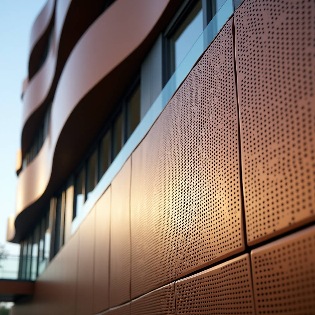
The decision to specify a Bespoke Aluminum Panel system instead of pulling from a manufacturer's standard catalog usually happens during a tense moment in the design development phase. The architect has drawn something that does not exist in any off-the-shelf product line. The general contractor has already flagged the lead time risk. The facade engineer is running wind load calculations on a geometry that standard fixing systems were never designed to accommodate. This is the exact point where custom aluminum cladding transitions from being a design aspiration to a procurement and engineering challenge that tests the entire supply chain. Getting it right means understanding how gauge selection, coating chemistry, and fabrication tolerances interact long before the first panel reaches the jobsite.
What Actually Defines a Bespoke Aluminum Panel
The term gets thrown around loosely, but in solid aluminum cladding, "bespoke" carries specific technical meaning. It is not simply choosing a non-standard color from a RAL deck. A true Bespoke Aluminum Panel program involves at least two of the following deviations from catalog products: non-rectilinear geometry, project-specific perforation patterns with open-area calculations tied to mechanical performance, custom forming radii that fall outside a factory's standard tooling, or a finish system that requires sequential coating processes across multiple vendors.
Most standard aluminum cladding panels ship as flat sheets or simple brake-formed trays in 1.0m to 1.5m widths. Bespoke work frequently demands panels in the 2.0m to 2.5m width range with compound curves, folded returns that vary in depth across a single edge, or integrated stiffener patterns that must be engineered per-panel rather than applied uniformly. The distinction matters because the engineering overhead is fundamentally different. A standard panel program might allocate two to three hours of engineering review per project. A bespoke facade involving 800 uniquely shaped panels can easily consume 80 to 120 engineering hours before fabrication begins.
Material Selection: Why 5005 and 5052 Alloys Dominate Custom Work
When a project moves into custom territory, the alloy selection is rarely negotiable. The two workhorses are 5005-H14 and 5052-H32, both from the 5xxx series magnesium-manganese family. For flat panels with moderate forming, 5005-H14 delivers an excellent balance of surface quality and cost. Tensile strength runs 145-185 MPa with elongation around 12-16%, which is sufficient for panels that require simple brake-formed returns and perimeter folds.
Where the geometry gets aggressive, 5052-H32 becomes the default. With tensile strength in the 210-260 MPa range and elongation of 14-18%, it handles tighter bend radii without micro-cracking at the outer fiber. This is particularly critical on Bespoke Aluminum Panel projects where the architect has specified a 2mm or 3mm bend radius on 3.0mm thick material. Standard 5005 will show orange-peel surface distortion or outright fracture at those ratios. The trade-off is that 5052 costs roughly 12-18% more per kilogram and has slightly lower surface uniformity post-anodizing, which becomes relevant when the finish specification calls for a Class I anodized coating rather than PVDF.
For projects in coastal or industrial environments, the 5754 alloy sometimes enters the conversation. Its higher magnesium content (2.6-3.6%) provides measurable improvement in resistance to chloride-induced pitting. Testing per ASTM G85 confirms that 5754 panels in the H32 temper outperform 5052 in salt-spray environments by a margin of roughly 300-500 hours before first visible pitting, depending on coating system. The cost premium is steep, often 20-25% above 5052, but on a waterfront project with a 30-year design life, the math often justifies the upgrade.
Coating Systems: The Gap Between Specification and Reality
Architectural specifications for custom aluminum panels almost universally call for PVDF coatings meeting AAMA 2605. The standard is well-established: a minimum 70% PVDF resin content by weight in the color coat, total dry film thickness of 25-35 microns across a primer and color coat, and performance testing that includes 4,000 hours of accelerated weathering with color change held to a maximum of 5 Delta E units.
What gets overlooked in the specification phase is that bespoke geometries create coating application challenges that standard flat panels never encounter. A panel with deep returns, perforations, and folded edges presents dramatic variations in electrostatic field strength during spray application. The Faraday cage effect causes the charged paint particles to deposit unevenly, with recessed corners receiving as little as 40-50% of the film thickness that builds up on flat surfaces. A competent applicator compensates by adjusting gun voltage, fluid delivery rate, and gun-to-part distance for each panel geometry, but this requires programming time and trial runs that a standard production line is not set up to accommodate.
The table below summarizes the key performance differences between coating chemistries commonly specified on custom aluminum cladding projects:
| Coating Type | Standard | DFT Range (microns) | Accelerated Weathering | Typical Warranty | Best Suited For |
|---|---|---|---|---|---|
| PVDF (70% resin) | AAMA 2605 | 25-35 | 4,000 hrs / ΔE ≤ 5 | 20-30 years | Exterior facades, high-UV exposure |
| PVDF (50% resin) | AAMA 2604 | 20-25 | 2,000 hrs / ΔE ≤ 5 | 10-15 years | Soffits, sheltered areas |
| FEVE Fluoropolymer | AAMA 2605 | 25-35 | 4,000 hrs / ΔE ≤ 5 | 20-30 years | High-gloss custom colors |
| Polyester (SG) | AAMA 2603 | 20-25 | 1,000 hrs / ΔE ≤ 5 | 5-10 years | Interior decorative panels |
| Anodized (Class I) | AAMA 611 | 15-20 (oxide layer) | N/A (inherently UV-stable) | 20+ years | Uniform metallic appearance |
Perforation Engineering: Open Area Is Only Half the Story
Perforated Bespoke Aluminum Panel designs have become a signature element in contemporary facade work, driven by the dual demands of solar shading and visual texture. The architectural conversation usually starts with open-area percentage and pattern geometry. The engineering conversation needs to start with something else entirely: the relationship between perforation layout and the panel's structural capacity.
A 3.0mm thick 5052-H32 panel with 40% open area does not simply lose 40% of its bending stiffness. The loss is nonlinear and depends heavily on hole diameter, pitch, and pattern orientation relative to the panel's span direction. Testing conducted in accordance with ASTM E330 shows that a panel with 8mm diameter holes on a 12mm staggered pitch at 35% open area retains approximately 55-60% of the bending stiffness of an unperforated panel of the same alloy and thickness. Reduce the hole diameter to 4mm at the same open area, and stiffness retention improves to roughly 70% because the remaining material is distributed in a more continuous matrix.
This has direct consequences for the substructure design. A facade engineer who assumes linear stiffness reduction will undersize stiffeners and attachment points, leading to excessive deflection under wind load. The correct approach is to request panel-specific finite element analysis from the fabricator, with the actual perforation pattern modeled rather than using a simplified smeared-property approach. Suppliers like Futeng® who maintain in-house engineering teams capable of per-panel FEA modeling can significantly reduce the back-and-forth during the shop drawing phase.
Wind Load Performance on Non-Standard Geometries
Standard rectangular panels have well-characterized wind load behavior. The pressure coefficients are published in ASCE 7, and the load paths through the panel to the attachment points are straightforward. Custom-shaped panels, particularly those with curved profiles, tapered widths, or large aspect ratios, break these assumptions in ways that can surprise even experienced engineers.
A curved panel with a radius of 1,500mm spanning 1,200mm between supports behaves fundamentally differently from a flat panel of the same span. The curvature introduces membrane action: as wind pressure pushes the panel inward, the arch effect carries a portion of the load in compression through the panel skin rather than purely in bending. This can be beneficial, reducing the required panel thickness or stiffener count. But it also introduces a sensitivity to boundary conditions that flat panels do not have. If the panel edges are not adequately restrained against spreading, the arch effect collapses and the panel snaps through at a load well below what the bending calculation would predict.
The table below provides a practical comparison of wind load performance across different panel configurations, based on testing per ASTM E330 at a typical 3.0 kPa design pressure:
| Panel Configuration | Alloy & Gauge | Span (mm) | Max Deflection at 3.0 kPa | Failure Mode | Stiffener Requirement |
|---|---|---|---|---|---|
| Flat, 600x1200mm | 5052-H32, 2.5mm | 600 | L/175 | Yielding at mid-span | None |
| Flat, 1000x2000mm | 5052-H32, 3.0mm | 1000 | L/120 | Yielding at attachment | 2 horizontal stiffeners |
| Curved R=1500, 1200x1800mm | 5052-H32, 2.5mm | 1200 | L/210 | Snap-through at edge | Edge restraint clips |
| Perforated 35%, 800x1600mm | 5052-H32, 3.0mm | 800 | L/95 | Tear-out at holes | 3 vertical stiffeners |
| Tapered 600-200x1500mm | 5005-H14, 2.5mm | 750 | L/140 | Torsional buckling | Full perimeter frame |
Tolerances: Where Custom Work Gets Expensive
The tolerance stack on a Bespoke Aluminum Panel project is where theoretical design meets practical fabrication reality. Standard aluminum panel tolerances per AAMA and EN standards are well-documented: panel dimensions typically carry a ±1.5mm tolerance, flatness is held to 0.5% of the panel diagonal, and hole positions are within ±0.5mm. These numbers work for rectangular panels. They break down when panels are trapezoidal, curved, or feature integrated returns that must align across multiple panel joints.
The critical issue is accumulated tolerance across a facade module. Consider a 10-panel horizontal run where each panel is nominally 1,200mm wide with a ±1.5mm tolerance. The worst-case accumulated error is ±15mm, which the joint design must absorb without visible gapping or sealant over-extension. On a bespoke project where panels are not identical, the fabricator cannot rely on statistical averaging to reduce the accumulated error. Each panel must be measured and its mating panels adjusted accordingly, which is why some custom programs require sequential fabrication and labeling rather than batch production.
For projects with particularly demanding joint tolerances, such as 8mm open joints with no sealant, the industry best practice is to specify a panel-to-panel tolerance of ±1.0mm and require the fabricator to provide a dimensional inspection report for each panel. This adds roughly 15-20% to the fabrication cost but eliminates the risk of joint misalignment that would be visible from street level.
Attachment Systems for Non-Standard Panel Geometries
The attachment system is the component most likely to fail on a custom cladding project, not because the engineering is inherently difficult but because it is the part of the system most often left to the last minute. Standard cassette systems with extruded aluminum carriers work well for flat rectangular panels. Once the panel geometry deviates, the attachment strategy must be engineered from scratch.
Three attachment approaches dominate custom work. The first is a welded aluminum subframe that is shop-assembled onto the back of each panel, with the subframe carrying the attachment clips at locations determined by the structural analysis. This approach adds weight and cost but provides maximum flexibility for unusual panel shapes. The second is direct fixing through the panel face with exposed fasteners, which is simpler but requires the architect to accept visible screw heads. The third is a hybrid system where the panel edges are folded to create integrated attachment flanges that engage with a continuous carrier rail, similar to a standard cassette system but with custom fold geometry.
Material compatibility is a persistent concern. The attachment components, typically 6063-T6 aluminum extrusions or 304 stainless steel brackets, must be isolated from the 5xxx series panel to prevent galvanic corrosion. This is standard practice but gets overlooked when custom brackets are fabricated in a hurry. The fix is straightforward: a 0.5mm EPDM or PVC isolation pad at every contact point between dissimilar metals, specified on the shop drawings and verified during the mock-up inspection.
Supply Chain Realities: Lead Times, Tooling, and Minimum Orders
A Bespoke Aluminum Panel program cannot be procured on the same timeline as standard cladding. The lead time drivers are not the raw material, which is typically available in 4-6 weeks from mill sources, but the engineering and tooling phases that precede production.
Custom tooling for brake-formed panels typically requires 3-5 weeks for design and fabrication of press brake tooling. If the project involves curved panels, the tooling timeline extends to 6-8 weeks because each radius requires a dedicated forming die set. Perforation tooling for CNC turret punches adds another 2-3 weeks if the pattern requires custom punch tooling rather than standard round-hole tooling. The finish system adds its own timeline: PVDF coating requires 7-10 days for pretreatment, primer, color coat, and clear coat application, plus curing time between each layer.
A realistic lead time for a bespoke program of 500-1,000 panels is 14-18 weeks from approved shop drawings to delivery. This assumes the fabricator has spare capacity and the coating line is not backlogged. Projects that require a 10-week lead time can sometimes be accommodated by splitting the program into phases, with the most complex panels fabricated first and simpler panels following, but this requires close coordination between the fabricator and the installation sequence on site.
Quality Verification: What to Check Before the Panels Ship
The mock-up is the single most important quality gate in a custom panel program. A full-scale mock-up, minimum 3 panels wide by 2 panels high, should be erected at the fabricator's facility or on site before production begins. The mock-up must include the actual substructure, attachment system, and joint treatment that will be used on the building. It is not sufficient to review panel samples on a table; the interaction between panels, joints, and substructure cannot be evaluated any other way.
During the mock-up review, the inspection checklist should cover at minimum: panel flatness under ambient conditions and after solar heating simulation, joint width consistency across all panel intersections, color and gloss uniformity when viewed from multiple angles, fastener engagement and torque verification, and drainage path verification for any water that penetrates the outer skin. The mock-up should also be subjected to a water spray test per ASTM E1105 to verify that the secondary drainage system functions as designed.
For projects specifying a Bespoke Aluminum Panel system with PVDF coating, color consistency across panels is a frequent source of disputes. The AAMA 2605 standard allows a Delta E of 5 units, but this is a large tolerance that can produce visible variation on a facade. The practical solution is to require the fabricator to produce all panels for a given elevation from the same coating batch, and to provide a color continuity report showing Delta E values measured across the production run. If multiple batches are unavoidable, the panels should be sorted by batch and installed on different elevations or at natural visual breaks in the facade.
Cost Structuring: Understanding the Premium
Custom aluminum panels carry a cost premium over standard products, but the premium is not distributed evenly across the cost categories. Material cost is the smallest component of the premium, typically 10-15% above standard panel material cost due to higher scrap rates and the use of 5052 or 5754 alloys. The engineering cost is where the premium is most concentrated: custom engineering can add 30-50% to the project's engineering budget compared to a standard panel program.
Fabrication labor is the second-largest premium driver. A standard rectangular panel with simple returns might require 15-20 minutes of fabrication labor. A custom panel with compound geometry, perforations, and welded stiffeners can require 2-3 hours. The labor cost difference is compounded by the fact that custom panels cannot be produced on automated lines; they require skilled sheet metal workers operating manual brake presses, TIG welding stations, and hand-finishing tools.
The total cost premium for a bespoke program, relative to a standard aluminum panel system of equivalent material thickness, typically ranges from 40% to 80% depending on complexity. The most cost-effective approach is to limit the bespoke panels to the areas of the facade where they are visually essential, and use standard panels for the remainder. This hybrid strategy preserves the architectural intent while keeping the overall cladding budget within reasonable bounds.
A well-executed Bespoke Aluminum Panel facade is the result of decisions made during the first four weeks of the design phase, not during the value engineering exercise six months later. The alloy, the coating chemistry, the perforation pattern, and the attachment strategy are not independent variables; they form a system where each decision constrains the others. Projects that treat custom panels as a procurement exercise rather than an engineering program are the ones that generate change orders, delay the schedule, and produce facades that look acceptable from a distance but fail close inspection. The fabricators who do this work well, including established suppliers like Futeng®, invest heavily in engineering capacity precisely because they know the panels themselves are only half the product. The other half is the technical support that ensures those panels perform as intended for the full design life of the building.