Custom Aluminum Facade Engineering From Alloy Selection to Wind Load and Finish Performance
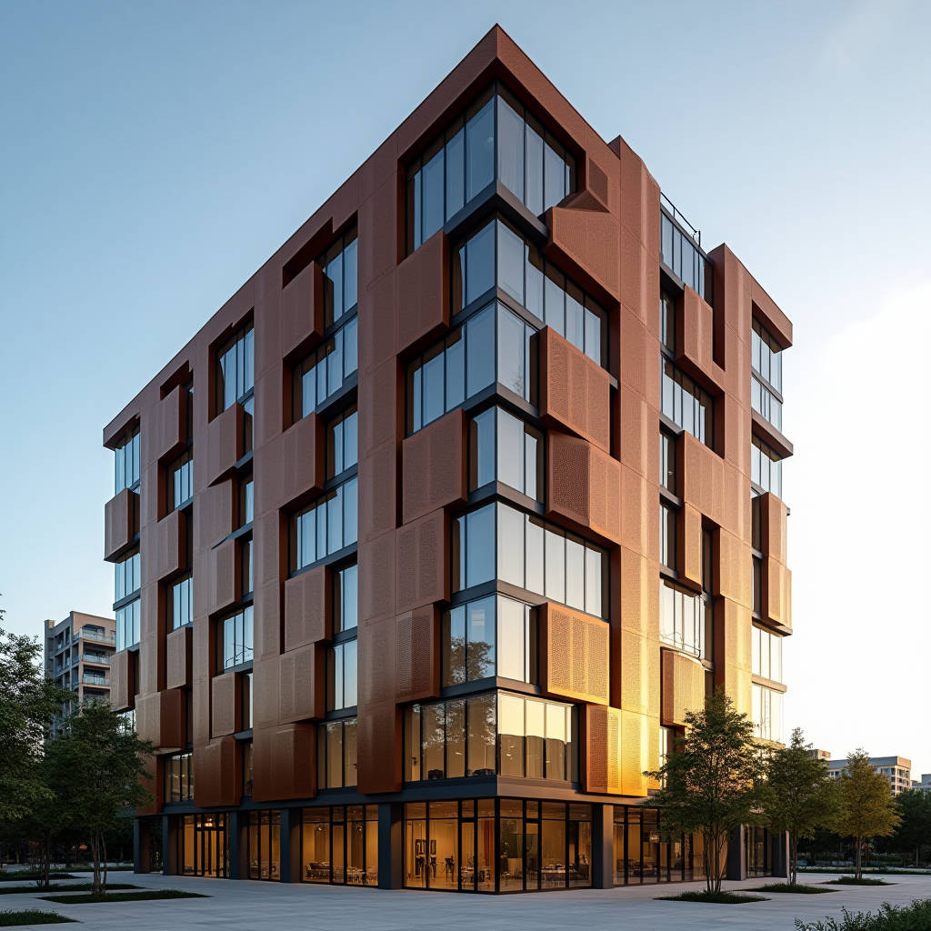
Every building envelope tells a story. For architects and facade contractors, that story starts with a single decision: how to achieve a distinctive exterior without compromising on structural performance. Custom Aluminum Facade systems built from solid aluminium panels answer this question directly. Unlike off-the-shelf cladding products that force a building into a predetermined look, a custom-engineered approach starts with the project's specific geometry, wind load requirements, and aesthetic brief — then fabricates panels to match. The result is a building skin that performs exactly as specified, with no visual compromises and no hidden structural concessions.
What Defines a Custom Aluminum Facade System
A Custom Aluminum Facade is not simply a standard panel with a unique color. The term refers to an engineered cladding system where panel dimensions, profile geometry, perforation patterns, folding sequences, and joint details are all determined by the architectural intent and site conditions of a specific project. Solid aluminium sheets — typically in 2.0mm, 2.5mm, or 3.0mm thicknesses — are cut, routed, punched, folded, and welded into precise three-dimensional forms that cannot be sourced from a catalog. The distinction matters because the engineering behind each custom panel directly affects water drainage, thermal movement accommodation, wind load resistance, and long-term flatness. A well-executed custom system accounts for all four factors simultaneously.
Fabrication begins with alloy selection. The two workhorse grades for exterior cladding are AA 3003 and AA 5005. AA 3003 offers superior formability for complex curved and folded geometries, while AA 5005 provides a smoother surface finish that responds better to anodizing and high-gloss PVDF coatings. Temper designations — typically H14 or H16 — determine the balance between bending stiffness and formability. Getting this right at the specification stage prevents oil-canning, corner cracking, and panel distortion after installation.
Engineering Considerations That Drive Panel Specifications
Wind Load and Deflection Limits
Custom panels must be engineered to the project's specific wind zone. The governing standard in most international projects is ASTM E1300, which establishes deflection limits for building envelope components. For aluminium facade panels, the typical allowable deflection is L/175 under design wind load, where L is the span between stiffeners or attachment points. A 3.0mm solid aluminium panel spanning 1200mm between supports, with properly designed stiffener ribs, can handle design pressures exceeding 2.5 kPa — sufficient for high-rise applications in most wind zones. The stiffener layout itself becomes a custom parameter: rib spacing, rib depth, and attachment method (welded studs, structural adhesive, or mechanical fasteners) all shift based on the specific pressure map of the building face.
Thermal Movement and Joint Design
Aluminium expands at approximately 0.024mm per meter per degree Celsius. On a 4-meter custom panel facing a 60°C temperature swing from winter night to summer afternoon, that translates to roughly 5.8mm of linear movement. Joint design must absorb this without transferring stress to fasteners or adjacent panels. Open-joint systems — where panels are spaced 15-20mm apart with a dark-colored weather barrier behind — handle movement elegantly and create shadow lines that enhance the facade's visual depth. Closed-joint systems with silicone gaskets require more precise movement calculations but offer better air infiltration performance. The choice between these two approaches is one of the earliest custom decisions on any project.
Surface Finishes and Long-Term Performance
Surface treatment is where custom intent meets environmental reality. The dominant coating system for solid aluminium facade panels is PVDF (polyvinylidene fluoride) resin-based coating, applied under the AAMA 2605 specification. This standard mandates a minimum total dry film thickness of 30 microns for a three-coat system (primer, color coat, clear coat) and requires passing 4,000 hours of accelerated weathering with no more than 5 Delta E color change and minimal chalking. For projects within 5 kilometers of saltwater coastlines, the specification should tighten to require seacoast-grade pretreatment with chromate conversion coating or the newer titanium-zirconium non-chrome alternatives that meet ASTM B449 Class 1A standards.
Anodizing offers a different aesthetic path. The AA-M10C22A31 specification (Class I architectural anodizing, 18-25 micron oxide layer) produces a metallic finish that cannot be matched by liquid coatings. However, anodized custom panels require careful alloy selection — only 5005 and 6061 alloys anodize to a consistent architectural finish — and the process is less forgiving of fabrication marks. Weld lines, even when ground smooth, often show through anodized finishes. This constraint must be factored into panel joint placement and fabrication sequencing during the custom design phase.
Below is a practical comparison of the three primary finish options for custom aluminium facade panels, based on real project data from coastal, urban, and industrial environments:
| Parameter | PVDF 3-Coat (AAMA 2605) | PVDF 2-Coat (AAMA 2604) | Architectural Anodizing (Class I) |
|---|---|---|---|
| Dry Film Thickness | 30-40 microns | 25-30 microns | 18-25 microns (oxide layer) |
| Accelerated Weathering | 4,000+ hours | 2,000+ hours | Not applicable (inorganic) |
| Color Range | Full RAL, custom matches | Full RAL, limited metallics | Natural metallic tones only |
| Coastal Suitability | Excellent (with seacoast pretreatment) | Good (requires additional pretreatment) | Moderate (prone to pitting in salt spray) |
| Scratch Repair | Difficult; requires recoating | Difficult; requires recoating | Impossible; scratch is permanent |
| Fabrication Mark Visibility | Hidden by coating | Hidden by coating | Weld lines and grinding marks visible |
| Typical Cost Multiplier | 1.0 (baseline) | 0.85-0.90 | 1.15-1.30 |
| Service Life Expectancy | 25-30 years | 15-20 years | 30+ years (if maintained) |
Geometry and Fabrication: Where Custom Adds Value
Perforated and Patterned Panels
Custom perforation transforms a solid aluminium panel into a multi-functional element. Perforation patterns serve as solar shading, reducing peak cooling loads by 15-30% on glazed facades depending on open area ratio and hole geometry. The structural trade-off is real: a 30% open area reduces panel bending stiffness by roughly 40-50%, requiring thicker base material or additional stiffening. CNC turret punching can produce holes from 3mm to 50mm diameter with center-to-center spacing as tight as 1.5 times the hole diameter. The pattern itself — staggered, aligned, or gradient — becomes a custom design parameter that directly affects both aesthetics and solar performance. For projects requiring both visual impact and shading performance, manufacturers like Futeng® have developed proprietary tooling that maintains flatness tolerances within 1.5mm per linear meter even on panels with 40% open area.
Curved and Folded Geometries
Single-curved panels — cylindrical bends with a consistent radius — are produced on three-roll bending machines and can achieve radii as tight as 300mm on 2.0mm AA 3003 material. Double-curved panels, which curve in two directions simultaneously, require either stretch-forming over custom dies or multi-axis CNC routing of the panel back to create a faceted approximation. The cost differential is significant: single-curved panels typically add 30-50% to the base panel cost, while true double-curved panels can multiply the base cost by 3-5 times. Many projects achieve a similar visual effect at lower cost by using folded panels with angled returns — a technique where the panel edges are brake-pressed to create a faceted, origami-like geometry that reads as curved from a distance but costs closer to flat panel fabrication.
Attachment Systems and Structural Interfaces
The attachment system is the least visible but most consequential part of any Custom Aluminum Facade. Panel attachment methods fall into three categories: face-fixed (exposed fasteners through the panel face), edge-gripped (concealed clips that grip panel return legs), and rear-ventilated (panels hung on a substructure with the attachment hidden behind). The choice affects thermal performance, aesthetic cleanliness, and installation speed. Rear-ventilated systems, governed by ISO 13056 for rainscreen design principles, create a continuous ventilation cavity behind the panels that manages moisture and reduces thermal bridging through the building envelope.
The substructure itself — typically aluminium extruded profiles in 6063-T6 alloy — must be engineered to accommodate the panel layout while transferring wind loads back to the primary structure. Custom panel layouts with irregular geometries or mixed panel sizes require careful bracket placement. The industry standard for bracket spacing is 600mm to 1200mm vertically and 800mm to 1500mm horizontally, but these numbers shift based on the specific wind load calculations and the allowable deflection of the supporting mullions. Thermal isolation pads between the bracket and the primary structure are essential — without them, each bracket becomes a thermal bridge that can reduce the effective R-value of the wall assembly by 15-25%.
Quality Control and Factory Testing
Custom panels demand custom quality control protocols. Standard QC for solid aluminium facade panels should include: dimensional verification of every panel against shop drawings (tolerance: ±1.5mm on length and width, ±1.0mm on diagonal difference), coating thickness measurement using eddy-current gauges (minimum 5 readings per panel, recorded and traceable), gloss level verification at 60° geometry per ASTM D523, and cross-hatch adhesion testing per ASTM D3359 Method B. For projects with particularly stringent flatness requirements, a 2-meter straight-edge check with a 3mm maximum gap specification should be added to the inspection checklist.
Factory witness testing — where the client or their representative observes testing in person — adds a layer of confidence on large projects. A typical witness test protocol includes: selecting random panels from the production batch, performing dry film thickness measurements, conducting MEK rub tests for cure verification (50 double rubs with no coating removal), and assembling a mock-up section of at least 3 panels by 3 panels to verify joint alignment and overall flatness. This mock-up also serves as the installation quality benchmark for the site team.
Procurement Strategy for Custom Facade Projects
Procuring a Custom Aluminum Facade requires a different approach than buying standard cladding products. The critical path runs through design development, not just production lead time. A typical timeline for a custom facade package of 2,000-5,000 square meters looks like this: 4-6 weeks for shop drawing development and approval, 2-3 weeks for material procurement (aluminium coil and extrusion), 4-6 weeks for fabrication, and 1-2 weeks for surface treatment. Total lead time from order to delivery: 11-17 weeks. This timeline compresses slightly for repeat projects but cannot be meaningfully shortened without compromising either design review or quality control steps.
Specification packages should include: architectural intent drawings showing panel layout and joint locations, a performance specification defining wind loads and deflection criteria, a finish specification referencing the appropriate AAMA or Qualicoat standard, and a scope document that clearly delineates who supplies the substructure, brackets, fasteners, and weather barrier. Ambiguity in any of these four documents is the most common source of variation claims and schedule delays on custom facade projects.
Cost Drivers and Value Engineering Pathways
The cost of a Custom Aluminum Facade system breaks down into material (25-35%), fabrication labor (30-40%), surface finishing (15-20%), and substructure with accessories (15-25%). The biggest cost drivers are panel complexity (number of folds, perforations, or curves per panel), finish specification (AAMA 2605 three-coat costs roughly 20% more than AAMA 2604 two-coat), and panel size consistency (many unique panel sizes drive up fabrication setup time). Value engineering without sacrificing design intent typically focuses on three areas: rationalizing panel sizes to reduce the number of unique dimensions, switching from welded corners to mechanically fastened corners where the joint is hidden, and using standard rather than custom extrusion profiles for the substructure. These three moves can reduce total facade cost by 10-18% while preserving the architectural vision.
For complex geometries, the fabrication approach matters enormously. A panel with four folded returns and two stiffeners might take 45 minutes to fabricate manually. The same panel on a semi-automated CNC folding cell takes 12 minutes. The labor cost difference is real, but the quality difference is equally important — automated folding produces consistent bend angles and return leg dimensions that manual fabrication cannot match. On projects exceeding 3,000 square meters, the case for automated fabrication is compelling on both cost and quality grounds.
"The difference between a good custom facade and a problematic one is rarely visible in the first six months. It shows up in year three, when the joints are still aligned, the coating hasn't chalked, and there are no signs of water ingress behind the panels. That's what engineering upfront buys you."
Installation Sequencing and Site Coordination
Custom panels arrive on site in a specific sequence that matches the installation plan. Unlike standard cladding where any panel fits any location, custom panels are fabricated for specific positions on the building grid. This means the installation team must follow the panel schedule precisely, and any panel damaged on site requires a replacement fabricated to the same unique dimensions — a process that typically takes 3-4 weeks. Smart project teams order 2-3% spare panels of the most complex geometries to cover site damage without delaying the program.
Site storage matters too. Solid aluminium panels with PVDF finishes should be stored vertically on A-frame racks, separated by protective interleaving, and kept dry. Panels stored flat or exposed to standing water risk permanent staining and coating delamination. The protective film applied at the factory — typically a 50-micron polyethylene film with UV inhibitors — should remain in place until immediately before installation, but must be removed within 30 days of exposure to direct sunlight to prevent adhesive transfer to the panel surface.
The intersection between custom panels and adjacent building elements — windows, louvers, signage, lighting — requires careful coordination. Each penetration through a custom panel for a lighting fixture or sign bracket must be reinforced locally to prevent stress concentration and cracking. The reinforcement detail, typically a welded aluminium doubler plate on the panel back, should be specified in the shop drawings and fabricated in the factory, not improvised on site.
Custom Aluminum Facade systems represent a significant investment in a building's long-term performance and identity. The engineering decisions made during design development — alloy selection, stiffener layout, joint type, finish specification, and attachment method — determine whether that investment delivers 30 years of reliable service or becomes a source of recurring maintenance costs. For architects and contractors navigating this territory, the key is to engage with facade engineering early, specify performance requirements clearly, and select fabrication partners who can demonstrate both technical capability and a track record of delivering complex custom projects on time and to specification.