Closed Joint Aluminum Facade Engineering Gasket Selection Drainage and Thermal Movement for High Rise Rainscreens
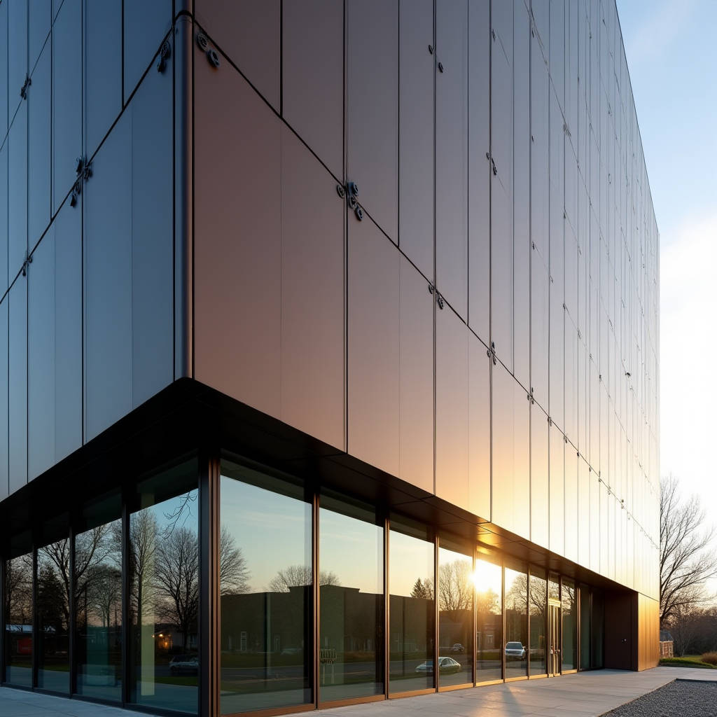
Water doesn't forgive shortcuts. In rainscreen design, the joint is where a facade proves whether it was engineered or just assembled. A Closed Joint Aluminum Facade eliminates the open cavity between panels, creating a continuous exterior plane that relies entirely on precise gasket integration, drainage logic, and thermal movement accommodation. When a contractor in Manchester emailed us last winter about a 14-story residential tower where wind-driven rain had penetrated an open-joint system during back-to-back storms, the conversation shifted quickly from aesthetics to the physics of pressure equalization. That project, and dozens like it, underscore why the closed joint approach demands a different level of detailing discipline. The aluminum panels themselves—typically 2.5mm to 3.0mm thick 3003-H14 or 5052-H32 alloy sheets with PVDF coatings—are only half the story. The other half lives in the millimeters between them.
What Actually Defines a Closed Joint in Aluminum Facade Engineering
A closed joint is not simply a tight gap. The term describes a rainscreen configuration where the horizontal and vertical joints between solid aluminum panels are sealed with EPDM gaskets, silicone weather seals, or integrated compression profiles that prevent direct water ingress into the cavity behind the panel. Unlike open-joint systems that rely on a drained and ventilated cavity with a secondary weather barrier, the closed joint approach makes the outer aluminum skin the primary water-shedding surface.
Joint widths typically range from 6mm to 20mm, depending on panel size, thermal expansion calculations, and the specific gasket profile selected. The Aluminum Association's guidelines for solid aluminum sheet suggest a thermal movement coefficient of approximately 2.4 × 10⁻⁵ per °C. For a 3-meter panel subjected to a 60°C temperature swing, that translates to roughly 4.3mm of linear movement. The joint must absorb this without compromising the seal or transferring stress to the panel edges.
The distinction matters because the entire drainage strategy changes. In a closed joint system, any moisture that does bypass the outer seal must be managed by internal horizontal gutters, weep holes at panel base joints, and carefully sequenced lapping that directs water outward at each floor level. This is fundamentally different from the "let it drain and dry" philosophy of open joints.
Why Architects Specify Closed Joint Aluminum Facades for High-Rise Projects
Three factors drive the decision toward closed joint systems. The first is wind-driven rain resistance. Testing at the Building Research Establishment has shown that at wind speeds exceeding 20 m/s, water droplets can travel horizontally across a 25mm open cavity and saturate the insulation layer behind the rainscreen. A closed joint system with properly compression-set EPDM gaskets tested to ASTM E1105 standards eliminates this pathway.
The second factor is thermal performance. Open joints allow air to circulate freely behind the cladding, which can strip heat from the building envelope in winter. A closed joint system, when combined with continuous exterior insulation, creates a more stable thermal boundary. Energy modeling data from multiple projects indicates that closed joint aluminum facades can reduce thermal bridging losses by 12-18% compared to equivalent open-joint configurations, depending on climate zone and insulation thickness.
The third driver is aesthetic. Many architects pursuing a monolithic, smooth facade appearance find that open joints create visible shadow lines that disrupt the intended visual massing. Closed joints with color-matched sealant produce a near-seamless surface, which is particularly valued on projects with large-format panels (up to 1500mm × 4000mm in solid aluminum).
Gasket Selection: The Component That Makes or Breaks the System
If there is one detail that separates a durable closed joint aluminum facade from a callback nightmare, it is the gasket. EPDM (ethylene propylene diene monomer) remains the industry standard for its UV resistance, compression set recovery, and temperature range (-40°C to +120°C). But not all EPDM is equal. The critical specification is compression set at elevated temperature, tested per ASTM D395 Method B. A value below 25% after 22 hours at 70°C indicates a formulation that will maintain sealing force over decades.
Silicone gaskets offer superior temperature resistance but cost roughly 2.5 to 3 times more than EPDM and have lower tear strength. They are typically reserved for applications where the aluminum panel surface temperature may exceed 100°C—rare in ventilated rainscreen applications but relevant in certain desert climates or near industrial heat sources.
The table below compares performance characteristics of the three primary gasket material options for closed joint aluminum facade applications:
| Property | EPDM (Solid) | Silicone (Solid) | TPE (Thermoplastic) |
|---|---|---|---|
| Temperature Range | -40°C to +120°C | -60°C to +200°C | -30°C to +100°C |
| Compression Set (70h/100°C) | 20-30% | 10-20% | 35-50% |
| UV Resistance | Excellent | Outstanding | Moderate (requires stabilizers) |
| Relative Cost per Linear Meter | 1.0x (baseline) | 2.5-3.0x | 0.7-0.9x |
| Typical Service Life | 20-30 years | 30+ years | 10-15 years |
| Tear Strength | Good | Fair | Good to Excellent |
Gasket geometry is equally important. Barbed-leg profiles that lock into extruded aluminum carrier channels provide positive mechanical retention and prevent the gasket from pulling out during thermal cycling. Co-extruded designs with a harder durometer spine and softer sealing bulb offer the best combination of grip and conformability. When Futeng® supplies closed joint aluminum facade panels to contractors in Southeast Asia and the Middle East, the technical team routinely recommends specifying gasket hardness at 60±5 Shore A for the bulb and 70±5 Shore A for the retention leg, based on field performance data from completed projects.
Drainage Engineering Behind the Sealed Face
A closed joint aluminum facade is not hermetically sealed. The system must assume that some water will eventually penetrate—through aging gaskets, installation tolerances, or sealant joint failure—and must provide a managed path for that water to exit. This is the concept of "secondary defense" and it is codified in standards such as ASTM E1105 and AAMA 501.1.
The drainage strategy typically involves three layers of protection. The outermost layer is the gasket seal itself. Behind that, a horizontal aluminum flashing or gutter at each floor level collects any water that bypasses the primary seal and channels it to vertical drainage paths at the panel edges. These vertical paths empty through weep holes—typically 6mm to 8mm diameter slots at 600mm centers—located at the bottom edge of each panel course.
The third layer is the air and water barrier on the structural backup wall. In a properly designed closed joint system, this barrier should rarely see liquid water. But it must be detailed with the same rigor as in an open-joint system because the consequences of failure are higher: trapped moisture in a less-ventilated cavity can lead to corrosion of aluminum sub-framing and degradation of insulation performance.
Thermal Movement: Calculating Joint Widths That Actually Work
Joint width is not an aesthetic choice. It is a calculated value derived from panel dimensions, material properties, and expected temperature range. The formula is straightforward:
Minimum Joint Width = (Panel Length × CTE × ΔT) + Installation Tolerance + Sealant Movement Capability Allowance
Where CTE (coefficient of thermal expansion) for 3003 aluminum alloy is 23.2 × 10⁻⁶ mm/mm/°C, and ΔT is the maximum expected temperature differential between installation and service conditions. For a 3-meter panel in a climate with a 70°C annual swing (from -10°C winter night to 60°C summer solar gain on a dark PVDF surface), the calculation yields:
3,000mm × 23.2 × 10⁻⁶ × 70°C = 4.87mm of linear expansion. Adding 2mm for installation tolerance and 3mm for sealant movement reserve gives a minimum joint width of approximately 10mm. Narrower joints risk panel edge contact and coating damage; wider joints increase sealant volume and cost while reducing the visual continuity that architects seek.
This is where the engineering of a closed joint aluminum facade diverges from rule-of-thumb installation. Panel size must be coordinated with joint width at the shop drawing stage, not resolved on site. Pre-notched panel edges, factory-applied gasket channels, and numbered installation sequences all contribute to maintaining consistent joint widths across large facade areas.
Coating Systems and Joint Aesthetics
The closed joint configuration places unique demands on the panel coating system. Because the joint is sealed rather than shadowed, any color variation between adjacent panels becomes immediately visible. This drives a requirement for tighter color tolerances than open-joint systems, where the shadow gap masks minor differences.
PVDF (polyvinylidene fluoride) coatings based on Kynar 500® or Hylar 5000® resin systems remain the industry benchmark for exterior aluminum facades. The specification should call for a minimum of 70% PVDF resin by weight in the color coat, with a total dry film thickness of 30-35 microns for a two-coat system or 40-45 microns for a three-coat system that includes a clear topcoat. Testing per AAMA 2605 requires color retention of ΔE ≤ 5 after 10 years of South Florida exposure.
For closed joint applications, the panel edges that contact gaskets should receive a minimum 1.5mm edge relief radius and full coating coverage to prevent corrosion initiation at the cut edge. Some fabricators apply a clear edge sealant as an additional protective measure, though this adds cost and process time.
Installation Sequence and Quality Control
Closed joint aluminum facade installation follows a logic that differs from open-joint work. Because each panel's gasket must compress against its neighbor, the installation sequence must proceed in a single direction across the facade—typically left to right and bottom to top—without skipping bays. Installing panels out of sequence creates gaps that cannot be closed without removing and re-installing adjacent panels.
The sub-frame alignment tolerance is tighter as well. While open-joint systems can tolerate ±3mm in rail alignment without visible consequence, a closed joint system demands ±1.5mm across any 3-meter span to maintain consistent gasket compression. This typically requires laser-leveled vertical tracks and shim-adjustable bracket systems.
Field quality control should include a water spray test on a representative mockup section, conducted per ASTM E1105 at a minimum differential pressure of 300 Pa. The test should be performed after the first 50 square meters of facade are installed, not at the end of the project, to allow corrective action before the system is fully committed.
Cost Structure Comparison: Closed Joint vs. Open Joint
The cost difference between closed and open joint systems is not simply a matter of gasket cost. The table below breaks down the primary cost drivers based on project data from mid-rise commercial facade installations:
| Cost Element | Open Joint System | Closed Joint Aluminum Facade | Delta |
|---|---|---|---|
| Solid Aluminum Panels (3.0mm, PVDF) | $85-110/m² | $85-110/m² | Same |
| Sub-frame (Aluminum) | $35-50/m² | $40-55/m² | +10-15% |
| Gaskets & Seals | $5-8/m² | $18-30/m² | +200-300% |
| Installation Labor | $45-65/m² | $55-80/m² | +15-25% |
| Waterproofing Behind | $30-45/m² | $20-30/m² | -30% |
| Total Installed Cost | $200-278/m² | $218-305/m² | +8-12% |
The premium for a closed joint aluminum facade typically ranges from 8% to 12% on total installed cost. However, the reduced waterproofing requirement behind the rainscreen partially offsets the higher gasket and labor costs. Over a 30-year building lifecycle, the energy savings from reduced cavity ventilation can make the closed joint option the lower total cost of ownership in heating-dominated climates.
Common Failure Modes and How to Prevent Them
After reviewing warranty claims and site investigation reports across multiple projects, several recurring failure patterns emerge in closed joint aluminum facade systems. The most frequent is gasket pullout, where the sealing profile disengages from its carrier channel due to thermal cycling combined with wind suction. Prevention requires specifying gaskets with barbed retention legs and verifying pullout resistance through testing per the manufacturer's protocol.
The second common failure is panel edge corrosion at the gasket contact line. This occurs when the PVDF coating at the panel edge is insufficient or damaged, and moisture trapped against the gasket initiates filiform corrosion. The solution is factory-applied edge coating with a minimum 25-micron dry film thickness and a requirement that cut edges be deburred and coated within 24 hours of fabrication.
Water staining at weep holes is a third issue. If weep holes are too small or poorly positioned, water accumulates in the horizontal gutters and eventually overflows, carrying dissolved aluminum salts that leave white streaks on the panel surface below. Weep holes should be a minimum of 6mm × 20mm slots, located at the lowest point of each horizontal gutter section, and should be cleaned during annual facade maintenance.
Specifying a Closed Joint Aluminum Facade: Key Contract Clauses
For procurement managers and specification writers, the following points should be addressed in the contract documents to ensure the delivered system performs as intended:
- Material certification: Require mill test certificates for aluminum sheet confirming alloy (3003-H14 or 5052-H32) and thickness tolerance per Aluminum Association standards. Minimum thickness at any point should not be less than 90% of nominal.
- Coating warranty: Specify a minimum 20-year film integrity warranty and 15-year color retention warranty per AAMA 2605 for PVDF coatings. Require the coating applicator to be approved by the resin manufacturer.
- Gasket performance: Reference ASTM D395 for compression set, ASTM D2240 for hardness, and require UV resistance testing per ASTM G154 Cycle 1 for minimum 2,000 hours with no visible cracking or color change.
- Mockup requirement: Mandate a site mockup of at least 10 square meters, including a corner condition and window interface, to be tested for water penetration per ASTM E1105 at 300 Pa minimum.
- Installation tolerance: Specify maximum deviation of ±1.5mm in joint width across any 3-meter measurement, verified by the contractor's quality control report and subject to the specifier's inspection.
When a Closed Joint System Is the Wrong Choice
Engineering honesty requires acknowledging that closed joint aluminum facades are not universally appropriate. In climates with extreme humidity and low wind exposure—tropical Southeast Asia, for example—the reduced cavity ventilation can lead to condensation accumulation behind the panels if the dew point calculation is not carefully managed. A hygrothermal analysis per ISO 13788 should be performed to verify that interstitial condensation risk is acceptable.
Buildings with complex geometries—curved facades, folded planes, or highly articulated surfaces—present challenges for closed joint systems because the gasket compression must be uniform along the entire joint length. Variable-radius curves require custom-gasket profiles or segmented panel approaches that can drive costs significantly above the 8-12% premium cited earlier.
Projects with compressed construction schedules may also struggle with closed joint systems. The sequential installation requirement means that facade work cannot be accelerated by deploying multiple crews to different building elevations simultaneously, as is common with open-joint rainscreens. This constraint should be discussed with the contractor during the design phase, not discovered during construction.
The closed joint aluminum facade represents a specific engineering solution to a specific set of performance requirements. It excels where wind-driven rain resistance, thermal continuity, and seamless aesthetics are priorities. It demands more from the gasket, the installer, and the quality control process. When those demands are met, the result is a facade that performs quietly and durably for decades. When they are not, the joints become the first place the building tells you something is wrong.