Rainscreen Aluminum Cladding Subframe Engineering for Wind Load Performance in High Rise Facades
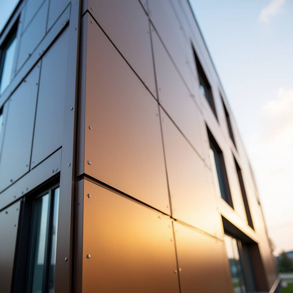
Architects and facade engineers evaluating Rainscreen Aluminum Cladding for mid-rise and high-rise projects often face a single, recurring question: can the system handle the wind loads at the upper floors without ballooning costs or compromising the cavity depth? The answer depends less on the panel itself and more on the subframe engineering behind it. Solid aluminum panels — typically 2.0mm to 3.0mm thick 3003-H14 or 5052-H32 alloy sheets with PVDF or FEVE coating — offer excellent strength-to-weight ratios. But the real performance differentiator lies in the aluminum extruded rail and bracket assembly, the fastener spacing, and how the entire system transfers negative wind suction back to the primary structure. This article examines the structural logic behind aluminum rainscreen subframe design, the calculation methodologies that separate compliant systems from risky ones, and the fabrication details that determine whether a 40-story facade stays flat under a 3.0 kPa design load.
Why Subframe Engineering Defines Rainscreen Performance
The rainscreen principle itself is straightforward: an outer cladding layer deflects the bulk of wind-driven rain, a ventilated cavity allows pressure equalization and moisture escape, and an inner weather barrier handles any residual water. The aluminum panel is the visible face, but the subframe is the skeleton that keeps it attached to the building through decades of thermal cycling, wind gusts, and differential movement.
In a typical Rainscreen Aluminum Cladding assembly, the subframe consists of aluminum L-brackets or T-brackets anchored to the structural backup wall, vertical extruded rails (often T-profiles or hat channels), and sometimes horizontal girts. The panels attach to these rails via visible rivets, hidden clips, or cassette-style hanging systems. Every component in this load path must be sized for the project-specific wind loads — and those loads increase exponentially with building height and corner-zone exposure.
A study published by the RIBA Journal noted that rainscreen fastener failures in high-wind events were almost always traced to undersized subframe components rather than panel material failure. The aluminum skin itself rarely tears; what fails is the connection between the panel return leg and the rail, or the bracket-to-substrate anchor pullout. This is why AAMA 508 and the upcoming AAMA 509 standards devote extensive testing protocols to the entire assembly, not just the panel.
Wind Load Calculation: From Building Code to Bracket Spacing
Wind load on a rainscreen system is not a single number. It varies by building zone — field, edge, and corner — and by the height above ground. Per ASCE 7-22, the design wind pressure for components and cladding on a 100-foot-tall building in Exposure Category B can range from 1.0 kPa in the field zone to over 2.5 kPa in corner zones. For a 300-foot tower in Exposure C, corner zone pressures can exceed 4.0 kPa.
The load path works as follows: wind suction pulls the panel outward; the panel transfers that load through its connection points to the vertical rails; the rails transfer it to the brackets; the brackets transfer it to the anchors embedded in the concrete slab or steel stud backup. Each interface has a capacity limit. A 3.0mm solid aluminum panel with a 600mm x 400mm return leg can typically handle significant suction, but if the rail is a 1.5mm-thick galvanized steel section with 900mm bracket spacing, the rail may deflect excessively long before the panel shows any distress.
Engineers should request the following data from subframe suppliers:
- Allowable span tables for vertical rails under both positive and negative wind loads, with deflection limits of L/175 or L/240 depending on panel joint tolerance requirements.
- Bracket pull-out and shear capacities for the specific substrate — concrete, CMU, or cold-formed steel stud — with appropriate safety factors (typically 3:1 or 4:1).
- Clip engagement data for cassette systems, including the pull-off force required to disengage the panel from the rail under negative pressure.
- Thermal movement accommodation ranges: a 3-meter aluminum rail can expand approximately 4.5mm over a 60°C temperature swing, and fixed-point engineering must prevent buckling.
Aluminum vs. Steel Subframes: Weight, Corrosion, and Installation Speed
Many contractors default to galvanized steel subframes because of lower upfront material cost. But on projects exceeding 10 stories, the weight penalty becomes significant. A 6063-T6 aluminum extruded rail weighs roughly one-third of an equivalent steel section. Over 10,000 square meters of facade, the weight difference can exceed 8 metric tons — directly impacting structural steel tonnage, crane time, and manual handling fatigue.
Corrosion is another factor. Galvanized steel in a ventilated cavity still faces moisture exposure, particularly in coastal or industrial environments. The zinc coating on G90 steel provides sacrificial protection, but cut edges and fastener penetrations remain vulnerable. Aluminum extrusions eliminate this concern entirely for the subframe, matching the panel material and avoiding galvanic corrosion when paired with stainless steel fasteners. Futeng® supplies both the solid aluminum panels and compatible 6063-T6 extruded subframe components, which simplifies the supply chain and eliminates the finger-pointing that occurs when panel and subframe come from different vendors.
Installation speed also favors aluminum. The straightness tolerance of extruded aluminum rails — typically within 1mm over a 3-meter length — means less shimming and adjustment on site. Steel rails often arrive with mill camber that requires field correction, adding labor hours that erode the initial material cost savings.
| Parameter | Aluminum Subframe (6063-T6) | Galvanized Steel Subframe (G90) |
|---|---|---|
| Weight per linear meter (typical T-rail) | 0.9 – 1.4 kg/m | 2.7 – 4.2 kg/m |
| Corrosion resistance in coastal zones | Excellent (no coating required) | Moderate (zinc sacrificial; cut-edge risk) |
| Thermal expansion (per 3m, ΔT=60°C) | ~4.5mm | ~2.1mm |
| Straightness tolerance (3m length) | ≤1.0mm | ≤2.5mm (typical mill spec) |
| Material cost index (relative) | 1.4 – 1.6x | 1.0x (baseline) |
| Installation labor adjustment | 10-15% faster (less shimming) | Baseline |
| Galvanic compatibility with aluminum panels | Compatible (use SS fasteners) | Requires isolation tape/pads |
Fastener Engineering: The Overlooked Failure Point
Stainless steel fasteners are standard in Rainscreen Aluminum Cladding assemblies, but the grade selection matters more than most specifiers realize. A2 (304) stainless is adequate for inland urban environments. A4 (316) stainless is required within 5 kilometers of a coastline or in industrial zones with sulfur dioxide exposure. The incremental cost is negligible — perhaps $0.03 per fastener — but the consequence of chloride stress corrosion cracking in A2 fasteners near the ocean is complete joint failure within 3 to 5 years.
Fastener pull-out from the aluminum rail is governed by the thread engagement depth and the rail wall thickness. A self-tapping screw into a 2.0mm-thick aluminum rail wall provides roughly 1.8 kN of pull-out capacity in 6063-T6. For a panel with four attachment points experiencing a 2.5 kPa suction load over a 0.6 square meter tributary area, the per-fastener demand is only about 0.38 kN — well within capacity. But if the installer over-drives the screw and strips the thread, that capacity drops to near zero, and there is no visual indication of the defect from the outside.
Rivet-based systems avoid the thread-stripping risk but introduce a different concern: blind rivets with carbon steel mandrels will rust inside the cavity, leaving orange staining on the weather barrier and eventually losing clamp force. The specification should explicitly require stainless steel mandrels for all blind rivets used in the assembly.
Thermal Bridging and the Subframe Connection
The ventilated cavity behind a rainscreen means the subframe is not part of the building's thermal envelope in the traditional sense. However, the bracket penetrations through the insulation layer create point thermal bridges. Each aluminum bracket connecting the rail to the concrete slab can represent a thermal bridge with a linear transmittance of 0.02 to 0.08 W/mK, depending on the bracket geometry and whether a thermal break pad is used.
For projects targeting Passive House or LEED v4.1 energy performance, these bridges add up. A facade with brackets at 600mm horizontal x 1200mm vertical spacing has roughly 1.4 brackets per square meter. Without thermal breaks, the cumulative heat loss through these penetrations can reduce the effective R-value of the insulation layer by 15% to 25%. Low-thermal-conductivity shims — typically made from fiberglass-reinforced nylon or rigid PVC — can cut this penalty by half, and they add less than $2 per bracket.
The American Architectural Manufacturers Association (AAMA) has been developing test methods for rainscreen thermal performance, and specifiers should ask subframe suppliers for independently verified thermal transmittance data rather than relying on generic assumptions.
Panel Thickness, Return Leg Depth, and Flatness Under Load
Solid aluminum panels for rainscreen applications are typically specified at 2.0mm, 2.5mm, or 3.0mm thickness. The choice depends on panel dimensions and wind load, but also on the aesthetic requirement for flatness. A 2.0mm panel measuring 1200mm x 2400mm will exhibit visible oil-canning under thermal expansion unless the return legs are deep enough — typically 25mm to 35mm — and the panel is properly stress-relieved after fabrication.
For large-format panels exceeding 1.5 square meters, 2.5mm or 3.0mm thickness is strongly recommended. The incremental material cost is modest: moving from 2.0mm to 2.5mm adds about 2.3 kg/m² and roughly 15% to the raw aluminum cost. The payoff is dramatically reduced waviness and the ability to span wider rail spacing without intermediate stiffeners.
Perforated panels introduce additional structural considerations. A panel with 30% open area has effectively lost 30% of its bending stiffness. The remaining material must still carry the full wind load, and the perforation pattern — staggered vs. straight grid, hole diameter, edge distance — affects stress concentration. Finite element analysis is recommended for perforation ratios above 25%, and the minimum ligament width between holes should be at least 1.5 times the material thickness.
Pressure Equalization: Why Cavity Compartmentalization Matters
The term "rainscreen" implies pressure equalization, but true pressure-equalized design requires deliberate compartmentalization of the cavity. Without vertical and horizontal compartment seals, wind pressure on one zone of the facade can propagate through the cavity to zones with different external pressures, creating a pressure differential that drives water inward.
AAMA 508-7 defines the test protocol for pressure-equalized rainscreen systems. To pass, the system must demonstrate that the cavity pressure tracks the external pressure within a specified time lag and that water penetration is limited to a controlled amount. This requires careful detailing of compartment barriers — typically aluminum sheet or EPDM gaskets — at every floor line and at vertical intervals not exceeding 6 meters.
Compartmentalization adds cost, but it also reduces the amount of water that reaches the weather barrier. For projects in high-rainfall climates — Miami, Singapore, Vancouver — the investment in proper compartment seals pays back through reduced long-term maintenance of the weather barrier and lower risk of concealed water damage. The NFPA 285 fire test also requires specific cavity detailing, and compartment barriers can serve double duty as fire stops when designed with intumescent materials.
Coating Systems and Long-Term Subframe Compatibility
PVDF (polyvinylidene fluoride) coatings dominate the Rainscreen Aluminum Cladding market for good reason. A 70% PVDF resin system — such as PPG Duranar or AkzoNobel Trinar — applied at 25-35 microns dry film thickness over a chromate conversion coating, delivers 20+ years of color retention and chalk resistance in most climates. FEVE (fluoroethylene vinyl ether) coatings extend that to 30+ years and offer higher gloss ranges, but at roughly 30% higher cost.
The coating specification must address not just the panel face but also the return legs and the subframe components. Uncoated aluminum extrusions in the cavity will oxidize harmlessly, but if the project uses a dark-colored panel, the visible edges of the return leg should be coated to match. Some fabricators cut costs by leaving return legs mill-finish, which creates a visible silver line at panel joints — a detail that becomes obvious on dark bronze or charcoal facades.
Powder coating is an alternative for inland applications with moderate UV exposure. AAMA 2604-compliant powder coat offers good color stability at lower cost than PVDF, but the film thickness is higher — typically 60-80 microns — which can affect the fit of tight-tolerance cassette systems. The specifier should confirm that the panel fabricator adjusts the brake press settings to account for the thicker coating when forming return legs.
Supply Chain Considerations for International Projects
For construction managers sourcing Rainscreen Aluminum Cladding internationally, the subframe compatibility question becomes critical. A panel fabricated in one country to a specific rail profile may not fit a locally sourced subframe system. The most reliable approach is to source panels and subframe from a single supplier with proven extrusion die compatibility.
Shipping solid aluminum panels internationally requires careful packing. Panels with 35mm return legs nest efficiently, but the interleaving material — typically polyethylene foam or kraft paper — must not transfer to the coated surface under the heat and pressure of a container voyage. This is a known failure mode: panels arrive on site with ghosting marks from the protective interleaving, requiring on-site cleaning or, in severe cases, re-coating.
Lead times for custom-extruded subframe components typically run 6 to 8 weeks from die approval, plus 4 to 6 weeks for panel fabrication. Projects should plan for a 14-week total lead time from shop drawing approval to delivery, with an additional 2 weeks for ocean freight to North American or European ports. Air freight is available for emergency orders but adds $3 to $5 per kilogram — prohibitive for all but the smallest quantities.
The ASTM International standards for aluminum sheet — ASTM B209 for the base material and ASTM E84 for surface burning characteristics — should be referenced in all purchase specifications. For projects in the Middle East, the local equivalent is often BS EN 485, and the specifier should confirm that the mill test certificates match the project's governing code.
Installation Tolerances and Quality Control
A well-engineered subframe means nothing if the installation does not respect the design tolerances. The backup wall flatness is the starting point: a concrete slab with ±10mm deviation over 3 meters will translate that irregularity through the brackets and rails to the panel face. The industry standard for rainscreen backup wall flatness is ±3mm over 3 meters, measured with a straightedge. Achieving this on cast-in-place concrete often requires localized grinding or leveling screeds, which should be accounted for in the general contractor's scope — not left to the cladding installer.
Bracket alignment is the next checkpoint. If brackets are installed with a 2mm vertical offset from the intended plane, the rails will follow that offset, and the panel joints will show a visible step. Laser-leveled bracket installation with continuous quality checks is the only reliable method for high-end architectural facades. The incremental cost of laser surveying is roughly $0.50 per square meter of facade area — a small price for joint alignment that passes a 3-meter straightedge check.
Panel joint width consistency is the final visual test. A 12mm open joint that varies by ±3mm is immediately noticeable from street level. The subframe rail spacing and the panel return leg dimensions must be coordinated so that the panel's natural position on the rail produces the specified joint width without requiring field adjustment. Cassette systems with pre-formed hanging tabs are inherently more repeatable than face-fixed panels that rely on installer judgment for positioning.
Making the Engineering Decision
Rainscreen Aluminum Cladding is not a commodity product where the lowest bidder wins. The structural integrity of the system depends on a chain of engineering decisions: wind load calculation methodology, subframe material selection, bracket spacing, fastener grade, thermal break detailing, and installation tolerance control. Any weak link in that chain can turn a 50-year facade into a 10-year liability.
For specifiers, the most important document is not the panel data sheet but the subframe engineering package: span tables, bracket capacity charts, thermal movement calculations, and AAMA 508 test reports for the complete assembly. For contractors, the focus should be on installer training for the specific system being used — generic rainscreen experience does not guarantee competence with a particular subframe platform. And for building owners, the long-term value lies in a system where every component from the aluminum skin to the stainless steel anchor has been sized for the specific wind and exposure conditions of the site, not copied from a previous project in a different climate zone.
Engineering the subframe correctly does not necessarily cost more. It costs attention. The aluminum panel will look the same on day one regardless of the bracket spacing behind it. The difference reveals itself on day 1,825 — five years in — when the facade still looks exactly as it did on the day of handover.