Ventilated Aluminium Facade Engineering Load Paths Panel Gauges and Cavity Performance
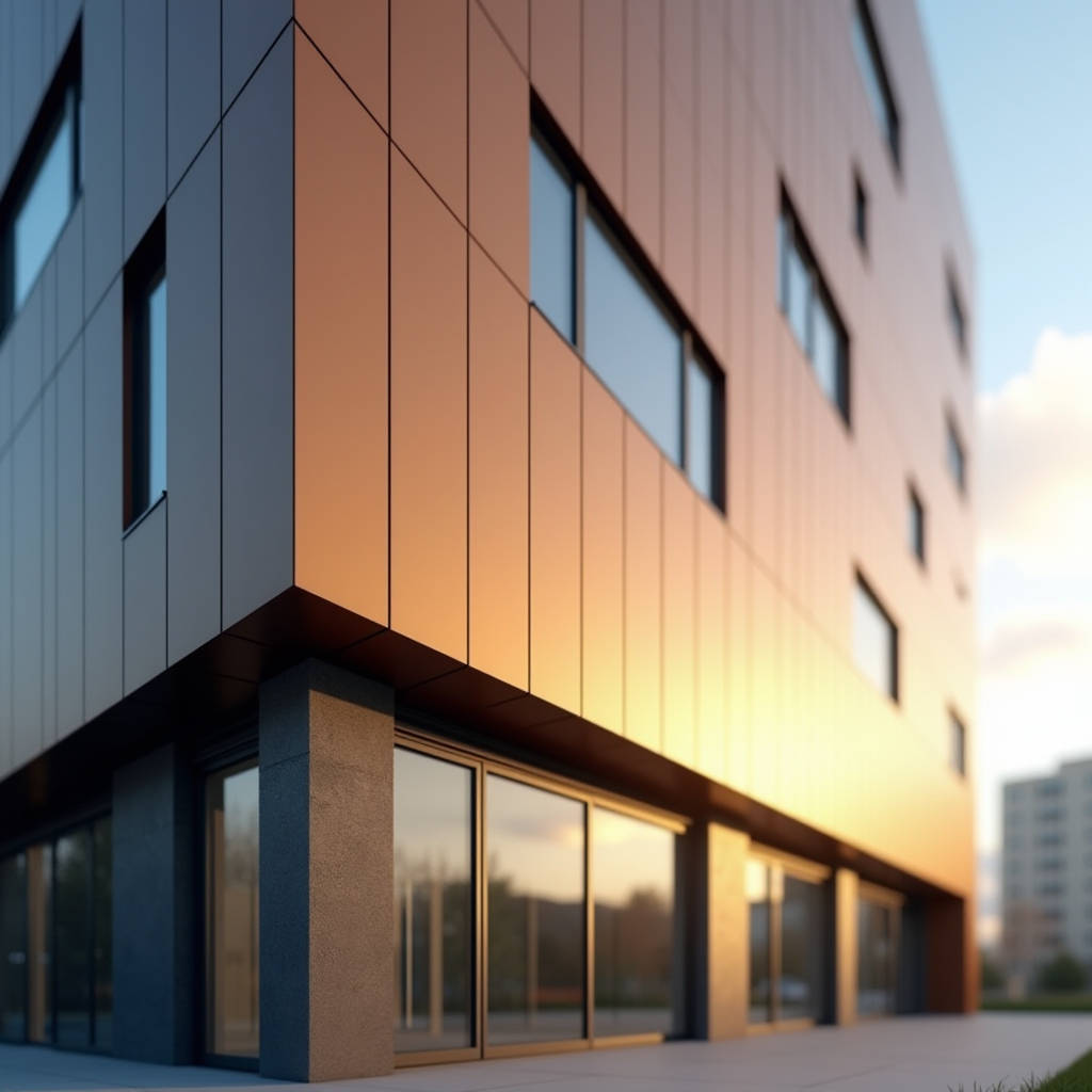
A Ventilated Aluminium Facade operates on a deceptively simple principle: separating the exterior aluminium cladding from the building's structural wall with a continuous air cavity. This cavity, typically 20 to 100 mm deep, drives a chimney effect that expels moisture, reduces thermal bridging, and cuts cooling loads by up to 30% in warm climates. For specifiers and contractors, the real engineering challenge lies not in the concept but in the execution—selecting the right solid aluminium panel gauge, designing a substructure that absorbs thermal movement without buckling, and detailing joints that maintain the cavity's breathability across decades of UV exposure and wind-driven rain. This article focuses on the load-path engineering, material selection, and installation sequencing that determine whether a ventilated aluminium facade performs for 30 years or becomes a liability in five.
How the Air Cavity Actually Works: Physics, Not Marketing
The ventilated cavity behind a Ventilated Aluminium Facade is not a passive void. It is an active thermodynamic engine. Solar radiation heats the aluminium panels, which in turn warm the air in the cavity. The density differential between heated cavity air and cooler ambient air creates a pressure gradient that drives continuous upward airflow. This stack effect removes both solar heat gain and interstitial moisture before either can penetrate the insulation layer or the structural wall.
The cavity width is the single most consequential dimensional decision in the entire system. At 20 mm, airflow resistance is high and the chimney effect is weak. At 50 mm, the system achieves a practical balance between thermal performance and lost floor area. At 100 mm, airflow is robust but the additional standoff increases bracket cantilever moments substantially. The European standard EN 13165 provides thermal conductivity values for the insulation layer, but the cavity ventilation rate itself is governed by fluid dynamics calculations that many specifiers overlook.
A correctly engineered 50 mm cavity with open joints at the base and head of the facade can reduce the temperature of the insulation layer by 15-20°C compared to a sealed system, based on field measurements from multiple mid-rise commercial projects.
Solid Aluminium Panel Selection: Gauge, Alloy, and Flatness
The cladding material in a ventilated system must resist wind loads, thermal cycling, and impact without deforming. Solid aluminium panels—specifically 5005, 5052, or 3003 alloy sheets at 2.0 mm, 2.5 mm, or 3.0 mm thickness—are the industry standard for ventilated facades that demand long-term flatness. Unlike composite products, solid aluminium has no polyethylene core to delaminate, no differential thermal expansion between skin and core, and no fire propagation risk from combustible core materials.
Panel thickness selection follows a straightforward engineering logic. For ground-floor applications and low-wind regions, 2.0 mm solid aluminium with proper stiffener ribs provides adequate span capability. For mid-rise and high-rise elevations where wind pressures exceed 1.5 kPa, 2.5 mm becomes the minimum. At corners, parapets, and edge zones where ASCE 7 or EN 1991-1-4 codes impose higher local pressure coefficients, 3.0 mm panels eliminate the risk of oil-canning and visible distortion.
| Panel Thickness | Typical Max Span (mm) | Wind Load Capacity (kPa) | Recommended Application Zone | Weight (kg/m²) |
|---|---|---|---|---|
| 2.0 mm Solid Aluminium | 600-800 | Up to 1.2 | Ground floor, sheltered elevations | 5.4 |
| 2.5 mm Solid Aluminium | 800-1100 | 1.2-2.0 | Mid-rise, general elevations | 6.75 |
| 3.0 mm Solid Aluminium | 1100-1400 | 2.0-3.5 | High-rise corners, edge zones, parapets | 8.1 |
Alloy choice matters equally. 5005 and 5052 alloys offer superior corrosion resistance in coastal and industrial environments. 3003 provides adequate performance for inland applications at a lower material cost. The temper—typically H14 or H24—determines formability for folded edges and return legs. For ventilated facades with complex geometric panels, 5052-H32 is the preferred specification because it balances bendability with post-forming strength.
Substructure Engineering: The Load Path from Panel to Building
The aluminium substructure of a Ventilated Aluminium Facade is a three-dimensional load-transfer system. Vertical profiles (mullions) carry the dead weight of the panels and transfer it to the building structure through adjustable brackets at each floor level. Horizontal profiles (transoms) resist wind loads and transfer them to the mullions. The brackets themselves must accommodate three axes of adjustment—vertical, horizontal, and depth—to compensate for building tolerances while maintaining the precise cavity dimension.
Thermal expansion is the silent killer of poorly designed substructures. Aluminium expands at approximately 0.024 mm per meter per degree Celsius. A 4-meter mullion subjected to a 60°C seasonal temperature swing will grow by 5.76 mm. If the fixing system does not allow this movement, the resulting stress manifests as bowed panels, popped fasteners, or cracked welds. The solution is a combination of fixed points (typically at mid-span) and sliding points that permit longitudinal movement.
Bracket Thermal Breaks and Condensation Control
Every bracket that bridges the cavity from the structural wall to the aluminium substructure creates a thermal bridge. Without a thermal break—typically a 10-15 mm thick polyamide or PVC isolator pad—condensation forms on the cold side of the bracket inside the cavity. Over time, this moisture corrodes fasteners, saturates insulation, and supports mould growth. The thermal break material must have a thermal conductivity below 0.3 W/mK and sufficient compressive strength to carry the bracket load without creep.
For projects pursuing BREEAM or LEED certification, the thermal bridging calculation (Psi-value) for each bracket type must be submitted as part of the energy modelling. Suppliers like Futeng® provide pre-calculated Psi-values for their standard bracket configurations, which reduces the modelling burden on the design team and accelerates the certification submission.
PVDF Coating Systems: Performance Beyond Colour
The coating on a Ventilated Aluminium Facade panel does more than determine the building's appearance. It is the primary defence against UV degradation, chemical attack, and surface erosion. Polyvinylidene fluoride (PVDF) coatings—applied as a multi-layer system with a total dry film thickness of 30-40 microns—are the benchmark for architectural aluminium.
A complete PVDF system consists of a chromate or chrome-free conversion coating, a primer layer (5-10 microns), and a colour coat (25-30 microns) containing a minimum 70% PVDF resin by weight. The resin ratio is critical: coatings with less than 70% PVDF resin do not meet the requirements of AAMA 2605, the highest performance standard for architectural coatings. Specifiers should request a resin certification from the coating applicator for every batch.
| Coating Standard | Minimum PVDF Resin Content | Accelerated Weathering (QUV) | Colour Retention (10 Years, Florida Exposure) | Typical Warranty |
|---|---|---|---|---|
| AAMA 2605 | 70% | 4000 hours, ΔE ≤ 5 | ΔE ≤ 5 | 20-30 years |
| AAMA 2604 | 50% | 2000 hours, ΔE ≤ 5 | ΔE ≤ 8 | 10-15 years |
| AAMA 2603 | 0% (polyester) | 1000 hours, ΔE ≤ 5 | ΔE ≤ 10 | 5-10 years |
For ventilated facades in coastal environments, the coating specification should include additional salt spray resistance testing per ASTM B117. A minimum of 3000 hours with no blistering, no loss of adhesion, and no creepage beyond 2 mm from the scribe line is a reasonable requirement. The American Architectural Manufacturers Association publishes the full AAMA 2605 test protocol, which should be referenced in every project specification.
Wind Load Engineering for Ventilated Facades
A ventilated cavity introduces pressure equalisation dynamics that differ from sealed curtain wall systems. When wind strikes a building, the external pressure on the cladding surface is partially transmitted into the cavity through the open joints. The degree of pressure equalisation depends on the open area ratio of the joints relative to the cavity volume. A well-designed ventilated facade with 5-10% open joint area can achieve 60-80% pressure equalisation, significantly reducing the net wind load on the panels.
However, this equalisation is not uniform across the entire elevation. Corner zones, ridge zones, and areas adjacent to parapets experience higher peak pressures that do not fully equalise. The design wind load must be calculated per the relevant code—ASCE 7 in North America or EN 1991-1-4 in Europe—with appropriate pressure coefficients for each zone. Panel fixings, mullion spans, and bracket spacing must all be sized for the worst-case zone pressure, not the average.
Fixing Design: Screws, Rivets, and Clips
The connection between the aluminium panel and the substructure is the most stressed interface in the entire system. Three fixing methods dominate: exposed stainless steel screws, concealed aluminium clips, and cassette systems with integrated return legs. Exposed screws are the most economical but create visible fasteners that disrupt the visual plane and require precise alignment. Concealed clip systems, typically fabricated from 1.5-2.0 mm stainless steel, provide a clean aesthetic but demand tighter panel fabrication tolerances—typically ±1.0 mm on folded edges.
All fasteners in a ventilated aluminium facade must be stainless steel, grade 304 as a minimum and grade 316 for coastal or industrial environments. Galvanised steel fasteners will corrode within 3-5 years in the warm, occasionally humid cavity environment, staining the panels and compromising the structural connection.
Fire Performance and Cavity Barriers
The continuous air cavity that makes a Ventilated Aluminium Facade thermally efficient also creates a potential chimney for fire propagation. Building codes in most jurisdictions—including the International Building Code (IBC) and UK Building Regulations Approved Document B—require horizontal and vertical cavity barriers at each floor level and at compartment boundaries.
These barriers must be non-combustible (Euroclass A1 or A2-s1,d0) and must maintain their integrity for the required fire resistance period—typically 60 or 120 minutes. Mineral wool cavity barriers with intumescent strips are the standard solution. The intumescent material expands when exposed to heat, sealing the cavity against flame and hot gas passage. The barrier must be mechanically fixed to the structural wall, not merely friction-fitted, and the fixing detail must account for the full depth of the cavity including the insulation layer.
Solid aluminium panels themselves are non-combustible (Euroclass A1), which simplifies the fire engineering submission compared to systems that use combustible core materials. The ISO 1716 standard defines the test method for determining the gross heat of combustion, and solid aluminium panels consistently report values of zero.
Installation Sequencing and Quality Control
The sequence of installation directly affects the final flatness and alignment of the facade. The correct sequence is: bracket installation and survey, insulation layer, vertical mullions, horizontal transoms, and finally panel hanging. Each step includes a quality control hold point.
After bracket installation, a laser survey must verify that all bracket faces lie within a single plane to a tolerance of ±3 mm over any 3-meter length. Brackets that fall outside this tolerance must be shimmed or replaced. After mullion installation, a second survey checks vertical alignment and straightness. The panels themselves should be inspected for flatness, coating defects, and dimensional accuracy before installation begins.
Panel handling on site is a common source of damage. Solid aluminium panels at 2.5 mm and 3.0 mm are heavy—a 1.2 m × 3.0 m panel at 3.0 mm weighs approximately 29 kg. Manual handling requires two installers, and the panels must be stored vertically on edge-protected racks, not stacked flat. Protective film should remain in place until the panel is fully installed and the adjacent panels are aligned.
Thermal Performance Metrics and Energy Code Compliance
The U-value of a ventilated facade wall assembly is calculated differently from a sealed wall. The ventilated cavity effectively decouples the cladding from the insulation layer, meaning the cladding's thermal resistance is not included in the U-value calculation. The relevant standard is ISO 6946, which provides the methodology for calculating the thermal resistance of building components with ventilated air layers.
A typical ventilated aluminium facade with 120 mm of mineral wool insulation (thermal conductivity 0.035 W/mK) in the cavity achieves a U-value of approximately 0.28 W/m²K. Adding 20 mm of vacuum insulation panel (VIP) behind the mineral wool can reduce this to 0.15 W/m²K, meeting Passive House standards. The cost increment for VIP is significant—approximately €80-120 per square meter—but the reduction in heating and cooling energy can deliver a payback period of 8-12 years in commercial buildings.
Acoustic Performance in Urban Environments
The air cavity in a ventilated facade also functions as an acoustic buffer. Sound waves from traffic, rail, and aircraft must penetrate the aluminium panel, traverse the air cavity, and pass through the insulation layer before reaching the building interior. The mass-air-mass resonance frequency of the system can be tuned by adjusting the cavity depth and the panel mass.
A 2.5 mm solid aluminium panel with a 50 mm cavity and 100 mm of mineral wool typically achieves a weighted sound reduction index (Rw) of 45-48 dB. For buildings adjacent to major roads or rail corridors, increasing the cavity to 100 mm and adding a high-density acoustic barrier behind the insulation can push the Rw above 52 dB. The ISO 10140 series specifies the laboratory measurement procedures for airborne sound insulation of building elements.
Cost Drivers and Value Engineering Without Compromise
The installed cost of a Ventilated Aluminium Facade typically ranges from €180 to €350 per square meter, depending on panel thickness, coating specification, substructure complexity, and site access. The substructure accounts for 35-45% of the total cost, the panels 30-40%, and installation labour 20-30%.
Value engineering efforts that reduce panel thickness below 2.0 mm or substitute polyester coatings for PVDF are false economies. A 2.0 mm panel in a high-wind corner zone will oil-can within the first year, and a polyester coating will chalk and fade within five years in UV-exposed locations. The resulting rectification costs—scaffolding, panel removal, replacement, and reinstallation—typically exceed the initial savings by a factor of three.
Genuine cost optimisation comes from standardising panel sizes to reduce fabrication waste, designing the substructure for efficient bracket spacing that minimises the number of fixings into the structural wall, and selecting a panel module that aligns with the building grid to eliminate half-panels and custom cuts. These decisions must be made during the design development phase, not during procurement.
Specifying a Ventilated Aluminium Facade: The Critical Path
The specification document for a ventilated aluminium facade must address every component in the load path. A specification that focuses only on the panel material and ignores the substructure, fixings, thermal breaks, and cavity barriers will result in a system that looks correct on the shop drawing but performs poorly in service.
The panel specification should reference alloy, temper, thickness, flatness tolerance (maximum 0.5% of the panel diagonal), coating system (AAMA 2605 minimum for exterior applications), and colour consistency (ΔE ≤ 1.0 between batches). The substructure specification should define the profile alloy (typically 6063-T6), the bracket material and thermal break, the fastener grade, and the adjustment range for each axis. The cavity barrier specification must state the fire resistance period, the intumescent type, and the fixing method.
For procurement teams sourcing from international suppliers, verifying factory capability is essential. A supplier with in-house PVDF coating lines, CNC folding equipment, and a documented quality management system reduces the risk of batch inconsistency and delivery delays. Requesting a factory audit or a third-party inspection report from a recognised body provides assurance that the specified materials and processes are actually being used.
The ventilated aluminium facade is a system, not a product. Its long-term performance depends on the engineering of each interface—panel to substructure, substructure to bracket, bracket to building, and cavity to atmosphere. When each of these interfaces is correctly designed, specified, and installed, the result is a building envelope that manages moisture, reduces energy consumption, and maintains its appearance for decades.