Double Skin Aluminium Facade Engineering From Cavity Design to Panel Specification
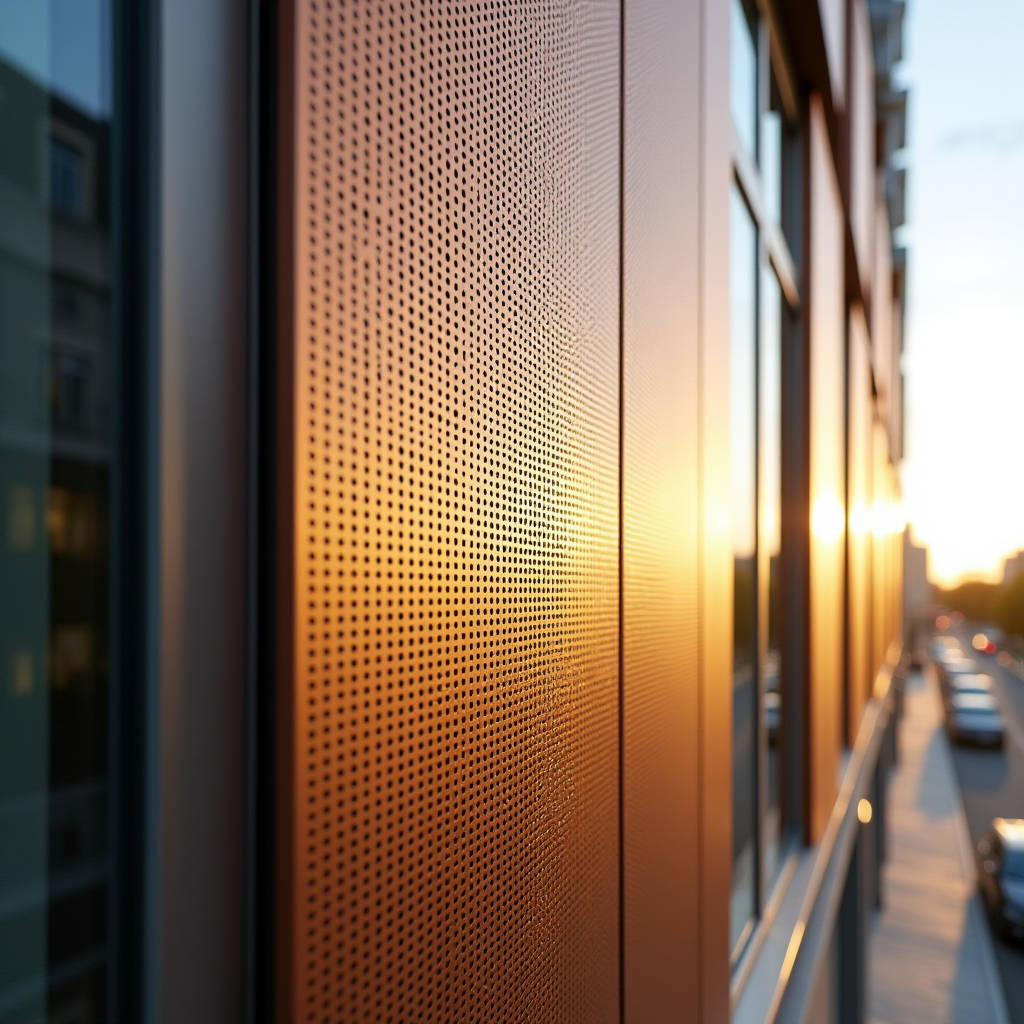
When a building specification calls for a Double Skin Aluminium Facade, the conversation shifts from simple cladding to engineered thermal performance. A double skin system places two aluminium facade layers with a precisely calculated intermediate cavity, creating a ventilated buffer zone that actively manages heat gain, acoustic transmission, and moisture migration. Unlike single-layer rainscreen assemblies, a Double Skin Aluminium Facade transforms the building envelope into a dynamic thermal moderator. For contractors and facade engineers, the critical question is not whether the concept works, but how to detail the aluminium components so the cavity performs as modeled. This means selecting the right solid aluminium panel thickness, specifying cavity widths that support natural stack effect ventilation, and integrating maintenance access without compromising the thermal break. The following sections break down the engineering logic, material specifications, and installation sequencing that separate a well-executed double skin from a costly thermal bridge.
How a Double Skin Aluminium Facade Functions as a Thermal Buffer
The operating principle behind a Double Skin Aluminium Facade relies on a ventilated air cavity sandwiched between an outer aluminium rainscreen and an inner building envelope layer. During winter months, the cavity traps solar radiation, preheating intake air and reducing the mechanical heating load on the building core. In summer, the same cavity vents hot air upward through natural convection, pulling cooler ambient air from intake openings at the base of the facade. This stack effect, driven purely by thermal buoyancy, means the outer aluminium skin absorbs direct solar gain and dissipates it before that energy reaches the interior conditioned space.
The cavity depth is not arbitrary. For naturally ventilated double skin systems, cavity widths typically range from 600mm to 900mm to allow sufficient airflow cross-section. Mechanically ventilated systems can operate with narrower cavities, sometimes as tight as 200mm, but these require fan-assisted air movement that adds operational energy cost. The choice between natural and mechanical ventilation directly impacts the structural subframe design, because wider cavities demand deeper bracket projections and heavier dead loads on the primary structure. Solid aluminium panels at 2.5mm or 3.0mm thickness, finished with PVDF fluoropolymer coatings, provide the outer skin rigidity needed to span these bracket distances without oil-canning or deflection under wind suction.
Thermal modeling for a Double Skin Aluminium Facade must account for the emissivity of the aluminium panel rear surface. A standard mill-finish aluminium back face has an emissivity of approximately 0.05 to 0.10, reflecting radiant heat back into the cavity rather than absorbing it. This low-emissivity characteristic is inherent to aluminium and does not degrade over time, unlike applied low-e films on glass. When combined with a ventilated cavity, the aluminium outer skin can reduce peak cooling loads by 18% to 25% compared to a single-skin curtain wall with equivalent glazing ratios, based on field measurements from multiple mid-rise commercial projects in temperate climate zones.
Material Selection: Solid Aluminium Panels for the Outer Skin
The outer layer of a Double Skin Aluminium Facade faces the harshest conditions: direct UV exposure, wind-driven rain, thermal cycling, and in coastal environments, chloride-laden air. Solid aluminium panels, manufactured from AA 3003 or AA 5005 alloy sheets at 2.0mm, 2.5mm, or 3.0mm thickness, are the standard substrate for this application. The alloy selection matters. AA 3003 offers excellent formability for complex panel geometries and perforation patterns. AA 5005 provides higher tensile strength and better corrosion resistance in marine exposures, making it the preferred choice for coastal double skin projects.
Coating specification is equally critical. A three-coat PVDF system, typically comprising a primer, a colour coat, and a clear topcoat with total dry film thickness of 30-35 microns, delivers the weatherability required for a facade element that may remain in place for 30 to 50 years. The clear topcoat in a 70% PVDF resin system contains UV-stabilising additives that protect the pigment layer from chalking and fading. For Double Skin Aluminium Facade projects in the Middle East or Southeast Asia, where solar irradiance exceeds 1000 W/m² at peak, a four-coat system with a barrier primer adds an extra layer of corrosion protection between the aluminium substrate and the colour coat.
Perforated aluminium panels deserve special attention in double skin design. When the outer skin incorporates perforations, the open area ratio directly affects cavity ventilation rates, daylight admission, and the visual transparency of the facade. Open area ratios between 20% and 40% are common for architectural double skin applications. Below 20%, the perforations contribute little to cavity ventilation and serve primarily as a visual feature. Above 40%, the panel's structural stiffness decreases measurably, requiring thicker gauge material or additional stiffener ribs welded to the panel rear face. A 2.5mm solid aluminium panel with 25% open area and 8mm diameter perforations on a staggered 15mm pitch can span 1200mm between supports without visible deflection, provided the panel edges are brake-formed with 25mm return legs.
Cavity Design: Ventilation Strategy and Structural Integration
The cavity between the two facade layers is where the engineering of a Double Skin Aluminium Facade succeeds or fails. Three ventilation strategies dominate current practice: natural ventilation with operable intake and exhaust dampers, mechanically assisted ventilation using cavity fans, and sealed cavity systems that function as a thermal buffer without active airflow. Each strategy imposes different requirements on the aluminium subframe and panel joint detailing.
Natural ventilation relies on the stack effect. The cavity must be continuous vertically, with intake openings at the lowest floor level and exhaust openings at the roof or topmost floor. The intake and exhaust cross-sectional areas should each equal at least 0.5% of the total facade area served, though 1.0% is recommended for buildings taller than 30 metres where wind pressure differentials can overcome thermal buoyancy. The aluminium subframe within the cavity must not obstruct airflow. Vertical mullions should be oriented parallel to the airflow direction, and horizontal transoms should be perforated or spaced to allow air passage. This means the structural grid for the outer skin often differs from the inner skin grid, adding complexity to bracket design and anchor point coordination.
Mechanically assisted systems use inline axial fans installed at cavity exhaust points to maintain airflow regardless of external wind conditions. These systems allow narrower cavities and more consistent thermal performance, but they introduce ongoing energy consumption and maintenance requirements. The aluminium panel joints in mechanically ventilated cavities must be sealed more tightly than in naturally ventilated systems, because fan-induced pressure differentials can draw moisture through open joints into the cavity. EPDM gaskets at panel perimeters, rated for continuous service temperatures from -40°C to 120°C, provide the necessary seal without compromising the drained-and-ventilated rainscreen principle.
The sealed cavity approach, sometimes called a closed cavity facade, eliminates external air exchange entirely. The cavity is pressurised with dry, filtered air to prevent condensation on the inner glass layer. This strategy demands the highest standard of aluminium panel joint sealing and places greater thermal stress on the outer skin, because solar heat absorbed by the aluminium panels cannot be vented. For sealed cavity Double Skin Aluminium Facade projects, panel coatings must withstand sustained surface temperatures that can reach 80°C to 90°C on dark-coloured panels under peak solar load. PVDF coatings maintain colour stability and film integrity at these temperatures, whereas polyester-based coatings begin to show gloss reduction and chalking within 5 to 7 years under equivalent conditions.
Acoustic Performance: The Overlooked Advantage
A Double Skin Aluminium Facade provides measurable acoustic attenuation that single-skin cladding systems cannot match. The two separated layers, combined with the air cavity, create a mass-air-mass resonance system that reduces sound transmission across a broad frequency range. Laboratory testing per ISO 10140-2 shows that a double skin facade with 3.0mm solid aluminium outer panels, a 600mm ventilated cavity, and a standard inner curtain wall achieves a weighted sound reduction index Rw of 48 to 52 dB, depending on cavity absorption treatment. This compares to Rw 35 to 38 dB for a single-skin aluminium rainscreen over the same inner wall construction.
The acoustic benefit is particularly relevant for buildings on high-traffic urban sites, near airports, or adjacent to rail corridors. Adding acoustic absorption material to the cavity rear face of the outer aluminium panels further improves performance. Perforated aluminium panels with mineral wool or melamine foam absorbers bonded to the rear face can increase the sound absorption coefficient αw to 0.85 or higher, effectively turning the outer skin into a broadband sound absorber. The perforation pattern, open area ratio, and absorber thickness must be tuned to the target frequency range. For traffic noise, which peaks between 500 Hz and 2000 Hz, a 50mm thick mineral wool absorber behind a 25% open area perforated aluminium panel delivers optimal attenuation.
Contractors should note that acoustic performance depends on airtight perimeter sealing where the double skin meets floor slabs, columns, and the roof. Flanking sound transmission through gaps at these interfaces can reduce the field-measured sound insulation by 5 to 8 dB compared to laboratory values. Aluminium flashing and EPDM gaskets at every floor-level cavity closure are essential detailing points that are often overlooked in shop drawings.
Wind Load Engineering for Double Skin Systems
Wind load analysis for a Double Skin Aluminium Facade differs from single-skin cladding in one critical respect: the outer skin experiences wind pressures on both its exterior and interior faces. The cavity pressure, influenced by external wind, ventilation openings, and stack effect, can be positive or negative relative to the exterior pressure. This means the net pressure differential across the outer aluminium panel is not simply the external wind pressure; it is the difference between external pressure and cavity pressure at any given moment.
ASCE 7 and EN 1991-1-4 provide methodologies for calculating cavity pressures in double skin facades. The cavity pressure coefficient Cpc depends on the ratio of opening areas on the windward and leeward faces, the cavity volume, and the building geometry. For a naturally ventilated double skin with uniform intake and exhaust openings, Cpc typically ranges from -0.2 to +0.3 of the external pressure coefficient Cpe. This means the net pressure on the outer skin is approximately 70% to 120% of the external wind pressure, depending on wind direction and opening configuration. The aluminium panel thickness, stiffener layout, and fixing centres must be designed for the worst-case net pressure scenario, which usually occurs when wind is perpendicular to the facade and cavity vents on the windward face are open.
Solid aluminium panels at 3.0mm thickness, with 6063-T6 aluminium stiffener profiles welded or adhered to the rear face at 600mm centres, can typically resist design wind pressures up to 3.0 kPa with deflection limited to span/180. For high-rise projects in cyclone or hurricane-prone regions, where design wind pressures can exceed 5.0 kPa, panel thickness may need to increase to 4.0mm and stiffener spacing reduced to 400mm. These parameters must be verified by structural calculation specific to the project's wind tunnel test data or code-prescribed pressure coefficients.
Installation Sequencing and Tolerances
The installation of a Double Skin Aluminium Facade follows a logical sequence that must be coordinated with the main building structure and interior fit-out. The inner skin, typically a unitised curtain wall or stick-built glazing system, is installed first and made weathertight. This allows interior works to proceed while the outer skin installation continues. The aluminium support brackets for the outer skin are anchored to the primary structure through the inner skin, requiring precise coordination of bracket locations with the inner skin mullion and transom grid.
Bracket installation tolerances are tighter for double skin systems than for single-skin cladding. A ±3mm tolerance in bracket position at the inner skin face translates to a larger deviation at the outer skin plane, especially when the cavity depth exceeds 600mm. The angular error magnifies with distance: a 1mm misalignment at the bracket base over a 700mm projection creates a 3mm to 4mm deviation at the outer panel fixing point. To manage this, adjustable brackets with slotted connections in two or three axes are standard practice. Stainless steel grade 316 brackets with serrated contact surfaces prevent slippage under dead load and wind cycling.
Panel installation proceeds from the bottom of the building upward, with each row of aluminium panels supported by the row below through interlocking horizontal joints. This stacking method transfers the dead load of each panel to the panels beneath it, reducing the load on individual brackets. Vertical expansion joints at 10-metre to 15-metre intervals accommodate thermal movement of the aluminium panels. A 3.0mm thick aluminium panel 3 metres long will expand approximately 2.0mm over a 50°C temperature range, based on the aluminium thermal expansion coefficient of 23 × 10⁻⁶ /K. Joint design must accommodate this movement without binding or opening gaps that compromise weathertightness.
Comparative Cost Drivers in Double Skin Aluminium Facade Projects
The cost of a Double Skin Aluminium Facade is influenced by multiple interrelated factors: cavity depth, ventilation strategy, panel thickness, coating specification, and perforation complexity. The table below provides indicative cost comparisons based on current industry data for mid-rise commercial projects in temperate climate zones. Figures are expressed as percentage of a baseline single-skin aluminium rainscreen system.
| System Configuration | Material Cost Index | Installation Labour Index | Total Installed Cost Index | Typical Payback Period (Energy Savings) |
|---|---|---|---|---|
| Single-Skin Aluminium Rainscreen (Baseline) | 100 | 100 | 100 | N/A |
| Double Skin, Natural Ventilation, 600mm Cavity, 2.5mm Solid Aluminium | 175 - 195 | 140 - 160 | 160 - 180 | 6 - 9 years |
| Double Skin, Mechanical Ventilation, 300mm Cavity, 2.5mm Solid Aluminium | 190 - 210 | 130 - 150 | 165 - 185 | 8 - 12 years |
| Double Skin, Sealed Cavity, 200mm Cavity, 3.0mm Solid Aluminium | 200 - 225 | 150 - 170 | 180 - 205 | 10 - 15 years |
| Double Skin, Natural Ventilation, 900mm Cavity, 3.0mm Perforated Panels (25% Open Area) | 210 - 240 | 160 - 185 | 190 - 220 | 7 - 10 years |
Cost indices are approximate and vary with project location, building height, and local labour rates. The payback period calculations assume energy cost savings from reduced HVAC loads in a temperate climate with both heating and cooling seasons. Projects in extreme climates, where heating or cooling dominates year-round, may see shorter payback periods due to higher baseline energy consumption. For procurement managers evaluating supplier options, manufacturers such as Futeng® that offer integrated panel fabrication and bracketry systems can reduce coordination costs by 8% to 12% compared to sourcing panels and brackets from separate suppliers.
Maintenance Access and Long-Term Durability
A Double Skin Aluminium Facade must provide safe, practical access for cleaning, inspection, and maintenance of the cavity interior. The outer skin typically incorporates access panels or operable sections at each floor level, sized to allow a maintenance worker to reach into the cavity with cleaning equipment. For cavities wider than 600mm, full walkable access may be required, with aluminium grating walkways supported on the cavity subframe. These walkways must be designed for a live load of 2.5 kPa per EN 1991-1-1, with slip-resistant surfaces and guardrail attachment points.
The PVDF coating on solid aluminium panels requires periodic cleaning to maintain its appearance and performance. In most urban environments, rainfall provides sufficient natural cleaning for vertical panel surfaces. In sheltered locations or areas with high particulate pollution, manual washing at 12 to 24-month intervals is recommended. Cleaning should use pH-neutral detergents applied with soft brushes or sponges; abrasive cleaners and high-pressure water jets above 50 bar can damage the PVDF coating surface and should be avoided. The coating manufacturer's maintenance guidelines, typically aligned with AAMA 609.1 and 610.1 standards, provide specific cleaning procedures and approved detergent formulations.
Corrosion protection for aluminium components within the cavity deserves particular attention. Although aluminium naturally forms a protective oxide layer, the cavity environment can be more aggressive than the exterior atmosphere. Condensation cycles, combined with any airborne contaminants drawn into the cavity, can accelerate localised corrosion at cut edges, fastener holes, and bracket contact points. All aluminium components within the cavity should be finished with a minimum 60-micron polyester powder coating or a chromate conversion coating per ISO 7599. Stainless steel fasteners, grade 316 for coastal or industrial environments, prevent galvanic corrosion at panel-to-bracket connections.
Fire Performance and Cavity Barriers
Fire safety in a Double Skin Aluminium Facade centres on preventing vertical fire spread through the cavity. The ventilated cavity, essential for thermal performance, also creates a potential chimney for flames and hot gases if a fire breaches the inner or outer skin. Building regulations in most jurisdictions, including the International Building Code and relevant European national standards, require cavity barriers at each floor level and at vertical intervals not exceeding 10 metres.
Aluminium cavity barriers, comprising intumescent strips bonded to aluminium support angles, expand when exposed to temperatures above 150°C, sealing the cavity cross-section. The aluminium support must maintain structural integrity for the required fire resistance period, typically 60 or 90 minutes depending on building height and occupancy classification. The intumescent material must be tested in the specific cavity configuration, including the ventilation opening geometry, because the expansion behaviour differs between open and partially enclosed cavities. Test standards such as ASTM E2307 and EN 1364-6 provide methodologies for assessing fire performance of facade cavity barriers.
The aluminium panels themselves are non-combustible, classified as A1 per EN 13501-1 or Class A per ASTM E84, with a melting point of approximately 660°C. This is a significant advantage over composite panels with polyethylene cores, which can contribute to fire spread. However, the panel coating system, gaskets, and any acoustic insulation within the cavity must also be evaluated for reaction-to-fire classification. Mineral wool insulation with a melting point above 1000°C and classified A1 is the standard choice for cavity acoustic treatment in double skin systems where fire performance is a priority.
Specifying a Double Skin Aluminium Facade: Key Documentation Points
A robust specification for a Double Skin Aluminium Facade must address the interfaces between the outer aluminium skin, the cavity, and the inner envelope. The following points should be explicitly detailed in tender documents and reviewed during shop drawing approval:
- Panel alloy and temper: Specify AA 3003-H14 or AA 5005-H14 for standard applications. AA 5005-H34 for marine environments. Minimum thickness 2.0mm, with 2.5mm or 3.0mm required for panels exceeding 1.0m² face area or in high wind zones.
- Coating system: Three-coat PVDF, 70% resin minimum, total DFT 30-35 microns, tested per AAMA 2605. Colour range and gloss level to be confirmed by physical sample approval, not digital renderings.
- Cavity ventilation: Define ventilation strategy (natural, mechanical, or sealed), intake and exhaust opening areas as percentage of served facade area, and any required insect mesh or bird mesh at openings.
- Bracket system: Stainless steel grade 316, three-axis adjustability, serrated contact surfaces, thermal break pads at connections to the inner skin to prevent thermal bridging.
- Cavity barriers: Location at each floor level, intumescent material specification, support bracket fire resistance rating, and integration with the aluminium panel joint pattern.
- Acoustic treatment: If required, specify absorber material, thickness, density, and fixing method to the rear face of outer aluminium panels. Include perforation pattern and open area ratio for perforated panels.
- Access and maintenance: Location and size of access panels, walkway load rating, and any permanent anchorage points for rope access or building maintenance units.
Shop drawing review should verify that the panel joint detailing accommodates the calculated thermal movement, that bracket centres match the structural engineer's wind load calculations, and that the cavity barrier locations align with the fire engineer's compartmentation strategy. Coordination between the facade contractor, structural engineer, fire engineer, and acoustic consultant is essential, because changes to any one system ripple through the others.
The Double Skin Aluminium Facade represents a significant investment in building performance. When the aluminium panel specification, cavity ventilation strategy, and structural subframe are engineered as an integrated system rather than a collection of separate components, the result is a facade that delivers measurable reductions in energy consumption, interior noise levels, and long-term maintenance costs. The engineering effort concentrates at the interfaces: where the bracket meets the inner skin, where the panel joint meets the cavity airflow, and where the cavity barrier meets the fire strategy. Getting these interfaces right, documented in clear specifications and verified through mock-up testing, is the difference between a double skin that performs as modeled and one that becomes a costly lesson in facade physics.