Unitized Aluminum Curtain Wall Structural Logic and Procurement Strategy for High Rise Projects
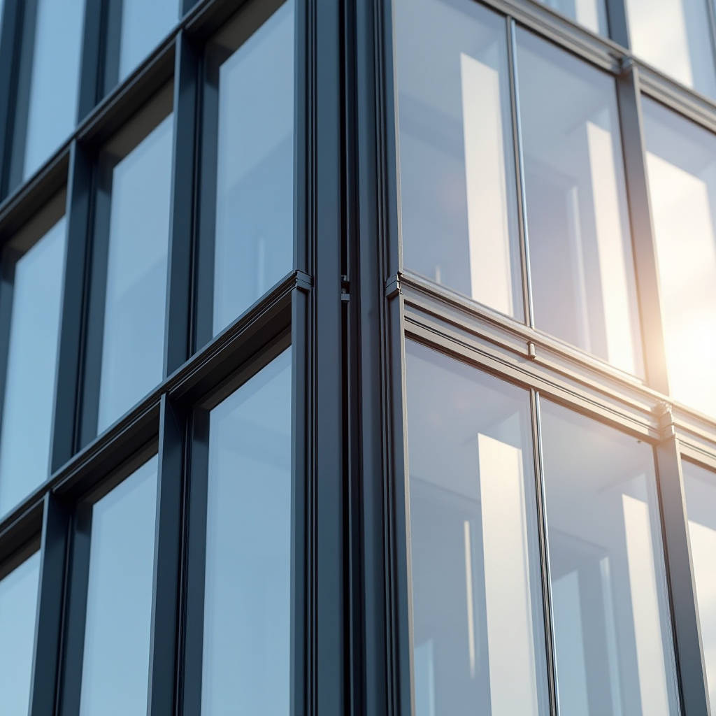
When a general contractor evaluates facade strategies for a 40-story commercial tower, the decision between stick-built and unitized systems shapes the entire construction schedule. Unitized Aluminum Curtain Wall technology has shifted from a premium option to a practical necessity on projects where on-site labor is scarce, weather windows are tight, and quality consistency is non-negotiable. The core premise is straightforward: entire facade modules—aluminum frames, glass, gaskets, spandrel panels, and insulation—are assembled and glazed inside a factory, then shipped to the site and hung from the floor slabs in a single crane lift. This approach eliminates the chaos of field cutting, reduces scaffolding dependency, and allows interior trades to begin work within days rather than weeks. Yet the decision to go unitized carries implications that extend far beyond installation speed. Thermal performance, long-term water management, seismic behavior, and the compatibility of solid aluminum cladding panels within the unitized grid all demand careful engineering scrutiny. This article examines the structural and operational logic behind unitized facades, with particular attention to how solid aluminum infill panels perform in these systems, and what procurement teams need to verify before committing to a unitized strategy.
What Separates Unitized From Stick-Built Curtain Wall
The fundamental distinction lies in where the work happens. A stick-built curtain wall arrives at the job site as a kit of extruded aluminum mullions, transoms, pressure plates, and gaskets. Crews assemble the frame piece by piece on the building exterior, often working from scaffolding or mast climbers. Glass is then installed from the outside, and each joint is sealed in the field. A unitized system reverses this logic. Each module—typically one floor tall and spanning 1.5 to 2.0 meters in width—is fully fabricated in a controlled factory environment. The frame is machined with CNC precision, gaskets are seated under consistent pressure, and glazing is applied before the unit ever leaves the shop floor.
This factory-centric approach produces several downstream effects. First, quality control shifts from the unpredictable conditions of a construction site to a manufacturing line where temperature, humidity, and cleanliness are regulated. Second, the critical path on site shortens dramatically. A stick-built crew might take four to six months to enclose a 30-story tower; a unitized crew can achieve the same in eight to twelve weeks. Third, the skill profile changes. Unitized installation requires fewer highly specialized glaziers on site, which matters in markets where experienced facade labor commands premium wages or simply is not available in sufficient numbers.
However, the unitized approach is not simply "stick-built but faster." The structural logic differs. In a stick system, mullions run continuously past floor slabs, and the entire frame shares loads across multiple anchor points. A unitized system typically uses a split-mullion design—each module has its own vertical framing members that interlock with adjacent units through a male-female or female-female mating profile. Load transfer happens at discrete connection points at each floor level. This means the anchor engineering, slab edge tolerances, and inter-unit joint design become far more critical than in stick construction.
Structural Load Paths in Unitized Systems
Understanding how loads travel through a Unitized Aluminum Curtain Wall is essential for anyone specifying or procuring these systems. Each unit is independently supported at the floor slab, typically through a pair of adjustable brackets—one fixed, one sliding—that accommodate vertical movement and horizontal adjustment. Dead load (the weight of the unit itself) transfers directly downward through these brackets into the slab edge. Wind load travels a different path: positive and negative wind pressures on the facade face are resisted by the aluminum frame, transmitted through the interlocking vertical joints to adjacent units, and ultimately delivered to the slab anchors at each floor level.
The split-mullion joint is the system's most technically demanding feature. Two adjacent units meet at a vertical joint where one unit carries a male profile (a projecting tongue) and the other a female profile (a receiving channel). These profiles interlock but must allow for differential movement between units. The joint must accommodate three types of movement simultaneously: inter-story drift during seismic or wind events, thermal expansion and contraction of the aluminum framing, and live-load deflection of the floor slabs. A well-designed unitized joint uses a multi-chamber gasket system that maintains an air and water seal across a movement range of ±10 to ±25 mm, depending on the specific system and seismic requirements.
Seismic performance deserves particular attention. In high-seismic zones, the inter-unit joint must prevent the units from binding or disengaging during a lateral event. The industry standard for seismic testing is AAMA 501.4 and AAMA 501.6, which subject full-scale mockups to simulated inter-story drift cycles. Specifiers should verify that the proposed unitized system has passed these tests at the drift ratios required by the project's structural engineer—typically 0.015 to 0.025 radians for commercial buildings in seismic categories D and above.
Thermal Performance and Condensation Control
The thermal break in a unitized aluminum frame is not a secondary feature; it is the primary defense against energy loss and interior condensation. In a thermally broken system, the aluminum profile is split into interior and exterior halves, connected by a low-conductivity polyamide or polyurethane strut. This strut—typically 24 to 42 mm in depth depending on climate zone requirements—interrupts the thermal bridge that would otherwise allow heat to flow directly from the warm interior to the cold exterior.
When evaluating a unitized system's thermal performance, three metrics matter. The first is the U-factor of the overall assembly, measured in W/m²·K. A high-performance unitized wall with double-glazed low-E insulating glass and a 30 mm polyamide thermal break can achieve U-factors in the range of 1.4 to 1.8 W/m²·K. Triple-glazed configurations push this below 1.0 W/m²·K. The second metric is the Condensation Resistance Factor (CRF), governed by AAMA 1503. A CRF above 55 is generally acceptable for office buildings; above 65 is required for high-humidity occupancies like hospitals or indoor pools. The third is the frame's thermal transmittance (Uf value) in isolation, which determines whether the system meets the increasingly stringent energy codes in jurisdictions that have adopted ASHRAE 90.1-2022 or the IECC 2024.
A practical concern that often surfaces during construction is the interface between the unitized frame and spandrel areas. Where vision glass gives way to opaque spandrel panels, the back-pan insulation must be carefully detailed to prevent thermal bypass. Solid aluminum cladding panels used as spandrel covers require a continuous insulation layer behind them, typically mineral wool or rigid foam board, with the vapor barrier positioned on the warm side of the assembly to prevent interstitial condensation. The aluminum spandrel panel itself must be vented and drained to the exterior to equalize pressure and allow any incidental moisture to escape.
Solid Aluminum Cladding Panels in Unitized Grids
While unitized systems are often associated with all-glass facades, the reality on most commercial projects is that 30 to 50 percent of the facade area consists of opaque spandrel zones and column covers. This is where solid aluminum cladding panels enter the equation. Unlike aluminum composite material (ACM), solid aluminum panels are manufactured from a single sheet of alloy—typically 3003-H14 or 5005-H34—in thicknesses of 2.0 mm, 2.5 mm, or 3.0 mm. They are formed to shape on CNC folding equipment, reinforced with welded aluminum stiffeners on the rear face, and finished with a PVDF (polyvinylidene fluoride) coating system applied to a minimum dry film thickness of 30 microns for a three-coat system or 40 microns for a four-coat system.
The integration of solid aluminum panels into a unitized grid requires coordination between the panel fabricator and the unitized wall system supplier. The panels must be dimensioned to fit within the module's aluminum perimeter frame, with edge details that allow for thermal movement without causing oil-canning or gasket disengagement. A typical detail uses a perimeter extrusion that captures the panel edge while allowing ±3 mm of movement. The panel's rear stiffeners must be positioned so they do not interfere with the unitized frame's horizontal transoms or the anchor brackets at the slab line.
From a procurement standpoint, the key specification to verify is the PVDF coating system's compliance with AAMA 2605, the highest performance standard for architectural coatings on aluminum. AAMA 2605 requires the coating to pass a 10-year South Florida exposure test with a color change (Delta E) of no more than 5 units and a gloss retention of at least 50 percent. For projects in coastal or industrial environments, the specification should also require a chrome-based pretreatment or an approved chrome-free alternative that meets the corrosion resistance requirements of ASTM B117 salt spray testing for a minimum of 3,000 hours.
Suppliers like Futeng® have developed specialized solid aluminum panel systems that are pre-engineered for compatibility with major unitized curtain wall platforms, reducing the coordination burden on the design team and ensuring that the panel-to-frame interface has been tested as a complete assembly.
Water Management: Pressure-Equalized vs. Drained Systems
Water penetration is the most common failure mode in curtain wall systems, and the unitized approach offers both advantages and vulnerabilities in this regard. The dominant water management strategy in modern unitized walls is the pressure-equalized rain-screen principle. The concept is that the outer face of the wall is designed as a rain screen that blocks the majority of water, while the cavity behind it is vented to the exterior so that the air pressure in the cavity equals the exterior wind pressure. When pressures are equalized, there is no pressure differential to drive water through the joints.
A properly executed pressure-equalized unitized system has three lines of defense. The primary line is the outer seal—typically a wet seal or compression gasket at the exterior face of the inter-unit joint. The secondary line is the pressure-equalization chamber itself, which is vented to the exterior through strategically placed openings. The tertiary line is the interior air seal, which prevents conditioned interior air from reaching the cavity and causing condensation. The drainage path must be continuous from top to bottom of each unit, with horizontal transoms sloped or designed with internal gutters that direct water to the vertical mullions and then out through weep holes at each floor level.
One vulnerability specific to unitized systems is the horizontal joint between stacked units. At each floor level, the joint between the unit above and the unit below must accommodate slab deflection, thermal movement, and construction tolerances while maintaining a watertight seal. The typical detail uses a horizontal sill extrusion on the lower unit that incorporates a dam and a drainage channel, with the upper unit's head extrusion lapping over it. The gap is sealed with a combination of a silicone gasket and a continuous EPDM membrane that is field-applied after the units are hung. Field testing per AAMA 501.2 at a rate of 5 gallons per hour per square foot is standard practice to verify that the installed system meets the specified water penetration resistance.
Installation Logistics and Crane Strategy
The speed advantage of a Unitized Aluminum Curtain Wall is real, but it depends entirely on logistics planning. Each unit for a typical high-rise might weigh between 250 and 500 kg, depending on the glass configuration and the proportion of solid aluminum spandrel panels. Units are typically delivered to the site in sequence-loaded trailers, with each unit labeled by floor and grid position. The site team must have a laydown area large enough to stage one to two days of installation—usually 30 to 60 units—and a crane or hoist dedicated to lifting units into position.
The installation sequence generally follows one of two patterns. In the "floor-by-floor" method, all units for a given floor are installed before moving to the next floor above. This allows the floor slab to be enclosed quickly, which is the priority when interior trades need early access. In the "stack" method, vertical columns of units are installed from bottom to top in a single column, which can be faster when the crane is positioned at a fixed location and the building footprint is compact. The choice between these methods depends on the crane's reach, the building geometry, and the general contractor's schedule for interior work.
A practical consideration that project teams sometimes overlook is the tolerance stack-up at the slab edge. Unitized systems rely on the concrete slab edge being within a specified tolerance—typically ±10 mm in plan position and ±5 mm in elevation per floor. If the slab edges are out of tolerance, the anchor brackets may not have sufficient adjustment range, and the units will not hang plumb. This forces costly remedial work: either grinding down high spots on the concrete or shimming low spots with steel plates and non-shrink grout. A pre-installation survey of the slab edges using a total station or laser scanner is a modest investment that can prevent days of delay.
Comparing Coating Systems for Aluminum Facade Components
The longevity of the aluminum elements in a unitized facade—both the extruded frame and the solid cladding panels—depends heavily on the coating system specified. The table below compares the three coating technologies most commonly encountered in commercial facade specifications.
| Property | PVDF (AAMA 2605) | FEVE Fluoropolymer | Polyester Powder (AAMA 2604) |
|---|---|---|---|
| Resin System | 70% PVDF / 30% Acrylic | Fluoroethylene Vinyl Ether | Super-Durable Polyester |
| Dry Film Thickness | 30-40 microns (3-4 coat) | 35-45 microns | 60-80 microns |
| Gloss Retention (10 yr) | >50% | >60% | 30-50% |
| Color Stability (ΔE, 10 yr) | <5 | <4 | <7 |
| Chalk Resistance | Rating 8+ (ASTM D4214) | Rating 8+ | Rating 6-7 |
| Salt Spray (ASTM B117) | 3,000+ hours | 4,000+ hours | 1,500-2,000 hours |
| Typical Application | Premium commercial facades | Coastal, high-corrosion zones | Mid-range commercial |
| Relative Cost Index | 1.00 (baseline) | 1.15-1.30 | 0.65-0.80 |
For most commercial projects, PVDF conforming to AAMA 2605 represents the optimal balance of cost, durability, and color consistency. FEVE fluoropolymer coatings offer marginally better gloss retention and corrosion resistance, which may justify the premium on coastal projects within 500 meters of breaking surf. Polyester powder coatings meeting AAMA 2604 are suitable for interior applications or low-rise buildings in mild climates, but they lack the long-term chalk and fade resistance required for high-rise facades that are difficult and expensive to repaint.
Cost Drivers and Procurement Strategy
The unitized approach carries a higher upfront cost than stick-built construction—typically 15 to 30 percent more per square meter of facade area, depending on the project's scale, location, and complexity. However, the total installed cost equation must account for factors that unitized construction reduces or eliminates: scaffolding duration, on-site glazing labor, field sealant application, and general conditions overhead during the enclosure phase. On projects where the schedule savings translate to earlier occupancy and revenue generation, the unitized premium can be fully offset by the reduced financing and general conditions costs.
The cost breakdown for a unitized facade module typically allocates 35 to 45 percent to the aluminum framing (extrusions, thermal breaks, gaskets, and hardware), 25 to 35 percent to the glazing (depending on whether the glass is clear, low-iron, or incorporates high-performance coatings), 10 to 15 percent to spandrel panels (solid aluminum or other opaque materials), and the remainder to engineering, testing, transportation, and installation. Solid aluminum spandrel panels with PVDF coating generally add $80 to $150 per square meter of panel area, depending on thickness, stiffener complexity, and finish requirements.
From a procurement perspective, the critical decision is whether to engage a single-source supplier who provides both the unitized framing system and the solid aluminum cladding panels, or to separate the contracts and manage the interface in-house. The single-source approach reduces coordination risk and ensures that the panel-to-frame interface has been tested. The separate-contract approach can yield cost savings on the panel package but requires the design team to take full responsibility for the interface detailing and the general contractor to manage two separate supply chains. For projects over 10,000 square meters of facade area, the single-source approach is generally the lower-risk path.
Testing and Mockup Requirements
No unitized facade should proceed to production without a full-scale performance mockup. The industry reference for testing methodology is ASTM E283 for air infiltration, ASTM E331 for water penetration under static pressure, and ASTM E1105 for water penetration under dynamic pressure. The mockup should be at least two modules wide and two stories tall to capture the critical inter-unit joints in both directions. Testing should be conducted at an accredited laboratory such as those recognized by the American Architectural Manufacturers Association (AAMA).
The testing sequence follows a logical progression. Air infiltration is tested first, as air leakage can mask water leakage. The specimen is subjected to a pressure differential of 300 Pa (6.24 psf), and the allowable air leakage rate is typically 1.5 L/s·m² or less. Water penetration is tested next at a static pressure of 20 percent of the design wind pressure, with a minimum of 300 Pa. Dynamic water testing adds a wind generator to simulate gusting conditions. Finally, structural testing per ASTM E330 applies positive and negative pressures at 50 percent, 100 percent, and 150 percent of the design wind load, with deflection measurements taken at each stage. The allowable deflection for aluminum framing members is L/175 at design load, where L is the span between supports.
For projects in seismic zones, the mockup must also undergo racking tests per AAMA 501.4 to simulate inter-story drift. The test fixture displaces the upper portion of the mockup relative to the lower portion through a series of cycles at increasing drift ratios. The acceptance criteria are that the system must not allow glass fallout, must not sustain permanent damage that impairs its weather-tightness, and must continue to meet the air and water performance standards after the seismic cycling.
When Unitized Makes Sense—and When It Does Not
The decision to specify a Unitized Aluminum Curtain Wall should be driven by project-specific conditions rather than industry trends. The strongest case for unitized construction exists on projects with four or more of the following characteristics: building height exceeding 20 stories, limited on-site space for material handling and fabrication, a construction schedule that requires early interior access, a site in a dense urban area where scaffolding is costly or impractical, a shortage of skilled glazing labor in the local market, and a facade design with high repetition that allows for efficient factory production of identical modules.
Conversely, unitized may not be the optimal choice for low-rise buildings under six stories, projects with highly irregular facade geometries that would require a large number of unique unit types, sites with ample laydown space and easy access for stick-built installation, and markets where the local supply chain for unitized systems is underdeveloped and shipping costs from distant factories erode the economic advantage. A stick-built system using the same high-performance aluminum extrusions and solid aluminum cladding panels can deliver equivalent thermal and structural performance—it simply takes longer to install and requires more on-site quality control.
The engineering reality is that both stick-built and unitized systems can achieve the same performance outcomes when properly executed. The choice is primarily a question of project logistics, risk allocation, and the general contractor's appetite for managing on-site facade labor. What matters most is that the system—whichever type is chosen—is specified with rigorous attention to thermal performance, water management, structural capacity, and the quality of the aluminum materials and coatings that will determine how the facade looks and performs over its 50-year service life.