Aluminum Frame System Load Path Engineering and Installation Tolerances for Solid Aluminium Cladding
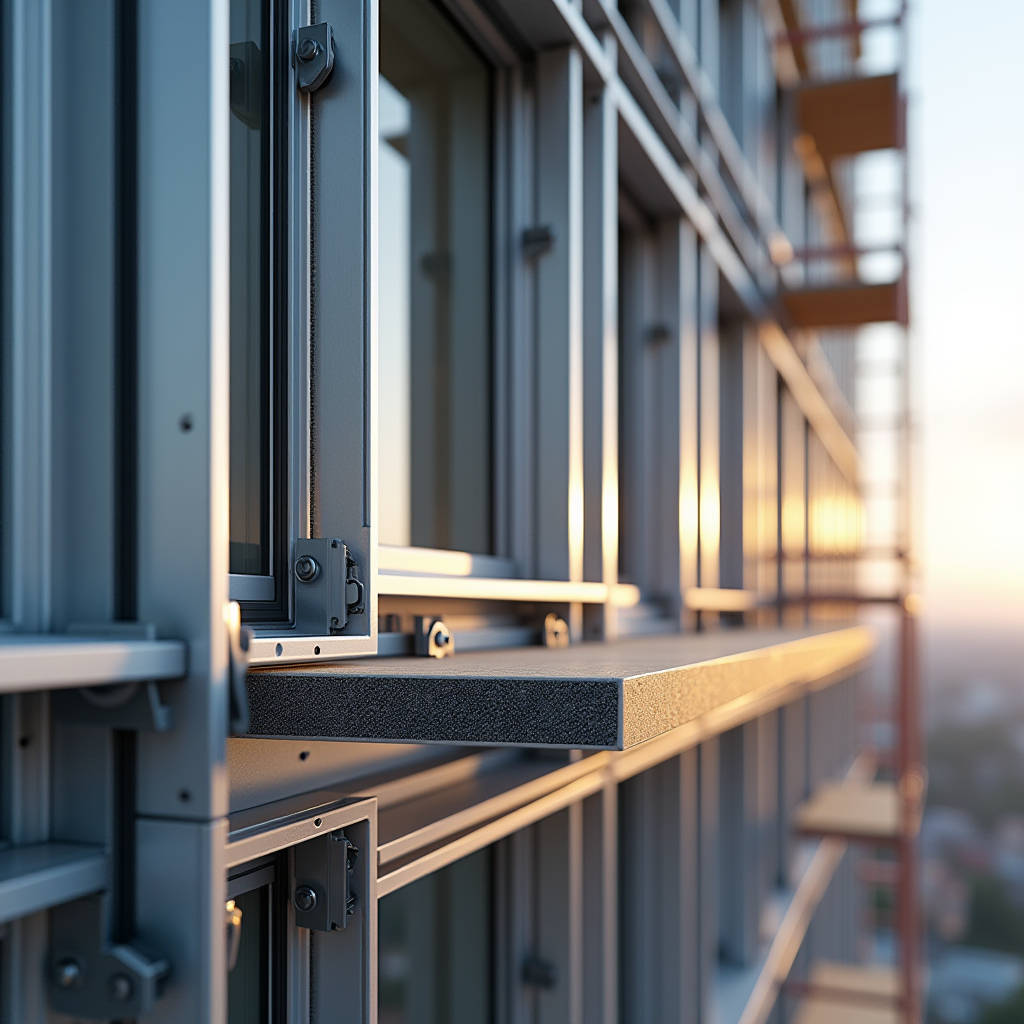
When architects and facade engineers specify curtain wall assemblies, the conversation inevitably turns to the substructure that holds everything together. An Aluminum Frame System is the hidden skeleton behind every successful cladding installation—the engineered grid of vertical mullions and horizontal transoms that transfers wind loads, accommodates thermal movement, and provides the precise plane onto which solid aluminium panels are mounted. Getting this substructure right determines whether a building envelope performs for 30 years or develops leaks, rattles, and visible deflection within the first five. This article examines the load-path engineering, material compatibility, and installation sequencing that separate a properly specified Aluminum Frame System from one that creates liability for everyone on the project team.
Why the Substructure Dictates Facade Performance
Solid aluminium cladding panels—typically 2.0mm, 2.5mm, or 3.0mm thick sheets with PVDF or powder-coated finishes—are only as flat and stable as the frame behind them. The panels themselves have inherent stiffness, but they rely on the Aluminum Frame System to handle the real structural work: dead load transfer, wind suction resistance, seismic drift accommodation, and thermal expansion management. A panel that looks perfect in the fabricator's shop can oil-can, deflect, or even detach if the supporting frame was designed around generic assumptions rather than project-specific calculations.
The core function of the frame is load distribution. When wind hits a building facade, the pressure doesn't distribute evenly across the surface. Corner zones experience suction forces 2.5 to 3 times higher than the center of the wall, per ASCE 7-22 provisions. The Aluminum Frame System must be engineered with varying member sizes and connection details across these zones. A mullion that works at mid-span with 30 psf design pressure may need to be upsized or reinforced at building corners where pressures reach 75 psf or higher. Skipping this zone-based analysis is one of the most common—and most expensive—errors in facade engineering.
Load Path Engineering: From Panel Face to Building Structure
Every component in the assembly must be sized for the loads it actually carries, and the connections between components must transfer those loads without deformation or loosening over time. The load path starts at the solid aluminium panel face, travels through the panel stiffeners and attachment clips, enters the horizontal transoms, transfers to the vertical mullions, and finally reaches the building's primary structure through adjustable brackets or embed channels.
At each interface, the Aluminum Frame System components must be checked for three failure modes: bending, shear, and connection pull-out. A mullion that is adequately sized for bending might still fail at the bracket connection if the fastener embedment depth or edge distance is insufficient. This is particularly critical when anchoring into concrete substrates, where ACI 318-19 provisions for anchor spacing and edge distances apply. Post-installed anchors in cracked concrete require additional reduction factors that can significantly reduce allowable loads.
Thermal Movement: The Silent Stressor
Aluminium expands at roughly 0.0000129 mm per mm per degree Celsius. On a 4-meter mullion length subjected to a 60°C temperature swing (from -10°C in winter to 50°C surface temperature in summer sun), the thermal expansion reaches approximately 3.1 mm. If the Aluminum Frame System does not accommodate this movement through slotted connections, expansion joints, or sliding brackets, the resulting stress manifests as panel buckling, fastener fatigue, or sealant joint failure. The fix isn't to eliminate movement—that's physically impossible—but to design the frame so movement happens at controlled locations without damaging the weather barrier.
Engineers typically specify thermal breaks at mullion splices every 3 to 4 meters and use slotted holes at bracket connections to allow longitudinal movement. The slot length is calculated based on the expected temperature range and the distance between fixed points. Getting this wrong means the frame fights itself, and the cladding panels are the first casualties.
Material Compatibility and Galvanic Corrosion Risk
Putting aluminium in contact with dissimilar metals in the presence of an electrolyte—rainwater, condensation, even high humidity—creates a galvanic cell. The aluminium becomes the anode and corrodes sacrificially. This is a well-documented failure mode in facade systems where stainless steel fasteners, carbon steel brackets, or copper flashings come into direct contact with the Aluminum Frame System without proper isolation.
The standard mitigation strategy follows the galvanic series: use fasteners and components that are cathodic to aluminium (such as 304 or 316 stainless steel) and provide physical separation where needed. Nylon washers, EPDM isolation pads, and coated fasteners are common solutions. The choice between 304 and 316 stainless depends on the environment. For coastal projects within 5 km of saltwater, 316 stainless is mandatory due to chloride-induced pitting resistance. For inland projects, 304 is generally adequate, though industrial environments with sulfur compounds may also warrant 316.
Futeng® has supplied solid aluminium cladding panels for projects where the specification explicitly required 316 stainless attachment hardware and EPDM isolation at every panel-to-frame connection point—a detail that added roughly 3-5% to the hardware cost but eliminated a corrosion risk that would have been far more expensive to remediate later.
Frame System Configurations: Stick-Built vs. Unitized
The two dominant approaches to Aluminum Frame System installation are stick-built and unitized, and the choice between them affects everything from shop drawing complexity to site logistics to long-term performance.
Stick-built systems involve delivering individual mullions, transoms, brackets, and panels to the site, then assembling the frame piece by piece on the building exterior. This approach offers maximum flexibility for complex geometries and field adjustments, but it requires skilled labor, extensive scaffolding or swing-stage access, and quality control that is entirely dependent on site conditions. A stick-built frame assembled in rain, extreme heat, or high winds will never achieve the same dimensional accuracy as one assembled in a controlled factory environment.
Unitized systems pre-assemble the Aluminum Frame System and cladding panels into large modules—typically one floor height by one or two bays wide—in a factory, then ship them to site for craning into position. The quality advantage is significant: factory tolerances of ±1.5 mm are achievable, versus ±3-5 mm for site-assembled stick systems. The trade-off is higher upfront engineering and logistics cost, and less flexibility for last-minute dimensional adjustments. Unitized systems also require careful sequencing of crane lifts and just-in-time delivery to avoid site storage issues.
| Parameter | Stick-Built System | Unitized System |
|---|---|---|
| Typical tolerance achievable | ±3.0 to ±5.0 mm | ±1.0 to ±1.5 mm |
| Site labor requirement | High (skilled glaziers/façade crews) | Moderate (crane and rigging crews) |
| Weather dependency | Significant (rain, wind, temperature) | Minimal (quick connection on site) |
| Engineering complexity | Moderate | High (transport and lifting loads) |
| Cost per m² (indicative, 2024) | $180 – $320 (frame + panel + labor) | $250 – $450 (frame + panel + labor) |
| Best suited for | Low/mid-rise, complex geometry, smaller footprints | High-rise, repetitive facades, tight urban sites |
| Thermal performance potential | Good (with site-installed insulation) | Excellent (factory-integrated insulation) |
| Remediation difficulty | Moderate (individual components accessible) | High (entire module may need replacement) |
Attachment Methods for Solid Aluminium Panels
How the solid aluminium panel connects to the Aluminum Frame System determines whether the facade reads as a perfectly flat plane or a wavy surface with visible fastener patterns. The industry recognizes four primary attachment methods, each with distinct aesthetic and performance implications.
Exposed Fastener Systems
The most economical approach uses stainless steel screws or rivets driven through the face of the panel into the frame. Fastener heads remain visible, typically with a painted or anodized cap to match the panel finish. This method is common in industrial and utilitarian applications where cost is the primary driver. The downside: fastener patterns create visual interruption, and each penetration is a potential leak path that requires gasketed washers and periodic inspection.
Concealed Clip and Rail Systems
Proprietary clip systems attach to the back of the panel and hook onto rails mounted on the Aluminum Frame System. The panel face remains completely clean with no visible fasteners. This is the dominant method for architectural cladding where appearance matters. The engineering challenge is ensuring the clips provide adequate pull-out resistance under wind suction while still allowing thermal expansion. Most systems use a combination of fixed points (to establish position) and sliding points (to accommodate movement).
Cassette and Tray Panel Systems
Solid aluminium panels are brake-formed into trays with returned edges, creating a cassette that hooks or clips onto the frame. The returned edges provide additional panel stiffness and create shadow lines that can mask minor dimensional variations. Cassette systems typically use 2.5mm or 3.0mm material to ensure the formed edges don't crack, and the bend radius must be at least equal to the material thickness to avoid stress concentration.
Structurally Bonded Systems
In this approach, the panel is bonded to a subframe using structural adhesive, and the subframe attaches to the main Aluminum Frame System. This eliminates all face penetrations and can produce exceptionally flat results. However, the adhesive must be tested for the specific temperature range, UV exposure, and dynamic loading conditions of the project. ASTM C1184 and the AAMA 810.1 guidelines provide testing protocols for structural silicone bonding in facade applications.
Deflection Limits: The Difference Between Flat and Wavy
Industry standards set maximum allowable deflections for frame members under design loads. The most commonly referenced limits come from AAMA TIR-A11 and the International Building Code (IBC). For aluminium curtain wall mullions, the typical limit is L/175 (span length divided by 175) for members supporting glass or brittle finishes. For members supporting metal panels, some engineers apply L/120, but this can produce visible waviness under certain lighting conditions.
The more conservative approach—and the one recommended for high-visibility facades with dark or glossy PVDF finishes—is to limit deflection to L/240 or even L/360. Dark finishes and high-gloss surfaces amplify the visual impact of any deviation from flatness. A 15 mm deflection that is invisible on a matte light-grey panel becomes objectionable on a gloss black panel. The Aluminum Frame System must be stiffened accordingly, which typically means reducing mullion spacing, increasing member depth, or adding intermediate transoms.
For reference, a 4.2-meter mullion span at L/175 allows 24 mm of deflection. At L/360, the same span allows only 11.7 mm. Achieving the tighter limit requires roughly 40% more section modulus, which translates to larger, heavier, and more expensive extrusions. The project team must decide early whether the aesthetic requirements justify the structural upgrade.
Wind Load Calculations and Zone Factors
Wind loading is the dominant design load for most Aluminum Frame System applications. The calculation methodology in ASCE 7-22 accounts for building height, exposure category, topographic effects, and the building's shape. The result is a design pressure map that varies across the facade surface, with corner and edge zones requiring higher capacity than interior zones.
For a typical 60-meter-tall building in Exposure Category B (suburban/urban terrain), the design wind pressure at the building corner might be 2.8 kPa (58 psf), while the interior zone might be 1.2 kPa (25 psf). The frame members in the corner zone must be designed for the higher pressure, which often means closer spacing, heavier sections, or both. Some projects use a uniform frame design based on the worst-case zone, which simplifies fabrication but adds cost and weight to areas that don't need it. The more efficient approach zones the frame design, which requires more complex shop drawings but optimizes material usage.
Wind tunnel testing, while more expensive than analytical methods, can often justify reduced design pressures compared to code-prescribed values, particularly for buildings with unusual shapes or in complex urban environments. The cost of a wind tunnel study—typically $30,000 to $80,000—can be recovered many times over through frame material savings on a large facade.
Seismic Considerations for Frame Design
In seismic regions, the Aluminum Frame System must accommodate inter-story drift without losing support for the cladding panels or damaging the weather barrier. The IBC requires facade systems to accommodate the design story drift, which for a typical steel-framed building might be 2.0% to 2.5% of the story height. For a 4-meter story height, that's 80 to 100 mm of horizontal movement.
The frame achieves this through slotted connections that allow the panel to slide relative to the structure, and through joint designs that can open and close without tearing the sealant. The sealant joints at panel perimeters are typically designed for ±50% movement capability, meaning a 20 mm joint can accommodate 10 mm of compression and 10 mm of extension. Silicone sealants meeting ASTM C920 Class 50 provide this capability, while lower-performance sealants may fail at lower movement ranges.
Seismic qualification testing per AAMA 501.4 and AAMA 501.6 provides documented evidence that the specific Aluminum Frame System and panel combination can survive the design drift without structural failure or water penetration. Testing is performed on a full-scale mockup that includes the frame, panels, anchors, and sealant joints, subjected to the calculated drift cycles.
Corrosion Protection and Finish Durability
The aluminium extrusions that form the Aluminum Frame System are typically supplied with either an anodized finish (per AAMA 611) or a painted finish (per AAMA 2604 or 2605). The choice depends on the environment and the visibility of the frame.
Anodizing creates a hard, transparent aluminum oxide layer that is integral to the metal surface. Class I anodizing (minimum 18 microns thickness) is specified for exterior applications. It provides excellent corrosion resistance but limited color options—typically clear, champagne, or dark bronze. The anodized layer is electrically non-conductive, which can affect grounding requirements for lightning protection systems.
For frames that will be visible, AAMA 2604 (high-performance organic coating) or AAMA 2605 (superior-performance organic coating) finishes provide a wider color range and better gloss retention. AAMA 2605, which is the same specification used for PVDF coatings on solid aluminium cladding panels, provides 10-year South Florida exposure performance with minimal color change and chalking. When the frame is hidden behind panels, a mill finish or Class I anodized finish is typically adequate.
For the solid aluminium panels themselves, PVDF coatings meeting AAMA 2605 with a minimum 70% resin content (typically Kynar 500® or Hylar 5000®) and a total dry film thickness of 30-35 microns remain the industry standard for architectural applications. The coating system includes a primer layer for corrosion protection and adhesion, a color coat, and a clear topcoat for UV resistance.
Quality Control During Frame Installation
Even the best-engineered Aluminum Frame System fails if installed without proper alignment and quality control. The critical checks during installation include:
- Anchor embedment and torque: Every anchor must be set to the manufacturer's specified torque, and a sample (typically 10% or minimum 5 per floor) should be torque-tested and documented. Undertorqued anchors allow movement; overtorqued anchors can fracture the concrete or strip threads.
- Mullion alignment: Vertical mullions must be checked for plumb within ±3 mm over the full height. Out-of-plumb mullions create cumulative alignment errors that become visible at panel joints.
- Transom level: Horizontal transoms must be level within ±2 mm over any 3-meter length. Out-of-level transoms cause panel stepping and uneven joint widths.
- Joint width consistency: Panel-to-panel joints should be checked with a go/no-go gauge at regular intervals. Joint width variation of more than ±2 mm from the specified dimension is visually noticeable.
- Sealant joint preparation: Joints must be clean, dry, and primed if required by the sealant manufacturer. Backer rod must be installed at the correct depth to achieve the proper sealant hourglass profile.
Documentation of these checks, typically through a quality assurance log signed by the installer and verified by the facade consultant, provides the paper trail that protects all parties if performance issues arise later.
Supply Chain and Lead Time Realities
Aluminium extrusion lead times for custom frame profiles typically run 8 to 14 weeks from approved shop drawings, depending on die fabrication requirements and mill scheduling. Standard T-slot profiles and catalog extrusions can ship in 4 to 6 weeks. Solid aluminium cladding panels add another 6 to 10 weeks for fabrication, including shearing, forming, welding of stiffeners, and finishing.
The total lead time from order to delivery for a complete Aluminum Frame System with solid aluminium panels is typically 16 to 24 weeks. Projects that require custom extrusion dies, complex panel geometries, or specialty finishes should budget toward the upper end of that range. Rush orders are possible but typically incur 15-25% surcharges and may still be constrained by mill capacity.
For international procurement, shipping adds 4 to 8 weeks depending on origin and destination, plus customs clearance time. Some project teams manage this by air-freighting a small quantity of critical components to meet early installation milestones while the bulk ships by sea.
ASTM International provides the governing standards for aluminium extrusion tolerances under ASTM B221, while the Aluminum Association publishes the Aluminum Design Manual with allowable stress design values for structural aluminium members. The American Architectural Manufacturers Association maintains AAMA 611, 2604, and 2605 finish specifications referenced throughout facade engineering.
Practical Recommendations for Specification Writers
Based on the engineering principles outlined above, a specification for an Aluminum Frame System supporting solid aluminium cladding panels should address the following points with project-specific values rather than generic language:
- Define the design wind pressures by zone (corner, edge, interior) with the specific ASCE 7-22 parameters used in the calculation.
- Specify the maximum allowable deflection limit—L/240 or L/360 for high-visibility facades, not the more permissive L/120 sometimes used for metal panels.
- Require thermal movement calculations demonstrating that the frame design accommodates the expected temperature range without imposing stress on the panels.
- Mandate isolation between dissimilar metals, with specific materials (EPDM, nylon, or coated fasteners) called out.
- Include seismic drift accommodation requirements with reference to the structural engineer's calculated story drift values.
- Require a full-scale mockup test per AAMA 501 series for projects over 4 stories or with complex geometries.
- Specify finish standards: AAMA 2605 for visible frame components and panel faces, AAMA 611 Class I for concealed frame members.
The engineering behind a properly specified Aluminum Frame System is not esoteric—it is applied mechanics, material science, and construction logistics combined. The difference between a facade that performs and one that generates callbacks is rarely the quality of the aluminium itself. It is the attention paid to load paths, thermal movement, corrosion isolation, and installation tolerances. When these elements are specified correctly and verified in the field, solid aluminium cladding on a well-engineered frame delivers decades of low-maintenance performance. When they are overlooked, the problems appear long before the warranty expires.