Aluminum Facade Profile Engineering From Alloy Selection to Wind Load Performance
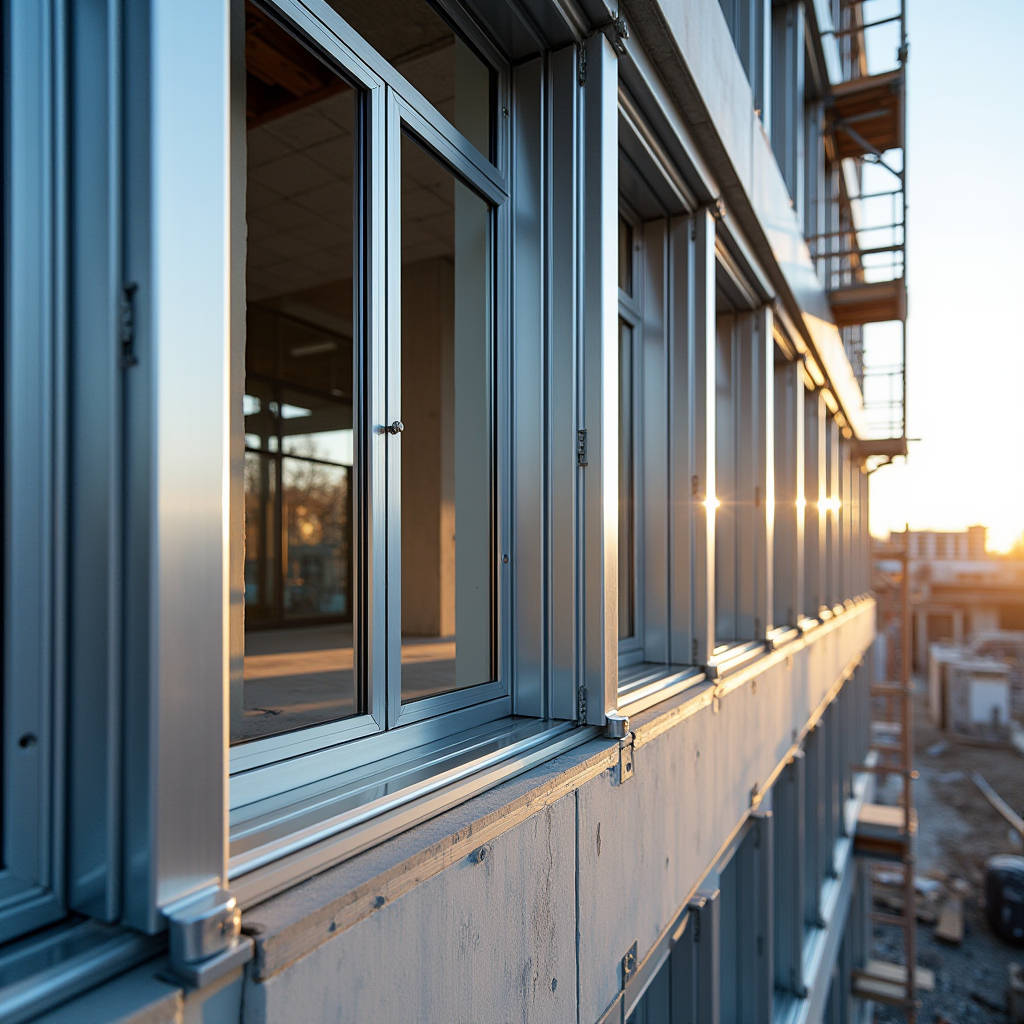
When a facade contractor asks about Aluminum Facade Profile specifications, the conversation rarely stays surface-level for long. The profile — the extruded aluminum section that frames, supports, and defines the outer skin of a building — sits at the intersection of structural engineering, thermal physics, and architectural intent. Get it wrong, and you inherit water ingress, galvanic corrosion, or a thermal bridge that undermines the entire envelope performance. Get it right, and the same profile disappears into the background, quietly doing its job for 40 years. This article drills into the specific engineering decisions that determine whether an Aluminum Facade Profile performs or fails: alloy selection, thermal break geometry, wind load deflection limits, and the often-overlooked interface between extruded profiles and solid aluminium cladding panels in rainscreen assemblies.
What an Aluminum Facade Profile Actually Does Structurally
An Aluminum Facade Profile in a rainscreen or curtain wall system performs three distinct mechanical functions. First, it transfers dead load — the weight of the cladding panels, typically solid aluminium sheets at 2.0 to 3.0mm thickness — back to the primary structure through a series of brackets and anchors. Second, it resists wind load, both positive pressure pushing the cladding inward and negative suction trying to peel it off the building. Third, it accommodates thermal movement. Aluminum expands at roughly 2.4mm per meter per 100°C temperature swing. A 4-meter profile on a south-facing elevation in Dubai experiences significantly different dimensional changes than the same profile on the north elevation. The profile system must absorb this movement without buckling, squeaking, or transferring stress into the panel fixings.
The load path is straightforward but unforgiving. Wind hits the solid aluminium panel, which transfers load to the profile carrier rails, which transfer to vertical mullions or horizontal transoms, which connect to structural brackets, which anchor into the slab edge or steel frame. Each connection point introduces a potential failure mode. Engineers who treat the Aluminum Facade Profile as a simple spacer rather than a load-bearing element eventually field calls about rattling panels and cracked sealant joints.
Alloy Selection: 6063-T6 vs 6061-T6 vs 6082-T6
Not all aluminum is equal, and the choice of extrusion alloy for an Aluminum Facade Profile has downstream consequences for fabrication, finishing, and long-term durability. The three alloys most commonly specified for architectural extrusions each occupy a distinct niche.
6063-T6 dominates architectural applications for good reason. It extrudes beautifully, achieving tight tolerances and complex hollow geometries that would tear or collapse in harder alloys. Its surface finish after anodizing is consistently excellent — fine-grained, uniform, and free of the streaking that plagues higher-copper alloys. The trade-off is strength. With a typical ultimate tensile strength around 215 MPa, 6063-T6 works for most mid-rise curtain wall applications but may require thicker wall sections for long spans or high wind zones.
6061-T6 offers roughly 40% higher tensile strength (310 MPa) than 6063-T6, making it attractive for structural mullions in high-rise or coastal projects. The downside: it extrudes more slowly, costs more per kilogram, and produces a less predictable anodized finish. Many specifiers reserve 6061-T6 for primary structural members and pair it with 6063-T6 for visible trim and cover caps.
6082-T6 sits between the two in strength (around 290 MPa) and offers excellent corrosion resistance — a critical factor in marine environments. European projects increasingly specify 6082-T6 for Aluminum Facade Profile systems where both structural performance and coastal durability matter. The alloy welds well and machines cleanly, though extrusion die wear is higher than with 6063.
| Alloy | Tensile Strength (MPa) | Yield Strength (MPa) | Elongation (%) | Anodizing Quality | Best Application |
|---|---|---|---|---|---|
| 6063-T6 | 215 | 170 | 8-10 | Excellent | Standard curtain wall, visible trim |
| 6061-T6 | 310 | 275 | 12 | Good (may streak) | High-load mullions, long spans |
| 6082-T6 | 290 | 250 | 10 | Very Good | Marine environments, structural frames |
Thermal Break Technology: Polyamide vs Polyurethane
The thermal performance of an Aluminum Facade Profile hinges on one component: the thermal break. Without it, an aluminum profile acts as a direct thermal bridge, conducting heat from the exterior to interior at roughly 160 W/m·K. With a properly designed thermal break, that conductivity drops dramatically, enabling U-values below 2.0 W/m²·K for the frame assembly.
Two technologies dominate the market. Polyamide (PA66) strips reinforced with glass fiber are the industry standard for premium systems. Reynobond, Schüco, and similar European systems use PA66 strips mechanically crimped into dedicated channels in the aluminum extrusion. The glass fiber reinforcement (typically 25%) controls thermal expansion of the strip so it expands and contracts at a rate close to aluminum, preventing delamination over decades of thermal cycling. The strip width — ranging from 18mm to 42mm — directly determines the thermal performance. Wider strips mean lower U-values but also reduce the profile's moment of inertia, requiring deeper aluminum sections to compensate.
Pour-and-debridge polyurethane offers a lower-cost alternative. The process pours liquid polyurethane into a cavity in the extrusion, cures it, then cuts away the aluminum bridge that originally connected the interior and exterior halves. The resulting thermal break is narrower than a PA66 strip but can achieve respectable performance. The risk is long-term creep under sustained load — polyurethane relaxes over time, potentially loosening the mechanical bond between the two aluminum halves. For high-rise applications where profile deflection must stay within L/175 or tighter, PA66 strips remain the safer choice.
A third option, polyester-reinforced nylon, appears in some North American systems. It offers intermediate cost and performance but lacks the track record of PA66 in extreme climates. When specifying, ask for the thermal break supplier's test data per AAMA 505-18 (Dry Shrinkage and Thermal Cycling) rather than relying on marketing claims.
Wind Load Deflection and the L/175 Standard
Wind load governs Aluminum Facade Profile design more than any other factor. The governing standard for deflection limits varies by region and system type. The most commonly referenced limit is L/175 — meaning the profile must not deflect more than its span divided by 175 under design wind load. For a 3.5-meter mullion span, that translates to a maximum deflection of 20mm. Some specifications tighten this to L/240 for brittle finishes like stone veneer, or relax it to L/125 for industrial buildings where aesthetics matter less.
The calculation itself follows ASTM E1300 or EN 1999-1-1, depending on jurisdiction. The key inputs are the profile's moment of inertia (I-value), the design wind pressure (converted from the project's basic wind speed per ASCE 7 or EN 1991-1-4), and the span between supports. A profile with an I-value of 250 cm⁴ might handle a 3-meter span at 1.5 kPa, but stretch the span to 4 meters and the required I-value jumps to over 500 cm⁴ — often requiring a deeper profile section or a switch from 6063-T6 to 6061-T6 alloy.
What gets overlooked: torsional deflection. When wind hits a corner zone of a building, the pressure distribution isn't uniform. The Aluminum Facade Profile experiences twisting as well as bending. Standard deflection calculations assume uniform loading. Engineers should request FEA (finite element analysis) verification for corner profiles, parapet conditions, and any profile spanning more than 4 meters. Suppliers like Futeng® provide FEA reports as part of their engineering package for complex facade geometries, which saves the contractor from having to commission independent structural analysis.
Interface Between Extruded Profiles and Solid Aluminium Cladding Panels
A rainscreen system is only as good as the connection between its two main components: the extruded Aluminum Facade Profile substructure and the solid aluminium cladding panels that form the visible outer skin. This interface involves multiple engineering decisions that cascade into cost, durability, and thermal performance.
Clip vs cassette fixation. Clip systems use discrete aluminum brackets — typically spaced at 300-600mm centers — that engage folded returns on the panel edges. The panel hangs on the clips, allowing free thermal expansion in all directions. Cassette systems fold the panel edges into a tray that slots into the profile grid, creating a more rigid connection but requiring careful detailing of expansion joints. Clip systems dominate ventilated rainscreens because they decouple panel movement from profile movement, reducing stress concentrations and eliminating visible fasteners.
Panel thickness and profile spacing. A 2.5mm solid aluminium panel with PVDF coating weighs approximately 6.8 kg/m². When supported on profiles at 600mm centers, the panel's bending stiffness is more than adequate for wind zones up to 2.5 kPa. Stretch the profile spacing to 900mm, and the panel may require 3.0mm thickness or intermediate stiffeners to avoid oil-canning — that visible waviness in the panel surface that becomes apparent under raking light. The relationship between panel thickness, profile spacing, and wind load follows a cubic function: doubling the spacing requires roughly eight times the panel stiffness to maintain the same deflection.
Galvanic corrosion risk. Aluminum profiles in contact with steel fasteners, stainless steel anchors, or copper flashings create a galvanic cell in the presence of moisture. The aluminum — being the more anodic metal — sacrifices itself. Prevention requires isolating dissimilar metals with nylon washers, EPDM gaskets, or proprietary isolation tapes. The AAMA 2604 and 2605 coating standards address the organic coating side of corrosion protection, but the mechanical isolation of metals is a detailing issue that falls squarely on the facade engineer.
Coating Systems for Extruded Profiles
While solid aluminium panels typically receive PVDF (polyvinylidene fluoride) coil coatings meeting AAMA 2605, extruded Aluminum Facade Profile sections follow a different finishing path. The three dominant options each carry distinct performance profiles.
Anodizing (AAMA 611-14 Class I) produces an aluminum oxide layer 18-25 microns thick that is integral to the metal surface — it cannot peel or flake. Class I anodizing delivers excellent UV resistance and works well in dry, non-industrial atmospheres. In coastal or industrial environments, Class II anodizing (10-15 microns) is inadequate. The limitation: anodizing shows die lines, weld marks, and alloy variations more readily than paint, and the color range is limited to champagne, bronze, and black tones.
PVDF liquid spray (AAMA 2605) applies a 30-40 micron fluoropolymer coating to the extruded profile, matching the panel finish exactly. This is the standard choice when the architect demands uniform color between panels and profiles. The 70% PVDF resin content ensures 20+ year color retention and chalk resistance. The process requires a chromate conversion coating pretreatment, which adds cost and environmental compliance requirements.
Powder coating (AAMA 2604) uses polyester or super-durable polyester powders electrostatically applied and oven-cured at 180-200°C. Super-durable polyester powders now rival PVDF for color stability in all but the most extreme UV environments, and they cost roughly 30-40% less than PVDF liquid spray. The film thickness is higher — 60-80 microns — providing better impact resistance, which matters for profiles at ground level subject to pedestrian traffic and maintenance equipment.
| Finish Type | Standard | Film Thickness | Color Retention | Cost Index | Best For |
|---|---|---|---|---|---|
| Class I Anodizing | AAMA 611 | 18-25 μm | 30+ years | 1.0 | Low-traffic, dry climates |
| PVDF Liquid Spray | AAMA 2605 | 30-40 μm | 20+ years | 1.8 | Color-matched panel/profile systems |
| Super-Durable Powder | AAMA 2604 | 60-80 μm | 15-20 years | 1.3 | High-traffic, budget-conscious |
| Standard Polyester Powder | AAMA 2603 | 50-70 μm | 5-10 years | 1.0 | Interior or sheltered applications |
Profile Geometry and the Moment of Inertia
The shape of an Aluminum Facade Profile determines its structural efficiency. A solid rectangular bar of aluminum is heavy, expensive, and structurally inefficient. Hollow profiles with internal webs put material where it contributes most to bending stiffness — at the extreme fibers of the section. The moment of inertia (I) quantifies this efficiency. For a given cross-sectional area, a hollow rectangular profile 100mm deep with 3mm wall thickness delivers roughly 8 times the bending stiffness of a solid 50mm x 10mm flat bar.
The profile designer's challenge is balancing I-value against weight, cost, and thermal performance. Deepening the profile section increases I linearly with the cube of depth — doubling the depth increases stiffness eightfold. But deeper profiles require wider thermal breaks, which cost more and reduce the profile's effective structural depth. Adding internal screw ports for bracket attachment creates local stress concentrations that must be accounted for in FEA. Every internal web, groove, and gasket channel adds die complexity and extrusion cost.
For projects specifying solid aluminium cladding panels at 2.5mm or 3.0mm thickness, the profile system typically requires a minimum I-value of 150-200 cm⁴ for vertical mullions at 1200mm spacing and 3.5m spans under 1.5 kPa wind load. This can be achieved with a 6063-T6 profile approximately 120mm deep by 60mm wide, with 2.5-3.0mm wall thickness. Lighter profiles may pass deflection checks but fail under the combined loading of panel weight, wind suction, and thermal cycling.
Fire Performance and EN 13501-1 Classification
Aluminum melts at approximately 660°C. In a fully developed building fire, temperatures can exceed 800°C within minutes. This means an Aluminum Facade Profile will lose structural integrity during a fire — the question is how quickly, and whether the system design provides adequate fire containment.
Under EN 13501-1, aluminum itself achieves classification A1 (non-combustible). But the complete facade assembly — including thermal breaks, gaskets, insulation, and the cladding panels — must be tested as a system. The thermal break is the weak point. PA66 strips soften and lose strength above 250°C, well before the aluminum melts. Some systems incorporate stainless steel reinforcement pins through the thermal break zone to maintain structural integrity during the early stages of a fire, buying time for evacuation.
The UK's post-Grenfell regulatory environment has sharpened focus on facade fire performance globally. BS 8414 large-scale facade fire testing is now referenced in projects far beyond the UK. Specifiers should request full system test reports rather than relying on individual component classifications. A profile with A1-rated aluminum and A2-rated insulation can still fail a system test if the thermal break, gaskets, or panel fixings create a fire propagation path.
Supply Chain Realities: Lead Times, Die Costs, and MOQs
Custom Aluminum Facade Profile extrusion involves upfront tooling investment that catches many project budgets off guard. A new extrusion die for a moderately complex hollow profile costs between $3,000 and $8,000, depending on profile diameter and complexity. Simple open profiles (angles, channels, flat bars) can be as low as $1,500. The die typically lasts for 20-30 tonnes of extrusion before requiring refurbishment or replacement — sufficient for most medium to large facade projects.
Minimum order quantities (MOQs) vary by extruder and region. European extruders often require 500-1,000 kg per profile shape. Chinese and Turkish extruders — including established suppliers like Futeng® — typically accept 300-500 kg MOQs, making custom profiles viable for smaller projects. Lead times for new dies run 4-6 weeks, plus 2-3 weeks for extrusion and 2-3 weeks for finishing (anodizing or coating). The total lead time from drawing approval to delivery is typically 10-14 weeks, which must be factored into the construction schedule.
Standard profiles — those available from system suppliers' catalogs — ship in 2-4 weeks but limit design flexibility. The decision between standard and custom profiles should be made during the design development phase, not during procurement, to avoid schedule compression.
Installation Tolerances and Field Adjustments
The theoretical precision of extruded Aluminum Facade Profile sections — typically ±0.5mm on critical dimensions — collides with the reality of cast-in-place concrete slabs that can deviate ±25mm from design position. The bracket system must absorb this discrepancy. Three-dimensional adjustable brackets, offering ±30mm of adjustment in the horizontal plane and ±20mm vertically, have become standard for rainscreen systems. The bracket connects to the slab edge via stainless steel anchors, with serrated mating surfaces that lock under bolt tension to prevent long-term creep.
Field cutting of profiles is inevitable but should be minimized. Every field-cut end requires deburring and, ideally, touch-up coating to prevent corrosion initiation at the cut edge. Profiles that arrive pre-cut to length from the factory, with pre-punched drainage slots and bracket attachment holes, reduce site labor and improve quality. The cost premium for factory fabrication — typically 15-25% over bulk lengths — is usually recovered through reduced installation time and fewer callbacks.
Thermal expansion joints in the profile grid must be detailed at the shop drawing stage, not improvised on site. A 30-meter continuous run of Aluminum Facade Profile will expand approximately 18mm across a 50°C temperature swing. Without properly detailed expansion joints at 10-15 meter intervals, the profiles will buckle or shear their fixings. The expansion joint detail typically involves a sliding sleeve inside one profile that telescopes into the adjacent profile, maintaining weather tightness while allowing movement.
Specifying for Coastal and Industrial Environments
Salt spray, sulfur dioxide, and acid rain attack aluminum through different mechanisms, and the Aluminum Facade Profile specification must account for the specific environmental exposure. ISO 9223 classifies atmospheric corrosivity from C1 (very low, indoor) to CX (extreme, offshore). Most urban environments fall into C3 (medium). Coastal zones within 5km of breaking surf are C4 (high) or C5 (very high).
For C4 and C5 environments, 6082-T6 alloy with Class I anodizing to 25 microns or PVDF coating per AAMA 2605 provides adequate protection. The critical detail is drainage: profiles must include weep holes at every horizontal junction to prevent water accumulation. Standing water in profile cavities concentrates contaminants and accelerates pitting corrosion. All stainless steel fasteners should be grade 316 (A4) rather than 304 (A2) for coastal applications. The incremental cost of 316 fasteners is negligible compared to the cost of replacing corroded fixings on a completed facade.
Industry data from the American Architectural Manufacturers Association (AAMA) indicates that properly specified and maintained aluminum facade systems in C4 environments routinely achieve 40-year service lives without significant structural degradation.
Making the Engineering Case
The Aluminum Facade Profile is not a commodity item to be value-engineered down to the lowest bid. It is a load-bearing, weather-resisting, thermally-critical component that determines whether the building envelope performs as designed or becomes a source of chronic problems. The alloy choice, thermal break design, coating system, and installation detailing all interact in ways that a simple price-per-kilogram comparison cannot capture.
For contractors and specifiers evaluating profile systems, the priority list should be: first, verify structural adequacy through FEA or span tables matched to the project's wind loads; second, confirm thermal performance through hot-box testing or validated thermal models; third, audit the coating durability through independent test reports per AAMA 2605 or equivalent; fourth, review the bracket system's adjustment range against the expected slab tolerances. Only after these engineering checks should unit pricing enter the conversation.
The solid aluminium cladding panels that hang on these profiles — whether 2.0mm, 2.5mm, or 3.0mm thick, PVDF-coated or anodized — depend entirely on the profile system for their long-term stability. A panel is only as secure as the profile that holds it. That reality, more than any aesthetic consideration, should drive the specification process.