Aluminum Extrusion Profile Engineering for Solid Aluminium Cladding Sub Frames
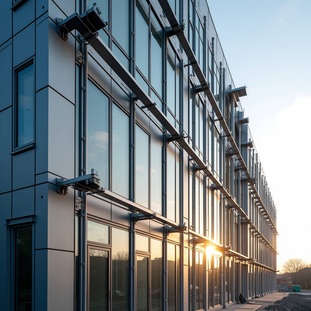
When a curtain wall consultant specifies an Aluminum Extrusion Profile as a structural framing member behind solid aluminium cladding, the conversation shifts from simple panel selection to a complex interplay of thermal movement, galvanic corrosion risk, and load distribution. An Aluminum Extrusion Profile is not merely a shape pulled through a die. In the context of a rainscreen or unitized curtain wall system, it functions as the sub-frame that transfers wind loads, accommodates thermal expansion of the outer skin, and defines the cavity depth for ventilation. Getting this interface wrong means panels that oil-can under thermal stress, fasteners that corrode within five years in a coastal environment, or a sub-frame that deflects beyond L/360 under negative wind pressure. This article examines the engineering decisions that govern how extruded aluminum sub-frames perform behind 2.0mm to 3.0mm solid aluminium cladding panels, with a focus on alloy selection, thermal break integration, and the tolerance stack that determines whether a facade reads as perfectly planar or visibly wavy from street level.
The Engineering Role of Extruded Sub-Frames in Solid Cladding Systems
Behind every square meter of solid aluminium cladding sits a grid of extruded aluminum members that rarely gets the same attention as the visible panel face. This grid carries dead load, transfers wind suction and pressure to the primary structure, and creates the air gap that makes a rainscreen function as a rainscreen. The Aluminum Extrusion Profile used here differs fundamentally from the T-slot framing found in machine guarding or workstations. Architectural sub-frame profiles are typically open-channel or hat-shaped sections with integrated screw ports, gasket races, and thermal break cavities designed into the die.
The profile geometry determines three things simultaneously: the moment of inertia that resists bending, the thermal path length that governs heat transfer, and the attachment interface that dictates how panels are fixed. A hat section 80mm deep with 2.5mm wall thickness might deliver a moment of inertia around 45 cm⁴, sufficient for a 1.5m span at 1.8 kPa design wind pressure. But that same section, if not designed with a proper thermal break, creates a linear thermal bridge with a U-value penalty that can push a wall assembly out of compliance with ASHRAE 90.1. Engineers at Futeng® have observed that specifying the sub-frame profile without coordinating the thermal break geometry with the panel joint pattern is one of the most common root causes of on-site rework in unitized systems.
Alloy Selection: 6063-T6 vs. 6061-T6 vs. 6082-T6
The choice of extrusion alloy is not a default decision. Each alloy brings a different balance of extrudability, corrosion resistance, and mechanical strength that directly affects how the sub-frame performs behind solid aluminium cladding.
| Alloy | Yield Strength (MPa) | Tensile Strength (MPa) | Elongation (%) | Corrosion Resistance | Typical Architectural Use |
|---|---|---|---|---|---|
| 6063-T6 | 170 | 215 | 8-10 | Excellent | Standard sub-frame, mullions, pressure plates |
| 6061-T6 | 240 | 290 | 10 | Very Good | High-load brackets, anchor channels |
| 6082-T6 | 260 | 310 | 8 | Very Good | Heavy-duty structural connections |
| 6060-T6 | 150 | 190 | 10-12 | Excellent | Complex thin-wall profiles, tight radii |
6063-T6 dominates architectural extrusion because it flows through complex dies with excellent surface finish and takes anodizing uniformly. For a typical Aluminum Extrusion Profile used as a vertical mullion behind solid aluminium panels, 6063-T6 provides adequate strength while keeping extrusion costs manageable. However, when the sub-frame must cantilever beyond 300mm or carry concentrated loads at anchor points, 6061-T6 or 6082-T6 becomes necessary. The trade-off is that 6061 extrudes roughly 30% slower than 6063 and wears dies faster, adding 15-20% to the per-meter cost of the profile. The decision should be driven by a structural calculation, not a generic specification copied from a previous project.
Thermal Movement: The Hidden Load Case
Solid aluminium cladding panels and their extruded sub-frames both expand and contract with temperature, but they do so at different rates and on different schedules. A dark-colored PVDF-coated panel facing direct sun can reach 80°C while the sub-frame behind the insulation stays at 35°C. The differential expansion between a 3.0mm solid aluminium panel (coefficient of thermal expansion: 23.6 × 10⁻⁶ /°C) and the Aluminum Extrusion Profile supporting it creates shear forces at the fastener points.
Consider a 3-meter panel length with a 45°C temperature differential between panel and sub-frame. The unrestrained expansion difference is approximately 3.2mm. If the panel is rigidly fixed at both ends, this generates compressive stress that manifests as oil-canning: the visible rippling of the panel surface that is optically unacceptable on a flat facade. The engineering solution involves three coordinated strategies. First, specify slotted connections at one end of each panel to allow longitudinal slip. Second, design the extrusion's screw port geometry to accept a nylon or stainless steel bushing that isolates the fastener from the panel. Third, maintain a minimum 10mm cavity depth behind the panel to prevent the expanded panel from contacting the insulation layer.
The American Architectural Manufacturers Association (AAMA) provides guidance on thermal movement accommodation in AAMA TIR-A14, which should be referenced in any specification that involves dark-colored solid aluminium cladding in high solar exposure climates.
Galvanic Corrosion Risk at the Extrusion-to-Panel Interface
When an Aluminum Extrusion Profile contacts a stainless steel fastener that penetrates a solid aluminium panel, the galvanic potential difference between the materials determines whether corrosion will initiate. Aluminium and stainless steel are relatively close on the galvanic series in dry conditions, but in the presence of an electrolyte—rainwater, coastal salt spray, or condensation within the cavity—the potential difference can drive corrosion of the anodic aluminium.
The risk is highest in marine and industrial environments. A 316 stainless steel self-tapping screw driven directly into an extruded aluminum sub-frame without isolation creates a galvanic cell where the aluminum sacrificially corrodes. Over 5-7 years in a coastal setting, this can enlarge the screw hole to the point where the panel loses structural engagement. The fix is straightforward but frequently omitted: specify a nylon or EPDM isolation washer at every fastener penetration, and ensure the fastener itself has a coating compatible with aluminium contact. The ISO 9223:2012 standard classifies atmospheric corrosivity categories and should inform the material selection for any project within 5km of a coastline or in an industrial zone with SO₂ emissions.
Profile Geometry and Wind Load Performance
The cross-sectional geometry of an Aluminum Extrusion Profile determines its section properties: moment of inertia (Iₓ, Iᵧ), section modulus (Sₓ, Sᵧ), and radius of gyration. These values feed directly into deflection checks under wind load. For solid aluminium cladding sub-frames, the governing deflection limit is typically L/360 for spans under 3 meters, tightened to L/480 for spans exceeding 4 meters or where brittle finishes are applied to the panel face.
A common error is to select a profile based on its depth alone. A 100mm deep hat section with 2.0mm wall thickness might have a lower moment of inertia than an 80mm deep section with 3.0mm walls and optimized rib placement. The Aluminum Extrusion Profile die design should concentrate material at the flanges—the top and bottom of the section—where it contributes most to bending resistance. Hollow profiles with internal webs can achieve 30-40% higher stiffness than open sections of equivalent weight, but they cost more to extrude and complicate drainage.
For a typical mid-rise office building with a design wind pressure of 2.4 kPa (corresponding to roughly 180 km/h basic wind speed at 30m height in Exposure Category B per ASCE 7), a 6063-T6 vertical mullion with Iₓ = 55 cm⁴ spanning 3.2m between floor anchors will deflect approximately 6.5mm under service load. This is within L/360 (8.9mm) but the specifier should verify that the panel joint width can accommodate this deflection without the panels contacting each other.
Thermal Break Integration in Extruded Profiles
Building codes increasingly demand continuous insulation and thermal break continuity in the building envelope. An Aluminum Extrusion Profile that bridges from the warm interior to the cold exterior without a thermal break creates a linear thermal transmittance (Psi-value) that can degrade the overall wall U-value by 15-25% depending on mullion spacing.
Thermal break technology for aluminum extrusions falls into two categories. The first is the pour-and-debridge method, where a polyurethane resin is poured into a channel in the extrusion, allowed to cure, and then the aluminum bridge is machined away to create a structural thermal separation. This method achieves a thermal conductivity of approximately 0.12 W/m·K through the break and is standardized under AAMA 505. The second method uses polyamide strips (PA66 with 25% glass fiber) that are mechanically crimped into the extrusion. These strips offer higher shear strength—important for carrying panel dead load across the thermal break—and a thermal conductivity around 0.30 W/m·K.
The specifier must confirm that the thermal break design accounts for the eccentric loading condition where the solid aluminium panel hangs on the exterior side of the break, creating a rotational moment that the polyamide strips must resist. This is not a theoretical concern: failed thermal breaks have been documented in projects where the strip depth was insufficient for the panel weight and wind suction combination.
Tolerance Stack: From Extrusion Die to Finished Facade
The flatness of a solid aluminium cladding facade depends on a chain of tolerances that starts at the extrusion die and ends at the panel fastener. An Aluminum Extrusion Profile leaves the die with dimensional tolerances governed by The Aluminum Association standard tolerance tables. For a profile with a circumscribing circle diameter of 150mm, the standard tolerance on a critical dimension is ±0.38mm for the first 75mm, plus ±0.025mm for each additional 25mm. Twist tolerance is typically 0.5° per 300mm of length.
These raw extrusion tolerances compound with the fabrication tolerances of the sub-frame assembly: cut length accuracy (±0.5mm is achievable with CNC sawing), hole position accuracy for screw ports (±0.3mm), and the straightness of the assembled grid on the building structure. When the sub-frame grid accumulates a position error of 2-3mm over a 6-meter bay, the solid aluminium panels—which are themselves fabricated to a flatness tolerance of 0.5mm per 300mm—cannot absorb that error without visible stepping at the joints.
The solution is to design adjustment capacity into the connection between the Aluminum Extrusion Profile and the primary structure. A three-axis adjustable bracket at each anchor point allows the installer to correct for accumulated tolerances in the X, Y, and Z directions. The cost of these brackets is typically €3-5 per connection, which is negligible compared to the cost of re-cladding a facade that failed a flatness inspection.
Surface Treatment of Extruded Sub-Frames
While the solid aluminium cladding panels receive a PVDF or FEVE coating for color and weather resistance, the extruded sub-frame requires a different surface treatment logic. The sub-frame is hidden in the cavity, so color consistency is irrelevant. What matters is corrosion resistance and, in some cases, the electrical isolation properties of the coating.
Mill finish—the raw aluminum surface as it leaves the extrusion press—is common for interior applications but should never be specified for exterior sub-frames. The natural oxide layer provides some protection, but it is insufficient in the cavity environment where condensation occurs. Clear anodizing to AA-M10C22A21 (10 microns, Class II architectural) provides adequate protection for most urban environments. For coastal or industrial settings, AA-M15C22A31 (15 microns, Class I) is the minimum. The anodizing thickness should be specified on the extrusion purchase order, as it adds 5-10 microns to the profile dimensions and can affect the fit of clip-in gaskets and pressure plates.
An alternative is a chromate conversion coating followed by a polyester powder coat. This combination provides excellent corrosion resistance and the powder coat can be formulated to be electrically non-conductive, which helps with galvanic isolation. The powder coat thickness is typically 60-80 microns, and the specifier should confirm that the coating does not crack when the extrusion is cut and drilled during fabrication.
Cost Drivers in Architectural Extrusion Specification
The per-meter cost of an Aluminum Extrusion Profile for cladding sub-frames is driven by factors that are not always obvious at the specification stage. The die cost—typically $1,500 to $4,000 for a hollow architectural profile—is amortized over the project quantity. For a project requiring 3,000 linear meters of a custom profile, the die cost adds $0.50 to $1.33 per meter. This is manageable. For a small project requiring 200 meters, the die cost adds $7.50 to $20 per meter, which can make a custom extrusion economically unviable.
Wall thickness is the dominant material cost driver. Moving from 2.0mm to 3.0mm wall thickness increases the weight per meter by approximately 50%, and the billet cost scales directly. Extrusion speed also decreases with thicker walls, adding press time. The specifier should resist the temptation to over-specify wall thickness as a safety factor. A properly engineered 2.5mm wall section with optimized rib placement will outperform a poorly designed 3.5mm section at lower cost and weight.
Surface treatment adds $2-8 per meter depending on the process. Anodizing is generally less expensive than powder coating for clear finishes, but the cost gap narrows for colored finishes. The specifier should evaluate whether the sub-frame needs any surface treatment beyond what is necessary for corrosion protection. Spending on a color-matched powder coat for a component that will never be seen is a waste of project budget.
Quality Verification: What to Check on Site
When extruded sub-frames arrive on site, the project team should verify three things before installation begins. First, check the temper condition. 6063-T6 extrusions should have a hardness of approximately 73 HB (Brinell). A simple field hardness test can identify material that was not properly aged. Second, verify the anodizing thickness using an eddy current gauge. Third, inspect a random sample of profiles for straightness by placing them on a granite surface plate and measuring the gap with feeler gauges.
The most common non-conformance is twist: a profile that has a helical deformation along its length. Twist exceeding 1° per 300mm will prevent the sub-frame grid from assembling flat, and the resulting stress will transfer to the solid aluminium cladding panels as visible distortion. Rejecting twisted profiles on site is far cheaper than attempting to shim them into alignment during installation.
"A well-designed Aluminum Extrusion Profile for cladding support is one where the structural engineer, the facade consultant, and the extrusion supplier have all reviewed the same die drawing and agreed on the same tolerance expectations before the first billet is heated."
Integrating the Sub-Frame with the Rainscreen Cavity
The Aluminum Extrusion Profile sub-frame defines the cavity depth behind solid aluminium cladding. A minimum 25mm cavity is required for drainage and ventilation per most building codes, but 50mm is increasingly common to accommodate thicker insulation and to allow air to move freely behind the panels. The extrusion depth must be selected to achieve the required cavity dimension while providing the structural depth needed for the span.
Ventilation openings at the top and bottom of the cavity must be sized to provide at least 50 cm² of free area per linear meter of wall. The extrusion profile can incorporate integral insect mesh channels or baffle geometries that prevent water ingress while allowing airflow. These features add complexity to the die but eliminate the need for separate mesh fixing components that can corrode or detach over time.
The ASTM E283 standard for air leakage testing of exterior windows and curtain walls is sometimes referenced for rainscreen cavity performance, though it is not directly applicable. The more relevant standard is the specific rainscreen testing protocol defined by the project's performance specification, which should include dynamic water penetration testing with a pressure differential across the outer panel layer.
Selecting the right Aluminum Extrusion Profile for a solid aluminium cladding project is an exercise in connecting structural mechanics, material science, and installation practicality. The profile is not a commodity item to be picked from a catalog based on depth and weight. It is a load-bearing component that must be engineered for the specific wind loads, thermal conditions, and corrosion environment of the project site. The alloy, the thermal break design, the tolerance strategy, and the surface treatment all interact in ways that affect whether the finished facade performs for 30 years or develops problems within the first five. When the sub-frame is right, nobody notices it. When it is wrong, everyone notices the panels.