Aluminum Baffle Facade Engineering Wind Loads Thermal Movement and Connection Detailing
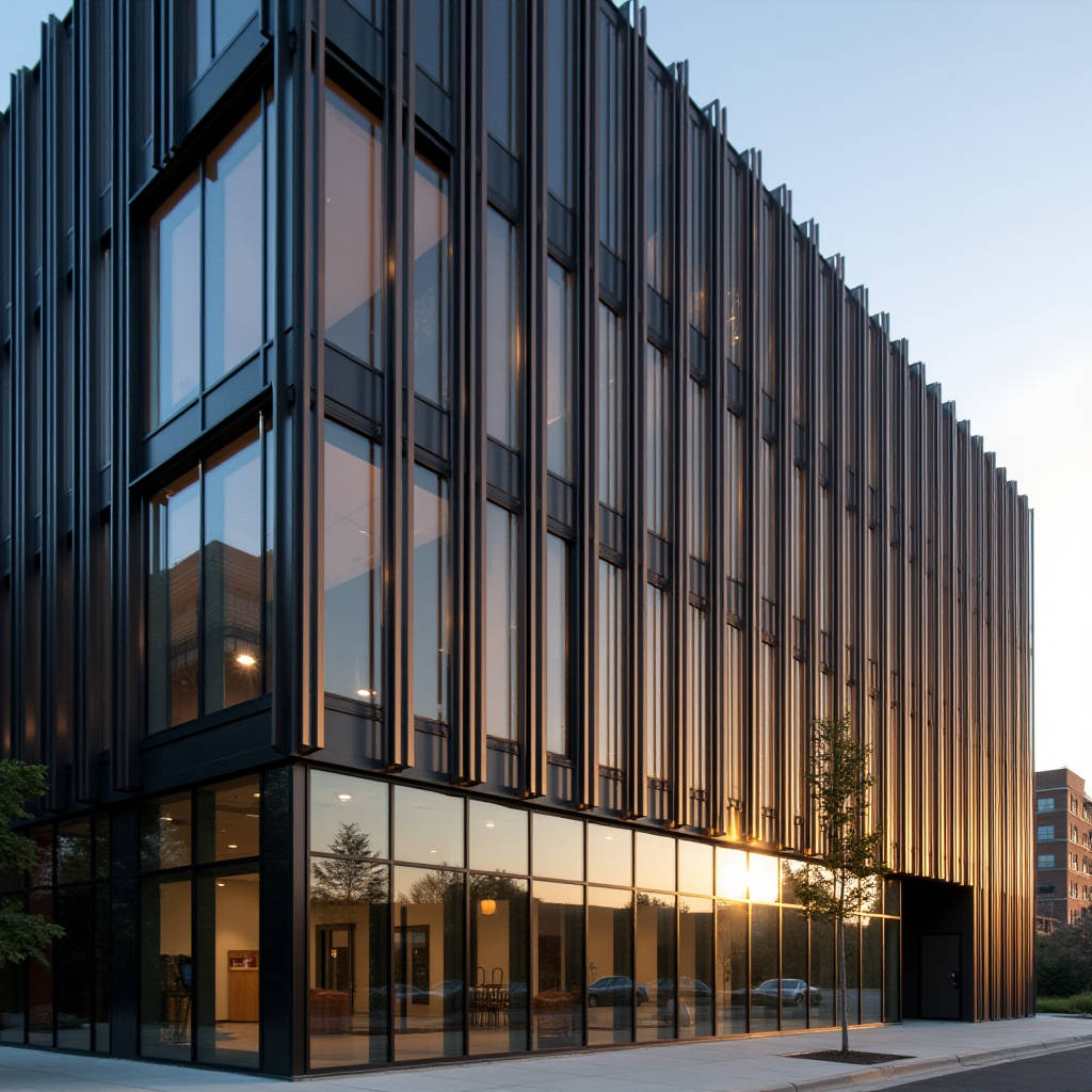
An Aluminum Baffle Facade is not simply a decorative screen hung off a building. For the general contractor and the facade engineer, it represents a distinct structural subsystem where linear aluminium profiles function simultaneously as solar control devices, ventilation screens, and architectural signifiers. The detailing challenge sits at the intersection of three disciplines: thermal movement accommodation, wind load transfer, and geometric alignment across large spans. Getting any one of these wrong means the baffles either rattle in high wind, warp under thermal stress, or drift out of alignment within the first three years. This article examines the structural logic behind vertical and horizontal baffle facades, the connection hardware that makes or breaks an installation, and the fabrication tolerances that separate a system that performs for two decades from one that becomes a liability.
Structural Typology: Vertical vs. Horizontal Baffle Systems
The orientation of an Aluminum Baffle Facade dictates the entire load path. Vertical baffles transfer self-weight axially through the profile to the top and bottom connection brackets. The primary structural demand is buckling resistance under compression, particularly for profiles exceeding 4 meters in length. A 100mm x 50mm x 3.0mm 6063-T6 aluminium rectangular tube spanning 6 meters floor-to-floor carries approximately 8.5 kg per linear meter. At 600mm centers, the dead load per bracket pair is roughly 51 kg — manageable, but only if the bracket design accounts for eccentric loading when wind pressure acts perpendicular to the narrow face of the profile.
Horizontal baffles present a fundamentally different problem. The profile spans horizontally between vertical support mullions, and the self-weight now acts perpendicular to the strong axis. Deflection — not strength — governs the design. A horizontal 150mm x 75mm x 3.0mm aluminium tube spanning 3 meters between supports at 500mm vertical spacing will deflect approximately 4.2mm under self-weight alone, before wind load is even considered. This is within the L/360 deflection limit for architectural components under the IBC, but the visual straightness requirement is typically tighter. Contractors who ignore this distinction end up with visible sag that no amount of site adjustment can fix.
Wind Load Engineering for Baffle Facades
The aerodynamic behavior of an Aluminum Baffle Facade differs substantially from a solid rainscreen. Each baffle acts as a bluff body, shedding vortices at wind speeds above 15 m/s. The critical parameter is the solidity ratio — the ratio of projected baffle area to total facade area. At 50% solidity (typical for 100mm-wide baffles at 200mm centers), the net pressure coefficient is approximately 0.85 to 1.1, depending on corner proximity. This means the baffle system experiences roughly 85-110% of the wind pressure that a solid wall would see at the same location.
ASCE 7-22 provides the framework for calculating design wind pressures. For a 30-meter-tall building in Exposure Category B with a basic wind speed of 45 m/s, the velocity pressure qz at the top of the building is approximately 1.25 kPa. Applying a gust effect factor of 0.85 and a pressure coefficient of 1.0 yields a design pressure of roughly 1.06 kPa. A 100mm-wide baffle at 600mm centers spanning 4 meters must resist a uniformly distributed load of 0.64 kN/m. The connection bracket at each end therefore sees a reaction of 1.28 kN — a number that drives the selection of stainless steel fasteners and the embedment depth in the substrate.
Wind tunnel testing becomes necessary when the facade geometry is irregular, when baffles are arranged in staggered patterns, or when the building exceeds 60 meters. The cost of a wind tunnel study for a single facade element typically ranges from $15,000 to $40,000, but this is a fraction of the liability cost if the system fails. Several projects in coastal Southeast Asia have required full-scale mockup testing at 1.5 times the design pressure, with deflection measured at quarter-span, mid-span, and bracket locations.
Connection Hardware: The Hidden Determinant of System Life
The most common failure mode in an Aluminum Baffle Facade is not the baffle profile itself — it is the connection. Three hardware systems dominate the market:
Adjustable bracket systems use a two-part bracket with slotted holes that allow ±15mm of adjustment in two axes. The bracket body is typically 6061-T6 aluminium with a 5mm wall thickness, and the fasteners are A4-70 (316 grade) stainless steel. The advantage is on-site tolerance absorption; the disadvantage is that each adjustment point is a potential loosening point under cyclic wind loading.
Fixed cleat systems use a simple L-shaped or T-shaped aluminium cleat that bolts directly to the substrate and to the baffle. No adjustment is possible, so the substrate must be installed to within ±3mm of the design plane. This is achievable with unitized curtain wall but difficult with cast-in-place concrete. The payoff is zero maintenance on connections for the life of the building.
Through-rod tension systems thread a stainless steel rod through the center of each baffle, with spacers maintaining the gap between baffles. The rod is tensioned at the top and bottom. This system is primarily used for vertical baffle arrays and can span up to 12 meters without intermediate supports. The rod diameter is typically 12mm to 16mm, and the tension force is set to approximately 60% of the rod's yield strength to ensure it never goes slack under thermal contraction.
Futeng® has supplied baffle systems for projects where the connection design was the deciding factor in specification. In one Southeast Asian airport terminal, the engineering team specified fixed cleat connections with 316 stainless hardware throughout after reviewing the maintenance access constraints — the baffles are 18 meters above the concourse floor, and any connection failure would require a full scaffold erection to address.
Thermal Movement: The Invisible Load Case
Aluminium expands at approximately 23.4 × 10⁻⁶ per degree Celsius. A 6-meter vertical baffle subjected to a 50°C temperature swing (from -10°C winter night to 40°C summer afternoon with solar gain) will change length by 7.0mm. If both ends are rigidly fixed, this movement is converted into compressive or tensile stress. For a 6063-T6 profile with a cross-sectional area of 800mm², a 7mm constrained expansion generates approximately 12.8 kN of force — enough to shear an M8 stainless bolt or buckle the profile.
The engineering solution is to fix one end of each baffle and allow the other end to slide. The sliding connection typically uses a PTFE bearing pad or a slotted hole with a shoulder bolt that permits axial movement while restraining lateral movement. The slot length must be at least 1.5 times the calculated thermal movement to account for installation tolerances. For the 6-meter baffle example, the slot should be a minimum of 10.5mm long.
Contractors in the Middle East face the most extreme conditions, where surface temperatures on dark-colored baffles can reach 85°C. A PVDF-coated dark grey baffle in Riyadh will see a surface temperature swing of 70°C between a January night and a July afternoon. The corresponding movement for a 4-meter baffle is 6.6mm. Specifying the sliding detail correctly is not optional — it is the difference between a facade that stays flat and one that buckles within the first year.
Fabrication Tolerances and Material Specifications
The dimensional stability of an Aluminum Baffle Facade begins at the extrusion press. The relevant standard is EN 12020-2 (or ASTM B221 for the North American market), which specifies tolerances for extruded aluminium profiles. For a 100mm-wide rectangular tube, the width tolerance is ±0.45mm and the wall thickness tolerance is ±0.15mm for a nominal 3.0mm wall. These tolerances compound across an array of 50 baffles: a consistent +0.3mm width error across all baffles shifts the cumulative width by 15mm, which may exceed the adjustment range of the bracket system.
| Parameter | Standard | Requirement | Verification Method |
|---|---|---|---|
| Alloy & Temper | ASTM B221 / EN 755 | 6063-T6 (architectural) or 6061-T6 (structural) | Mill certificate, spectrometer check |
| Wall Thickness | EN 12020-2 | ±0.15mm for 3.0mm nominal | Ultrasonic gauge, 5 points per profile |
| Straightness | EN 12020-2 | Max 0.5mm deviation per 1000mm length | Surface plate + feeler gauge |
| Twist | EN 12020-2 | Max 0.5° per 1000mm length | Dial indicator on surface plate |
| PVDF Coating Thickness | AAMA 2605 | Min 30μm (2-coat), min 40μm (3-coat) | Eddy current gauge, 5 points per face |
| Color Consistency | ASTM D2244 | ΔE ≤ 1.0 (batch), ΔE ≤ 2.0 (batch-to-batch) | Spectrophotometer |
| Cut Length | Project spec | ±1.0mm for lengths ≤ 3m, ±1.5mm for 3-6m | Calibrated tape or laser measure |
| End Squareness | Project spec | ≤ 0.5° from perpendicular | Digital protractor |
The alloy selection warrants attention. 6063-T6 is the default for architectural baffles because it extrudes well and accepts anodizing or PVDF coating with excellent surface quality. Its yield strength is 170 MPa. Where the baffle serves a structural role — for example, a 150mm-deep baffle that also supports a walkway canopy — 6061-T6 with a yield strength of 240 MPa is specified. The cost premium for 6061-T6 is approximately 15-20% on the raw extrusion, but the strength increase is 41%, so the weight-to-strength economics often favor 6061-T6 for long spans.
Coating Systems and Long-Term Weathering
The coating on an Aluminum Baffle Facade is not decorative — it is the primary corrosion barrier. Three coating systems account for over 95% of architectural baffle specifications:
PVDF (Polyvinylidene Fluoride) liquid coating, applied per AAMA 2605, is the benchmark for exterior architectural aluminium. The 70% PVDF resin system (typically Kynar 500® or Hylar 5000®) provides 20+ years of color retention and chalk resistance in most climates. The standard specification is a 3-coat system: primer (5-8μm), color coat (25-30μm), and clear coat (10-15μm), for a total dry film thickness of 40-50μm. The clear coat is essential for metallic and mica finishes because the pigment particles are susceptible to UV degradation without a protective layer.
Powder coating per AAMA 2604 offers a lower-cost alternative with good performance for 10-15 years. The polyester-based powders achieve 60-80μm film thickness in a single coat. The limitation is gloss retention: a 60° gloss reading on a powder-coated baffle will drop from 30 to approximately 15 after 5 years of equatorial sun exposure, while a PVDF-coated baffle will retain 80% of its initial gloss over the same period.
Anodizing per AAMA 611 creates an aluminium oxide layer 15-25μm thick that is integral to the metal surface. Class I anodizing (architectural) is suitable for exterior use. The aesthetic is distinct — a metallic, slightly directional finish that cannot be replicated by paint. The trade-off is limited color range (clear, champagne, bronze, black) and susceptibility to acid rain etching in polluted urban environments.
For coastal installations within 5km of saltwater, PVDF with a chrome-free pretreatment and a minimum 5μm primer is the minimum recommendation. The salt spray resistance per ASTM B117 should exceed 4,000 hours with no blistering and underfilm corrosion less than 2mm from the scribe.
Acoustic Performance of Baffle Facades
An Aluminum Baffle Facade is not inherently an acoustic treatment, but its geometry can be engineered to provide measurable sound absorption. When baffles are spaced at 100-200mm centers and backed by a 50mm mineral wool or acoustic fleece layer, the system functions as a Helmholtz-type absorber. The cavity between the baffle rear face and the backing material determines the tuned frequency.
Laboratory testing per ISO 354 (reverberation room method) shows that a vertical baffle system with 150mm-deep profiles at 150mm centers, backed by 50mm of 60 kg/m³ mineral wool, achieves a weighted sound absorption coefficient αw of 0.65 to 0.75. The absorption peaks in the 500-1000 Hz range, which corresponds to the dominant frequencies of human speech. This makes baffle facades particularly effective for reducing reverberation in atria, transport concourses, and open-plan office lobbies.
The noise reduction coefficient (NRC) can be further improved by perforating the baffle face. A 2.5mm hole diameter at 15% open area, combined with an acoustic fleece behind the perforation, shifts the absorption peak to lower frequencies and increases the NRC to 0.80-0.85. The cost adder for perforation is approximately $25-40 per square meter of baffle face area, and the perforation pattern must be specified before extrusion because post-extrusion drilling is rarely cost-effective for production quantities.
Installation Sequencing and Quality Control
The installation of an Aluminum Baffle Facade follows a sequence that must be coordinated with the main building envelope works. The critical path typically runs through the following stages:
- Substrate survey and datum establishment. A laser survey of the structural substrate (concrete slab edge, steel frame, or curtain wall mullion) establishes the as-built plane. The survey data is compared to the design plane, and any deviation exceeding ±10mm triggers a substrate rectification scope. This step is often skipped on fast-track projects, and the consequences — baffles that cannot be adjusted into alignment — are discovered only during installation.
- Bracket installation and alignment. Brackets are installed to the surveyed positions, with the first and last bracket on each run set as datums. A string line or laser line is used to align intermediate brackets. The tolerance for bracket position is ±2mm in-plane and ±1mm out-of-plane.
- Mockup installation. A minimum of 10 baffles across two full bays is installed as a benchmark. The mockup is inspected for alignment, gap consistency, and bracket engagement. Any issues identified at this stage are resolved before production quantities are installed.
- Production installation. Baffles are installed from the bottom up (for horizontal systems) or from one end to the other (for vertical systems). Each baffle is checked for plumb/level before the next is installed. The gap between adjacent baffles is verified with a go/no-go gauge.
- Final alignment and torque check. All adjustable connections are checked for the specified torque (typically 15-20 Nm for M8 A4-70 bolts). A final visual inspection from multiple viewing angles identifies any baffles that are out of plane.
The quality control documentation for a typical baffle facade project includes material certificates for every heat of aluminium, coating batch test reports, bracket pull-out test results (for anchors in concrete), and a final alignment survey. On projects where Futeng® has supplied the baffle system, the factory provides a digital twin of the as-fabricated geometry — a 3D point cloud or BIM model that the contractor can overlay on the site survey data to identify clashes before installation begins.
Fire Performance and Building Code Compliance
Aluminium itself is non-combustible (Euroclass A1 per EN 13501-1), but the complete baffle system includes components — gaskets, acoustic fleece, thermal breaks — that may not be. The relevant fire performance requirement depends on the building height and occupancy classification.
For buildings over 18 meters in the UK and many Commonwealth jurisdictions, the external wall construction must meet the performance criteria of BS 8414 (large-scale fire test) or the equivalent NFPA 285 in the United States. An Aluminum Baffle Facade with an open-joint design and non-combustible mineral wool insulation behind it typically passes these tests because the open joints prevent the accumulation of combustible gases behind the cladding. The critical detail is the fire stop at each floor level: a horizontal cavity barrier of intumescent material that expands to seal the cavity when exposed to heat, preventing vertical fire spread within the baffle cavity.
Specifiers should request a full system fire test report, not just component-level test data. A system that uses A1-rated aluminium and A1-rated insulation can still fail a BS 8414 test if the bracket design creates a continuous vertical channel that acts as a chimney. The fix is usually a horizontal baffle closure plate at each floor line, which breaks the cavity into compartments no taller than one floor height.
Cost Drivers and Value Engineering
The installed cost of an Aluminum Baffle Facade ranges from $180 to $450 per square meter of facade area, depending on profile complexity, coating specification, and site access conditions. The major cost drivers, in order of impact, are:
- Profile geometry: A custom extrusion die costs $3,000-$8,000 and is amortized over the project quantity. Standard profiles from existing dies eliminate this cost entirely.
- Coating specification: PVDF 3-coat adds approximately $35-55/m² over powder coating. Metallic and mica finishes add a further $10-20/m² due to the required clear coat and tighter process controls.
- Bracket complexity: Adjustable brackets cost 2-3 times more than fixed cleats, and the installation labor is approximately 30% higher due to the alignment process.
- Site access: A baffle facade installed from a mast climber costs 15-25% less per square meter than one installed from a swing stage, because the mast climber provides a stable working platform and faster vertical repositioning.
- Perforation and acoustic treatment: Perforated baffles with acoustic backing add $40-70/m² to the material cost, but may eliminate the need for separate acoustic ceiling treatments, yielding a net saving on the overall project.
Value engineering on a baffle facade typically targets the bracket system first. Switching from fully adjustable to partially adjustable brackets (adjustable in one axis, fixed in the other) can save $15-25/m² while retaining enough adjustment to accommodate typical substrate tolerances. The second target is the baffle spacing: increasing the center-to-center spacing from 150mm to 200mm reduces the number of baffles by 25%, and the corresponding reduction in brackets and installation labor is proportional.
A baffle facade is a system, not a product. The baffle profile is the visible component, but the engineering value lies in the connection design, the thermal movement strategy, and the fabrication tolerances. Selecting a supplier who understands all three is the single decision that most determines whether the installed facade meets the architect's intent and the contractor's program.
The Aluminum Baffle Facade has evolved from a niche architectural feature into a mainstream facade typology. The engineering principles governing its performance — wind load transfer through discrete connection points, thermal movement accommodation through sliding joints, and acoustic absorption through cavity geometry — are well understood but not always well executed. The projects that succeed are those where the contractor, the facade engineer, and the baffle supplier collaborate on the connection design and the installation sequence from the schematic design phase, not after the contract is awarded. For further technical guidance, refer to the AAMA 2605 coating standard, the ASTM B221 extrusion specification, and the ASCE 7-22 wind load provisions. The ISO 354 acoustic test standard and the NFPA 285 fire test provide the performance verification framework for the complete system.