Aluminium Box Louver Structural Engineering Wind Loads Span Tables and Mounting Design
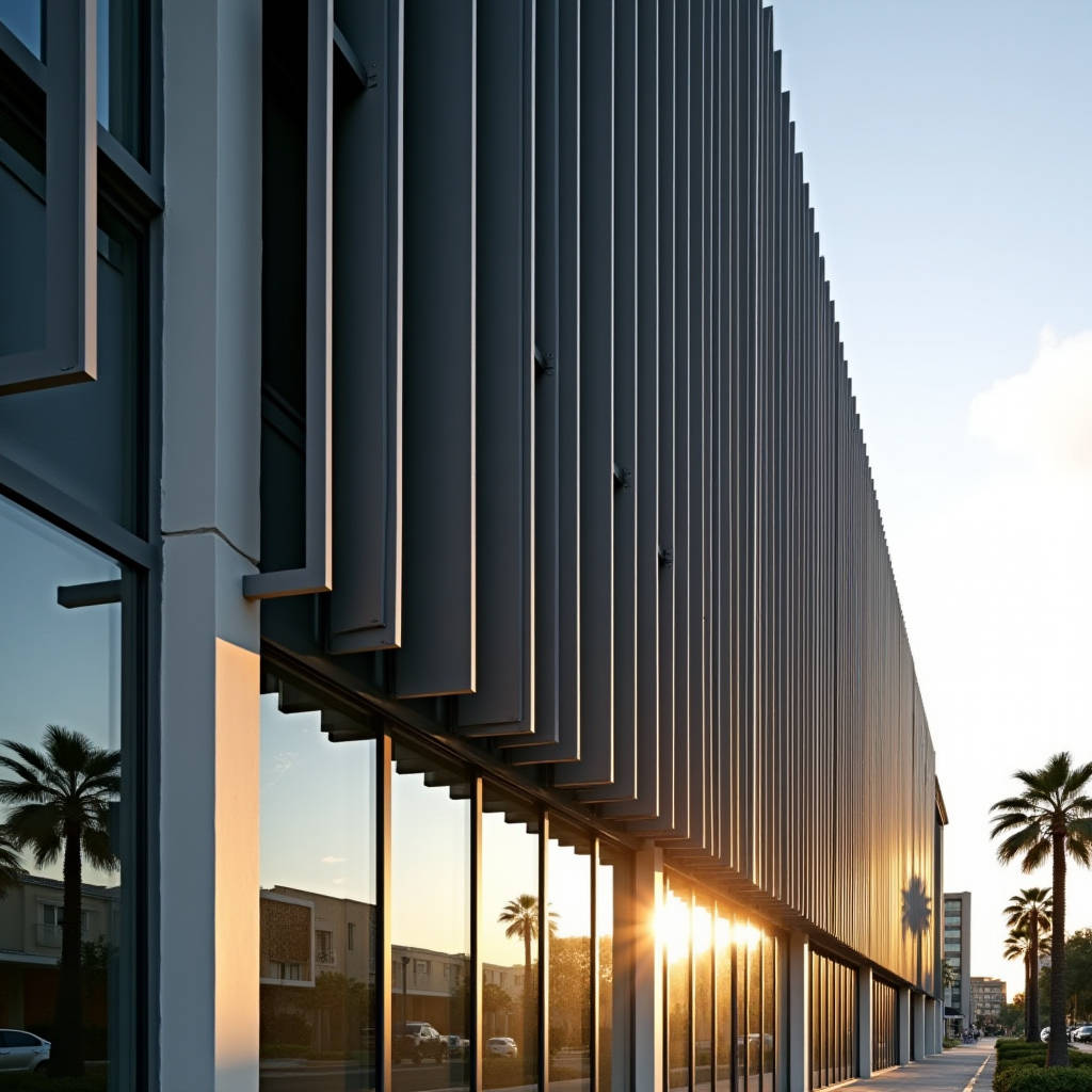
When a facade engineer sits down to size Aluminium Box Louver systems for a high-rise in a typhoon-prone coastal city, the first question rarely concerns aesthetics. It concerns wind. Specifically, how much lateral pressure these hollow extruded blades can absorb before deflecting beyond acceptable limits, and how the mounting substructure transfers that load back to the primary building frame. Aluminium Box Louver assemblies occupy a strange middle ground in facade engineering — they are non-structural in the sense that they do not bear building weight, yet structurally consequential because a failed louver blade at 40 metres above ground becomes a projectile. This article examines the structural logic behind these systems, the engineering assumptions that govern span tables, and the practical decisions that separate a specification that works on paper from one that survives a storm.
What Structural Role Does an Aluminium Box Louver Actually Play
An Aluminium Box Louver is not a cladding panel. It is a linear screening element, typically fabricated from 6063-T5 or 6063-T6 aluminium alloy extrusions, with a hollow rectangular or near-rectangular cross-section. The "box" descriptor refers to the closed geometry of the blade — four sides forming a tube, which provides torsional rigidity that flat plate louvers or single-skin blades cannot match. This matters because wind hitting a louver blade at an oblique angle generates both bending and twisting forces. The closed box section resists torsion far better than an open C-channel or Z-profile, which is why box louvers dominate specifications for buildings above 20 metres in height.
The structural function splits into three layers. First, the blade itself acts as a simply supported or continuously supported beam spanning between vertical mullions or horizontal rails. Second, those mullions or rails transfer accumulated point loads to the primary structure via brackets and anchors. Third, the entire assembly must accommodate thermal movement — aluminium expands at roughly 0.024 mm per metre per degree Celsius, and a 4-metre blade subjected to a 50°C temperature swing will grow by nearly 5 mm. Ignoring this in the detailing phase leads to creaking, buckling, or fastener fatigue that no amount of PVDF coating can fix.
Wind Load Calculations That Actually Matter
Most curtain wall consultants reference AS/NZS 1170.2, ASCE 7-16, or EN 1991-1-4 depending on the project's jurisdiction. The critical parameter for Aluminium Box Louver design is not the basic wind speed but the net pressure coefficient — how much of that wind actually translates into force on a porous screen. Louvers are not solid walls. Air passes through the gaps between blades, which reduces the total pressure differential. However, the reduction is not uniform across all wind angles. At 0° incidence (wind blowing perpendicular to the facade), the porosity effect is significant. At 45° to 60° incidence, the blades partially shield each other and the net pressure on individual blades can actually increase due to funnelling effects.
A practical rule of thumb used by engineers in Southeast Asia and the Middle East: for a typical Aluminium Box Louver with 50% free area, design for 60-70% of the code-specified wind pressure for a solid wall of the same dimensions. But this is a starting point, not a substitute for wind tunnel testing or CFD analysis on complex geometries. The table below summarises the key differences between wind load assumptions for solid cladding versus louvered screens.
| Parameter | Solid Aluminium Cladding (2.5mm Sheet) | Aluminium Box Louver (50% Free Area) |
|---|---|---|
| Net pressure coefficient (Cp,net) | 1.0 - 1.4 (solid wall) | 0.4 - 0.8 (porous screen, angle-dependent) |
| Design wind pressure (kPa) at 40m height, 45 m/s | 1.8 - 2.2 kPa | 0.9 - 1.5 kPa (varies with solidity ratio) |
| Load path behaviour | Uniformly distributed across panel face | Concentrated on blade edges, transferred to mullions |
| Deflection limit (typical) | L/175 or 19mm max | L/180 to L/240 (stricter due to visual alignment) |
| Fatigue consideration | Low (stiff sheet, minimal cyclic loading) | Moderate (blade vibration, vortex shedding risk) |
| Thermal expansion allowance | 2-3mm per panel joint | 3-5mm per blade end, depending on length |
Span Tables and the Limits of Extrusion Geometry
Every Aluminium Box Louver manufacturer publishes span tables. The numbers vary significantly because they depend on three variables that are rarely standardised across the industry: the alloy temper, the section modulus of the specific extrusion profile, and the allowable deflection criterion the manufacturer has chosen. A 150mm x 50mm box section in 6063-T6 with a wall thickness of 2.0mm might span 2.4 metres at a given wind load according to one supplier, while another rates the same profile at 2.0 metres because they use a stricter L/240 deflection limit instead of L/180.
What makes this genuinely complicated is the interaction between the blade's self-weight and wind loading. A horizontally oriented Aluminium Box Louver spanning 3 metres between supports will sag under its own weight before any wind touches it. The dead load deflection must be subtracted from the allowable total deflection to determine how much capacity remains for wind. For vertical blade orientations, self-weight deflection is negligible, but the eccentricity of the mounting bracket introduces a torsional moment that many simplified span tables ignore entirely.
Engineers who specify these systems regularly should request the full section properties — moment of inertia (Ix, Iy), section modulus (Zx, Zy), and torsional constant (J) — and run independent checks rather than relying solely on manufacturer tables. The American Architectural Manufacturers Association (AAMA) provides test methods under AAMA 450 for voluntary performance rating of louver systems, and referencing these standards in specifications adds a layer of quality assurance that generic "manufacturer to certify" clauses do not.
Mounting Systems: Where Most Failures Begin
The blade itself rarely fails. What fails is the connection. An Aluminium Box Louver blade is only as reliable as the bracket, bolt, and anchor that hold it to the building. The typical mounting configuration uses extruded aluminium cleats or stainless steel brackets fixed to the back of the blade with self-tapping screws or through-bolts, which then connect to vertical mullions or directly to the substrate. Each connection point introduces a stress concentration, and in a corrosive environment — coastal, industrial, or both — that stress concentration becomes a corrosion initiation site.
Three common failure modes observed in forensic facade investigations:
- Galvanic corrosion at the steel-to-aluminium interface. Even with stainless steel fasteners, if the isolating washer or bush is omitted or degrades, the aluminium acts as a sacrificial anode. The blade wall thins around the fastener hole until the bearing capacity collapses.
- Pull-out failure of anchors in concrete. Louver mullions are often fixed to slab edges with expansion anchors or chemical anchors. Edge distance, concrete strength, and crack status all affect capacity. A 100mm slab edge with anchors too close to the edge is a recurring problem in retrofit projects where the original structure was not designed for louver loads.
- Fatigue cracking at bracket welds. Some systems use welded aluminium brackets. The heat-affected zone around the weld has reduced strength compared to the parent metal. Under cyclic wind loading — particularly in regions with frequent storms — cracks initiate at the weld toe and propagate through the bracket.
For projects where the Aluminium Box Louver system spans floor-to-floor, a continuous mullion design with thermal breaks at each floor level is strongly recommended. The mullion itself becomes a structural element that must be sized for combined bending and axial loads, and the connection to the slab must allow for vertical movement while restraining horizontal wind loads. This is standard curtain wall engineering, but the louver industry often sits outside the curtain wall supply chain, and the interface detailing between the two trades is a frequent source of coordination gaps.
Coating Performance Under Structural Strain
PVDF (polyvinylidene fluoride) coatings dominate the architectural aluminium market for good reason. A properly applied PVDF system — typically a three-coat or four-coat system with a total dry film thickness of 30-40 microns — delivers colour retention and chalk resistance that polyester powders cannot match over a 20-year service life. The relevant standard is AAMA 2605, which specifies minimum performance requirements for superior-performing organic coatings on aluminium extrusions and panels.
But there is a structural dimension to coating selection that is rarely discussed. When an Aluminium Box Louver blade deflects under wind load, the coating on the tension face stretches. A brittle coating cracks. A flexible coating — and PVDF is inherently more flexible than polyester — accommodates the strain without micro-cracking. This matters because a cracked coating exposes the aluminium substrate to moisture, and while aluminium's natural oxide layer provides some protection, it is not sufficient in aggressive environments. The interaction between structural deflection and coating integrity is why some specifications now explicitly require coating adhesion and flexibility testing per ASTM D3359 and ASTM D522 after the coating has been subjected to accelerated weathering.
For coastal projects, some engineers are now specifying a marine-grade pretreatment — typically a chromate conversion coating or a titanium-zirconium-based alternative — under the PVDF topcoat. This adds cost but significantly extends the service life of Aluminium Box Louver assemblies within 500 metres of breaking surf. Suppliers like Futeng® who operate their own PVDF coating lines can integrate this pretreatment into the production workflow without the logistical complications of sending extrusions to a third-party coater.
AAMA 450 and the Case for Third-Party Testing
AAMA 450-20, "Voluntary Standard for Performance Rating of Louvers," provides a framework for testing louver assemblies for structural performance, water penetration, and wind-driven rain resistance. It is not a mandatory code requirement in most jurisdictions, but it is increasingly referenced in performance specifications for commercial and institutional projects in North America and the Middle East.
The structural test under AAMA 450 involves mounting a representative louver assembly in a test rig and applying uniform static pressure in both positive and negative directions. Deflection is measured at multiple points, and the assembly is inspected for permanent deformation after the load is removed. The standard also includes a cyclic test for fatigue evaluation. The key output is a pressure rating — typically expressed in Pascals or pounds per square foot — that the specifier can compare directly against the project's design wind pressure.
What AAMA 450 does not do is account for the cumulative effect of thermal cycling combined with wind loading. A louver that passes a static pressure test at 21°C may behave differently at 60°C, when the aluminium has softened slightly and the thermal expansion has altered the preload in the fasteners. This is not a criticism of the standard — no single test can replicate every real-world condition — but it is a reminder that test reports are a minimum baseline, not a guarantee of performance in every scenario.
Free Area, Pressure Drop, and the Mechanical Engineer's Perspective
Aluminium Box Louver specification is not solely a facade engineer's domain. The mechanical engineer responsible for the building's HVAC system cares deeply about the louver's free area because it directly affects air intake and exhaust performance. A louver with 50% free area might seem adequate on paper, but if the blades are profiled in a way that creates turbulence and pressure drop, the effective free area can be significantly lower than the geometric free area.
The coefficient of discharge (Cd) quantifies this difference. A well-designed Aluminium Box Louver with aerodynamically shaped blades can achieve a Cd of 0.30 to 0.40, meaning the effective free area is 30-40% of the gross opening. Poorly designed louvers with flat blades and sharp edges can drop below 0.20. For a mechanical engineer sizing an air handling unit, the difference between 0.20 and 0.35 Cd translates directly into fan energy consumption over the building's operating life. The Air Movement and Control Association (AMCA) provides standardised test methods for louver performance under AMCA 500-L, and specifying louvers tested to this standard gives the mechanical engineer reliable data for system design.
The structural and ventilation requirements can pull in opposite directions. Increasing blade depth improves structural span capacity but reduces free area. Increasing blade spacing improves free area but reduces shading effectiveness and may compromise the visual solidity the architect wants. The resolution is always project-specific and requires the facade engineer, mechanical engineer, and architect to sit in the same room — or at least on the same video call — and negotiate the trade-offs explicitly.
Fire Performance: A Topic That Demands Precision
Aluminium melts at approximately 660°C. This is a fact, not a design flaw. In a fully developed compartment fire, external Aluminium Box Louver blades will melt if flame impingement is direct and sustained. The question for the fire engineer is whether the louver system contributes to fire spread, and whether its presence affects the performance of other fire safety systems.
In the UK and markets that follow British Standards, external louver systems on buildings above 18 metres are subject to the requirements of BS 8414 and BR 135 for fire propagation performance. The aluminium blades themselves are classified as A1 (non-combustible) under EN 13501-1, but the system as a whole — including gaskets, thermal breaks, and any polymeric components — must be tested as an assembly. The critical detail is the cavity barrier: where the louver system creates a cavity between itself and the building envelope, that cavity must be fire-stopped at each floor level and at compartment boundaries to prevent vertical fire spread.
In the Middle East, civil defence authorities increasingly require full-scale facade fire tests for any external cladding or louver system on buildings over 15 metres. This is a direct response to the Grenfell Tower fire and subsequent regulatory tightening across the GCC. Specifying Aluminium Box Louver systems with non-combustible components and documented fire test data is no longer optional in these markets — it is a prerequisite for permit approval.
Practical Engineering Recommendations
An Aluminium Box Louver specification is a series of interconnected decisions. Changing the blade profile changes the structural span. Changing the span changes the mullion size. Changing the mullion size changes the anchor loads. Changing the anchor loads may require a different fixing method. The engineer who treats these decisions as independent risks producing a specification that looks coherent on paper but cannot be built.
The most reliable approach, based on projects that have performed well over 10 to 15 years of service, is to start with the wind load, work outward to the blade geometry, then to the mounting system, and only then to the finish and colour. The structural logic drives the specification. The aesthetic decisions — blade pitch, colour, texture — are layered on top of a system that already works structurally. Reversing this order — choosing a blade profile for its appearance and then trying to make it work structurally — is the root cause of a significant proportion of louver system failures.
For procurement managers and quantity surveyors, the cost structure of an Aluminium Box Louver package breaks down roughly as 40-50% for the extruded blades (material and fabrication), 20-25% for the mounting system and fixings, 15-20% for the coating, and 10-15% for installation. The temptation to reduce cost by specifying thinner blade walls or fewer mullions is understandable but shortsighted. The incremental cost of upgrading from a 2.0mm to a 2.5mm wall thickness, or from 6063-T5 to 6063-T6 temper, is modest compared to the cost of replacing a failed system — and negligible compared to the reputational cost of a louver failure on a prominent building.