Aluminum Box Louver Bracket Engineering Thermal Loads and Corrosion Risk in High Rise Facades
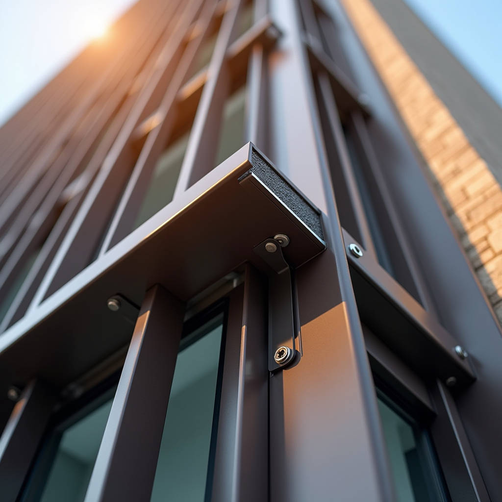
A facade is only as strong as the logic behind its joints. Aluminum Box Louver systems have become a staple in modern commercial envelopes, but the conversation around them rarely moves past blade pitch and color selection. The real engineering weight falls on the connection between the louver assembly and the primary structure — specifically, the bracketry, the thermal isolation strategy, and the wind load path. When a contractor in Singapore or Dubai orders a batch of Aluminum Box Louver panels for a 40-story tower, the first question should not be about the profile depth. It should be about how the box section transfers lateral loads into the mullion without creating a thermal bridge that condenses into a leak two years later. This article picks apart the bracket engineering behind Aluminum Box Louver installations, digs into the numbers on galvanic corrosion in mixed-metal interfaces, and lays out the fabrication tolerances that separate a clean sightline from a punch-list disaster.
Why the Bracket Defines the Louver
Extruded aluminum box sections are straightforward. A 150mm by 40mm hollow profile with 2.0mm wall thickness, mill-finish or PVDF-coated, punched to accept a blade at a fixed angle — the manufacturing process is well understood. The bracket is where projects go sideways. An Aluminum Box Louver assembly mounted on a high-rise in Kuala Lumpur faces a completely different set of mechanical demands than the same profile mounted on a ground-level parking structure in Melbourne. Wind suction on the leeward side of a tall building can reverse the load direction on the bracket entirely, turning what was designed as a compression connection into a tension connection. If the bracket was engineered only for dead load and a uniform positive pressure, the first monsoon season exposes the gap.
Bracket design for Aluminum Box Louver systems typically falls into three categories: face-fixed cleats, continuous angle rails, and stand-off blade brackets. Face-fixed cleats are the simplest — a small L-shaped aluminum extrusion fastened to the back of each box section and anchored to the substrate. They work for low-rise applications where the louver span stays under 1.2 meters. Continuous angle rails run horizontally behind the louver field and tie into the structure at 600mm to 900mm centers. This is the standard for mid-rise and high-rise work. Stand-off brackets introduce a gap between the louver and the structural face, which is essential when the building envelope includes external insulation or a rainscreen cavity. Each approach changes the thermal performance, the installation speed, and the long-term fatigue behavior of the Aluminum Box Louver system.
Thermal Bridging and the Stainless Steel Decision
Aluminum conducts heat roughly 1,600 times more efficiently than air. When an Aluminum Box Louver bracket penetrates the insulation layer and bolts directly to a steel or concrete substrate, the bracket becomes a thermal highway. In cold climates, the interior face of the bracket drops below the dew point, condensation forms, and the resulting moisture migrates into the wall assembly. In hot climates, the same bridge pulls heat inward, adding to the cooling load. The fix is a thermal break — a polyamide or fiberglass-reinforced nylon isolator pad inserted between the bracket and the substrate. But the break introduces a new problem: the bolt that passes through the bracket, the isolator, and into the substrate is still metal, and it still conducts.
This is where stainless steel enters the conversation. A common specification for Aluminum Box Louver brackets in corrosive environments — coastal zones, industrial areas, anywhere with airborne chlorides — is 316-grade stainless steel. The material choice triggers a galvanic compatibility question. Aluminum and stainless steel are far apart on the galvanic series, with a potential difference of roughly 0.5 to 0.7 volts depending on the specific alloy. In the presence of an electrolyte — rainwater, condensation, salt spray — the aluminum becomes the anode and sacrifices itself. The rate of corrosion depends on the surface area ratio. A large aluminum bracket with a small stainless bolt is a manageable scenario. A small aluminum bracket with a large stainless washer is a corrosion risk that accelerates fast.
| Bracket Material | Fastener Material | Galvanic Risk Level | Required Isolation | Typical Application |
|---|---|---|---|---|
| 6063-T5 Aluminum | 304 Stainless Steel | Moderate | Nylon washer + sleeve | Urban, inland |
| 6063-T5 Aluminum | 316 Stainless Steel | High | Full isolation kit | Coastal, industrial |
| 6063-T5 Aluminum | HDG Steel | Very High | Not recommended | Avoid |
| 6061-T6 Aluminum | 316 Stainless Steel | High | Full isolation kit + EPDM gasket | Marine, offshore |
| 6063-T5 Aluminum | Aluminum (6000 series) | Negligible | None required | All climates |
The table above is a starting point for specification, not a final answer. Actual galvanic risk depends on the time of wetness, the chloride deposition rate, and the quality of the isolation detailing. A project in Doha with zero rainfall but high humidity and frequent dust storms can see more corrosion than a project in Vancouver with 1,200mm of annual rain, simply because the dust holds moisture against the metal surface for longer periods. The safest approach for Aluminum Box Louver installations in any environment where the bracket-to-substrate connection involves dissimilar metals is a full isolation kit: a nylon or EPDM washer under the bolt head, a nylon sleeve through the bracket hole, and a nylon washer under the nut. The incremental cost per connection is under $0.50, and the alternative is a warranty claim that costs a hundred times more.
Wind Load: The Numbers That Drive Bracket Spacing
Wind load calculation for Aluminum Box Louver systems follows the same code framework as any cladding element — ASCE 7 in the United States, EN 1991-1-4 in Europe, AS/NZS 1170.2 in Australia and New Zealand — but the louver geometry introduces a nuance. A solid aluminum panel experiences wind as a uniform surface pressure. A box louver experiences wind as a combination of pressure on the blade faces and flow through the openings. The net pressure coefficient depends on the free area ratio. A louver with 50% free area does not experience 50% of the wind load; the relationship is nonlinear, and the actual reduction is closer to 30% to 40% depending on the blade profile and angle.
Consider a typical Aluminum Box Louver installation on a 100-meter-tall building in a coastal city with a basic wind speed of 45 m/s (3-second gust). The velocity pressure at the top of the building, accounting for the exposure category and the topographic factor, might be around 1.8 kPa. With a net pressure coefficient of 1.2 for a partially open louver, the design pressure on the louver face is roughly 2.2 kPa. A single box section spanning 1.5 meters between brackets, with a face width of 150mm, sees a line load of about 0.33 kN/m. That is a modest number, but the bracket itself sees a concentrated reaction of around 0.25 kN at each support point. The bracket must resist this load in bending, shear, and pull-out from the substrate.
The bracket manufacturer should provide a load table that correlates bracket spacing with allowable wind pressure. A well-engineered Aluminum Box Louver bracket in 6063-T5 aluminum, 5mm thick, with a 50mm stand-off, might be rated for 1.5 kN per bracket in tension and 2.0 kN in shear. The limiting factor is often the pull-out capacity of the anchor into the substrate, not the bracket itself. In concrete, a single M10 stainless steel expansion anchor in 30 MPa concrete has a pull-out capacity of roughly 4 to 6 kN, which provides a comfortable safety factor. In a steel stud backup wall, the numbers drop dramatically, and the bracket spacing must tighten accordingly.
Fabrication Tolerances and the Sightline Problem
Architects specify Aluminum Box Louver systems for the clean, continuous horizontal or vertical lines they create across a facade. The reality on site is that a 2mm deviation in bracket placement, multiplied across 50 brackets on a single elevation, produces a visible wave in the louver line. The human eye can detect a deviation of 3mm over a 3-meter sightline. On a 30-meter facade, the cumulative tolerance stack from bracket fabrication, bracket installation, and louver profile straightness must be held under 5mm total deviation from the reference plane. That is a demanding standard for a system assembled from extruded aluminum components that arrive on site in 6-meter lengths.
The tolerance chain starts at the extrusion die. A 6063-T5 aluminum box section extruded to a 150mm by 40mm profile has a dimensional tolerance of ±0.5mm on the width and ±0.3mm on the wall thickness per Aluminum Association extrusion standards. The bracket, whether extruded or fabricated from sheet, adds another ±0.5mm. The anchor placement in the substrate adds ±2mm in practice, even when the specification calls for ±1mm. The solution is not to tighten every tolerance to an impossible degree but to design adjustability into the bracket connection. Slotted holes, shim packs, and a two-stage installation sequence — rough-set the brackets, sight the line, then final-torque — are standard practice for high-end Aluminum Box Louver work.
Futeng® has addressed this tolerance challenge in several large-scale projects by supplying pre-assembled bracket-and-louver modules that are factory-jigged to a tolerance of ±0.5mm before shipping. The approach shifts the alignment work from the scaffold to the factory floor, where controlled conditions and dedicated jigs produce a more consistent result. The trade-off is higher shipping volume and a more complex logistics chain, but for projects where the architectural sightline is non-negotiable, the math works out.
Coating Systems and the Bracket Interface
The conversation about Aluminum Box Louver finishes usually centers on the visible face — PVDF versus powder coat, gloss level, color consistency under different light angles. The bracket interface is where the coating conversation gets practical. A PVDF coating applied to AAMA 2605 standards delivers 30-plus years of color retention and chalk resistance on the visible louver face. But the bracket is bolted to the back of the louver, and the bolt head bears directly on the coated surface. Under cyclic wind loading, the bolt head micro-frets against the coating. Over time, the coating wears through at the contact point, exposing bare aluminum. In a coastal environment, that is the starting point for filiform corrosion, which creeps under the coating and lifts it from the metal.
The standard mitigation is a nylon or EPDM washer between the bolt head and the coated surface. A more robust approach is to mask the bolt contact area before coating, leaving a bare aluminum pad that is then protected by the bolt and washer assembly with a generous application of a neutral-cure silicone sealant around the fastener penetration. The sealant is not structural — it is a moisture barrier. The specification should call for a neutral-cure silicone, not an acetoxy-cure, because the acetic acid released during acetoxy curing attacks the aluminum surface and can initiate pitting before the louver is even installed.
Powder coating to AAMA 2604 standards is a cost-effective alternative for inland applications where UV exposure is the primary concern and salt spray is not a factor. The film thickness is typically 60 to 80 microns, compared to 30 to 40 microns for PVDF. The thicker film provides better abrasion resistance at the bracket contact point, but the organic resin system is less UV-stable over decades. For a parking structure in Phoenix, powder coat on an Aluminum Box Louver system makes sense. For a beachfront hotel in Miami, PVDF is the minimum defensible specification.
Thermal Movement and the Long Span
Aluminum expands at roughly 23 micrometers per meter per degree Celsius. A 6-meter Aluminum Box Louver section installed at 20°C that sees a surface temperature of 70°C on a summer afternoon — entirely plausible for a dark-colored PVDF finish in direct sun — will grow by about 7mm. If the brackets at both ends are fixed rigidly, the louver buckles. If the brackets are too loose, the louver rattles. The engineering solution is a combination of fixed and sliding connections. One bracket on each louver section is fixed in all directions; the remaining brackets allow axial movement through slotted holes oriented parallel to the louver span.
The slot length must accommodate the full thermal movement range plus a safety margin. For a 6-meter section with a design temperature range of -20°C to +80°C, the total movement is about 14mm. The slot should be 16mm to 18mm long to allow for installation tolerance on top of thermal movement. The bolt in the sliding connection is tightened to a torque that allows movement under thermal load but prevents movement under wind load. That torque value is typically 50% to 70% of the full tightening torque for the bolt size, and it should be verified on a mock-up before the installation team goes to the main facade.
Installation Sequence and Quality Control
The best-engineered Aluminum Box Louver bracket is useless if the installation crew installs it backward. The sequence starts with a surveyed grid on the substrate. Every bracket position is marked from a common datum, not from the adjacent bracket, to avoid cumulative error. The first row of brackets is installed and checked for alignment with a string line or a laser level. The first louver section is placed, and the alignment is checked again before the remaining brackets are tightened. This is the point where the project either stays on track or starts accumulating errors that will be visible from the street.
AAMA TIR-A9-14 provides a framework for field testing metal curtain wall components, and the principles apply directly to Aluminum Box Louver installations. The standard recommends a minimum of one water penetration test per 100 square meters of facade area, conducted at a static pressure differential of 300 Pa for 15 minutes. For louver systems specifically, the test should include the bracket penetrations, not just the louver-to-louver joints.
Quality control for Aluminum Box Louver installations should include a pull-out test on a sample of anchors, a torque check on a sample of bracket fasteners, and a visual inspection of the isolation detailing at every bracket location. The cost of these checks is trivial compared to the cost of removing and replacing a louver field that has corroded or shifted out of alignment. On a project with 2,000 brackets, a 5% sample for torque verification and a 1% sample for pull-out testing is a reasonable minimum. The results should be documented and submitted as part of the close-out package.
Specifying the Right Bracket for the Right Climate
Climate zone drives bracket selection more than any other single factor. The table below summarizes the bracket configuration recommendations for four common climate scenarios, based on field experience across multiple international projects and guidance from ISO 9223 on atmospheric corrosivity classification.
| Climate Zone | Corrosivity Category | Bracket Material | Isolation | Coating |
|---|---|---|---|---|
| Inland, dry (e.g., Denver, Madrid) | C1-C2 | 6063-T5 Aluminum | None required | Powder coat AAMA 2604 |
| Urban, temperate (e.g., London, Chicago) | C2-C3 | 6063-T5 Aluminum | Nylon washer | PVDF AAMA 2605 |
| Coastal, subtropical (e.g., Singapore, Miami) | C3-C4 | 6061-T6 Aluminum | Full isolation kit | PVDF AAMA 2605, 3-coat |
| Marine, industrial (e.g., Doha, offshore) | C4-C5 | 6061-T6 + 316 SS inserts | Full isolation + EPDM | PVDF AAMA 2605, 4-coat |
These recommendations align with the performance requirements outlined in AAMA 2605 for coating durability and the structural principles of ASTM E330 for wind load resistance. The key takeaway is that the bracket is not a commodity item. It is a climate-specific engineered component that determines whether the Aluminum Box Louver system performs for 30 years or becomes a maintenance liability in five.
Cost Realities in Bracket Engineering
The bracket assembly typically represents 8% to 15% of the total Aluminum Box Louver system cost, depending on the complexity of the stand-off, the material grade, and the isolation requirements. That percentage sounds small, but the bracket is the component most likely to trigger a failure. A project that saves $2,000 by specifying a thinner bracket or omitting the thermal break can generate a $50,000 remediation bill if the louvers shift, corrode, or leak. The cost-risk equation is straightforward: spend on the bracket now, or spend much more later.
For a mid-rise commercial building with 500 square meters of Aluminum Box Louver coverage, the total system cost — louvers, brackets, fasteners, isolation, and installation — typically falls between $180 and $350 per square meter, depending on the region, the profile complexity, and the finish specification. The bracket portion of that cost is $15 to $50 per square meter. Upgrading from a basic face-fixed cleat to a thermally broken continuous rail with full isolation might add $20 per square meter. On a 500-square-meter project, that is $10,000. The alternative — replacing a corroded louver field after five years — costs $150,000 in materials, labor, access equipment, and business interruption. The math is not complicated.
The specification should also account for the substrate condition. A concrete substrate with embedded steel plates for welding brackets is the ideal scenario — fast, strong, and thermally manageable with the right isolator. A steel stud backup wall with screw-fixed brackets is the reality on most commercial projects, and it demands a different approach: more brackets per linear meter, smaller stand-off distances, and careful attention to the screw pull-out values published by the stud manufacturer. The ASTM C1513 standard for cold-formed steel framing provides design values that should be referenced in the specification.
The Aluminum Box Louver bracket is an engineered connection point that carries the entire wind load, thermal load, and dead load of the louver assembly. It operates in a corrosive interface zone, it must accommodate thermal movement, and it must be installed to a tolerance that satisfies an architectural sightline. The specification should address the bracket material, the isolation strategy, the anchor type, the coating compatibility, the thermal movement accommodation, and the installation sequence. A specification that says only "brackets by louver manufacturer" is a specification that invites a dispute. The industry has the standards, the test data, and the field experience to do better. The question is whether the project team applies them before the louvers go up, or after the first complaint comes in.