Aluminium Aerofoil Louver Engineering Wind Load Span and Coating Performance for Facade Systems
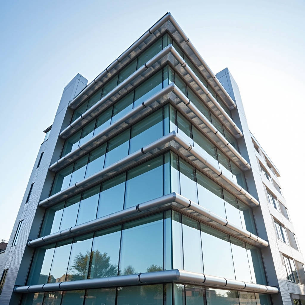
Aluminium Aerofoil Louver systems have become a defining element in modern facade engineering, not merely as decorative appendages but as high-performance solar shading components that directly influence a building's thermal envelope. When a project moves from schematic design to shop drawings, the conversation shifts from aesthetics to hard numbers: wind load resistance, span capabilities, deflection limits, and finish durability. This article focuses on the structural and performance engineering behind extruded aluminium aerofoil louvers, with particular attention to how blade geometry, alloy selection, and mounting configuration determine whether a system performs reliably across a 30-year service life in coastal or high-wind environments.
Why Aerofoil Geometry Matters Beyond Appearance
The elliptical profile of an aluminium aerofoil louver is not a stylistic whim. It is a deliberate engineering choice rooted in fluid dynamics. Unlike flat or rectangular blades, the aerofoil shape reduces wind resistance by allowing air to flow smoothly around the profile rather than hitting a flat face and generating turbulence. This matters for two reasons: first, it reduces the actual wind load transferred to the supporting substructure, which can translate into lighter and more economical mullion and bracket designs. Second, the streamlined shape minimizes vortex shedding, a phenomenon where alternating low-pressure zones behind a bluff body cause oscillation. In tall buildings, vortex-induced vibration can fatigue connections over time. The aerofoil profile mitigates this at the source.
From a shading performance standpoint, the curved leading edge of an aerofoil blade creates a larger effective shading surface relative to its projected width. A 200mm aerofoil blade, depending on its elliptical geometry, can deliver shading performance comparable to a wider flat louver because the curvature captures and redirects low-angle morning and afternoon sun more effectively. This is particularly relevant for east- and west-facing facades where solar gain peaks during oblique sun angles.
Alloy Selection and Temper: 6063-T5 vs. 6063-T6
Nearly all extruded aluminium aerofoil louvers on the market use 6063 alloy, but the temper designation is where procurement decisions get made or broken. 6063-T5 is air-cooled from the extrusion temperature and artificially aged. It offers good extrudability and surface finish quality, making it suitable for standard-span applications up to approximately 2.5 metres. 6063-T6 undergoes solution heat treatment followed by artificial aging, yielding roughly 30% higher tensile strength (minimum 215 MPa vs. 160 MPa for T5). For spans exceeding 3 metres or for installations in wind zones above 2.0 kPa design pressure, T6 temper is strongly recommended.
The trade-off is cost and lead time. T6 profiles require additional heat treatment cycles and may have slightly higher rejection rates for surface defects. For projects where the architect specifies a high-gloss PVDF finish, T5 material with its finer grain structure can sometimes produce a superior visual result. The specification writer needs to balance structural demand against aesthetic requirements. A reputable extrusion supplier such as Futeng® can provide mill test certificates and section property data for both tempers, allowing the facade engineer to run deflection calculations before committing to a purchase order.
Wind Load Calculations and Span Tables
Wind load is the governing design criterion for aluminium aerofoil louver systems. The calculation methodology follows the principles laid out in ASCE 7-22 or EN 1991-1-4, depending on the project jurisdiction. The key parameters are basic wind speed, exposure category, building height, and the aerodynamic shape factor of the louver profile. For an aerofoil section, the shape factor is typically lower than for a rectangular hollow section, but it is not negligible. Values between 0.8 and 1.2 are common, depending on the specific elliptical geometry and the angle of attack.
Once the design wind pressure is established, the engineer calculates the bending moment on the louver blade treated as a simply supported beam. The section modulus of the aluminium extrusion is the critical geometric property. Wider blades (300mm, 400mm, 600mm) have inherently higher section moduli and can span further, but they also present a larger projected area to the wind, increasing the applied load. This is not a linear relationship, and span tables must be generated for each specific profile.
A practical rule of thumb: for a 200mm aerofoil blade in 6063-T5 with a design wind pressure of 1.5 kPa, the maximum span with deflection limited to L/175 is approximately 2.8 metres. Upgrading to T6 temper extends this to roughly 3.4 metres. For a 400mm blade under the same conditions, spans of 4.5 to 5.0 metres are achievable. These are indicative figures only; project-specific calculations must account for end fixity conditions, whether the blade is simply supported or has some rotational restraint at the brackets.
Finish Systems: PVDF vs. Powder Coating for Exterior Louvers
The coating specification for aluminium aerofoil louvers is not a matter of colour preference. It directly affects long-term colour retention, gloss stability, and resistance to chalking in UV-intense environments. The two dominant technologies are liquid PVDF (polyvinylidene fluoride) coatings conforming to AAMA 2605 and architectural-grade polyester powder coatings conforming to AAMA 2604 or Qualicoat Class 2.
PVDF coatings, typically 70% PVDF resin with 30% acrylic or other modifying resins, offer superior resistance to UV degradation. Accelerated weathering tests show that PVDF-coated aluminium retains over 50% of its original gloss after 10 years of Florida exposure, while standard polyester powder coatings may drop below 30% gloss retention within 5 to 7 years. For coastal projects, PVDF also provides better resistance to salt spray when applied over a proper chromate conversion coating. The film thickness for PVDF on extruded profiles should be minimum 30 microns as a two-coat system, or 40 microns for a three-coat system with a clear topcoat.
Powder coating has improved significantly. Super-durable polyester powders meeting AAMA 2604 can achieve 5-year Florida gloss retention above 50%, and some formulations now approach PVDF performance at a lower cost. The application process for powder on complex aerofoil profiles requires careful attention to Faraday cage effects in electrostatic spraying, particularly in the concave areas of the elliptical shape. A poorly applied powder coat can have thin spots that become corrosion initiation sites.
| Property | PVDF (AAMA 2605) | Super-Durable Powder (AAMA 2604) | Standard Polyester Powder |
|---|---|---|---|
| Minimum Film Thickness | 30-40 microns | 60-80 microns | 60-80 microns |
| 10-Year Florida Gloss Retention | 50-65% | 35-50% | 15-30% |
| Salt Spray Resistance (ASTM B117) | 4,000+ hours | 2,000-3,000 hours | 1,000-1,500 hours |
| Colour Range | Limited; solid and mica | Extensive; textured options | Extensive |
| Relative Cost Index | 1.0 (baseline) | 0.65-0.80 | 0.45-0.60 |
| Typical Warranty | 20-30 years | 10-15 years | 5-10 years |
Mounting Configurations and Structural Brackets
The interface between the aluminium aerofoil louver blade and the building structure is the most failure-prone part of any installation. Three primary mounting configurations dominate the market: horizontal continuous, vertical continuous, and individual bay-mounted panels. Each imposes different load paths on the supporting brackets.
Horizontal louvers are typically supported at each end by aluminium or stainless steel brackets anchored to vertical mullions or directly to the slab edge. The brackets must resist both gravity loads (dead weight of the louver) and wind loads acting perpendicular to the blade face. For long horizontal runs, intermediate support brackets are required at intervals determined by the span capacity of the blade. A common oversight is specifying brackets that are strong enough for the vertical reaction but lack sufficient torsional stiffness to prevent blade rotation under wind uplift.
Vertical aerofoil fins present a different challenge. Gravity acts axially along the fin, so the bottom support bracket carries the full compressive load of the fin's self-weight. For a 6-metre vertical fin in 400mm width, the self-weight can exceed 30 kg, and the bottom bracket must be designed as a load-bearing seat rather than a simple locator. Thermal expansion and contraction must also be accommodated. A 6-metre aluminium extrusion will expand by approximately 4mm over a 50°C temperature swing. If both ends are rigidly fixed, buckling can occur. The standard detail is to fix the bottom and allow the top to slide within a guide bracket.
Thermal Performance and Solar Heat Gain Coefficient
An aluminium aerofoil louver system reduces solar heat gain through two mechanisms: direct shading of the glazing and indirect reduction of the exterior surface temperature of the facade. The Solar Heat Gain Coefficient (SHGC) of a glazing system with external louvers can be reduced by 40% to 70% depending on blade spacing, projection depth, and orientation.
The key geometric parameter is the ratio of blade spacing to blade depth. A 1:1 ratio (e.g., 300mm blade depth with 300mm centre-to-centre spacing) provides approximately 50% shading at normal incidence but drops off significantly at oblique angles. For east and west facades where low-angle sun is the primary concern, a ratio of 1:1.5 or even 1:2 may be necessary. The aerofoil shape provides an advantage here because the curved profile maintains a larger effective shading area at oblique angles compared to a flat blade of the same projected width.
Building energy modelling tools such as EnergyPlus or IES VE can incorporate the exact geometry and reflectance properties of the louver system. The reflectance of the coating matters: a high-reflectance PVDF finish in a light colour can reflect 70-80% of incident solar radiation, reducing the heat re-radiated from the louver itself to the glazing behind it. Dark-coloured louvers absorb more solar energy and can reach surface temperatures 20-30°C above ambient, creating a secondary heat source near the glazing.
Corrosion Considerations for Coastal and Industrial Environments
Aluminium has inherent corrosion resistance due to its self-passivating oxide layer, but this does not make it immune to degradation in aggressive environments. For aluminium aerofoil louver installations within 5 kilometres of a coastline, additional protective measures are necessary. The combination of chloride ions from sea spray and the galvanic potential between aluminium and any dissimilar metal fasteners can initiate pitting corrosion.
The first line of defence is alloy selection. 6063 alloy with controlled copper content (below 0.10%) offers good marine corrosion resistance. The second is the pretreatment: a chromate conversion coating per ASTM D1730 or a chromium-free alternative such as titanium-zirconium conversion coating provides an excellent base for the organic topcoat. The third is isolation: all stainless steel fasteners (grade 316 minimum for coastal) must be isolated from the aluminium with nylon washers or bushings to break the galvanic circuit.
For extremely aggressive environments such as offshore platforms or chemical processing facilities, anodized finishes per AAMA 611 (Class I, 18 microns minimum) can be specified instead of or in addition to organic coatings. Anodizing creates a hard aluminium oxide layer that is integral to the metal surface, eliminating the risk of under-film corrosion that can affect organic coatings if they are scratched.
Fire Performance and Building Code Compliance
External aluminium aerofoil louvers fall under the scrutiny of building fire codes, particularly in high-rise construction where the spread of flame across the facade is a critical safety concern. Aluminium itself is non-combustible (Euroclass A1 per EN 13501-1), but the coating system and any polymer gaskets or seals must also be evaluated.
In jurisdictions following the International Building Code (IBC) or NFPA 285, external facade components above a certain height must demonstrate that they do not contribute to vertical flame propagation. While solid aluminium panels are inherently non-combustible, the louver assembly as a system—including brackets, gaskets, and any thermal breaks—must be tested or assessed by a qualified fire engineer. PVDF coatings, being fluoropolymer-based, have inherently low flame-spread characteristics and do not sustain combustion independently.
For projects in the UK and Middle East, compliance with BS 8414 or equivalent large-scale facade fire tests may be required. Specifiers should request fire performance data from the louver manufacturer and ensure that the complete assembly, not just the aluminium extrusion, meets the relevant code requirements.
Supply Chain and Quality Control for International Projects
Procuring aluminium aerofoil louvers for a major international project involves more than comparing unit prices. The extrusion process itself has quality variables: die condition affects dimensional tolerance, quench rate affects mechanical properties, and ageing oven temperature uniformity affects temper consistency across a production batch.
Key quality control documents to request include mill test certificates for chemical composition and mechanical properties (per EN 755 or ASTM B221), dimensional inspection reports for each die run, and coating performance test reports (film thickness, gloss, colour difference, adhesion, and impact resistance). For PVDF coatings, the resin supplier certification confirming the 70% PVDF content is essential. Counterfeit or low-PVDF coatings have been a documented problem in the industry, and independent laboratory verification of coating composition is a prudent step for high-value projects.
Lead times for custom aerofoil extrusions typically range from 4 to 8 weeks, depending on die manufacturing, billet availability, and finishing queue. Standard profiles in common widths (100mm, 150mm, 200mm, 300mm) may be available from stock or with shorter lead times. Packaging for sea freight deserves attention: aerofoil profiles are prone to surface damage if not properly separated with protective interleaving. Wooden crates with foam-lined dividers are the industry standard for export shipments.
Integration with Solid Aluminium Cladding Panels
On many contemporary facades, aluminium aerofoil louvers are installed alongside solid aluminium cladding panels to create a cohesive architectural language. The technical interface between these two systems requires coordination. The louver support brackets are often anchored to the same vertical mullions that carry the panel framing system. The bracket design must accommodate the thickness of the panel system (typically 2.5mm or 3.0mm solid aluminium sheets with PVDF finish) and any insulation or waterproofing layers behind it.
Thermal movement compatibility is another consideration. The solid aluminium panels and the extruded louver profiles, both being aluminium, have the same coefficient of thermal expansion (approximately 23 × 10⁻⁶/°C). This simplifies joint design because both elements move at the same rate. However, if the supporting steel substructure is used, the differential expansion between steel (12 × 10⁻⁶/°C) and aluminium must be accommodated with slotted connections or elastomeric bearings.
From a visual standpoint, matching the PVDF coating colour and gloss between extruded louvers and sheet aluminium panels requires coordination between the extrusion coater and the panel coater. Even when both use the same paint code, differences in substrate texture (extruded vs. rolled sheet) and application method can produce perceptible variations. A mock-up panel incorporating both elements, reviewed under natural daylight, is the only reliable way to verify colour harmony before full production begins.
Practical Engineering Recommendations
Based on the technical analysis presented, several engineering recommendations emerge for specifiers and facade contractors working with aluminium aerofoil louver systems. First, invest in project-specific wind load calculations rather than relying on generic span tables. The interaction between blade geometry, building aerodynamics, and local wind climate is too complex for rule-of-thumb approaches. Second, specify 6063-T6 temper for any span exceeding 3 metres or any project in a wind zone above 2.0 kPa. The incremental cost is modest relative to the risk of inadequate performance. Third, for coastal installations, insist on PVDF coating with full documentation of pretreatment and resin content, and use 316-grade stainless steel fasteners with proper isolation from the aluminium.
The selection of an aluminium aerofoil louver system is fundamentally an engineering decision with long-term performance implications. Getting the alloy, temper, coating, and mounting details right at the specification stage prevents costly remediation later. Manufacturers with documented quality systems and a track record of supplying international projects provide the most reliable path to a successful installation.
For further technical reference, consult the American Architectural Manufacturers Association (AAMA) for coating specifications, ASTM International for material testing standards, and ISO for quality management frameworks applicable to aluminium extrusion production.