Aluminum Aerofoil Louver Engineering Guide Span Tables Coating Specs and Wind Load Performance
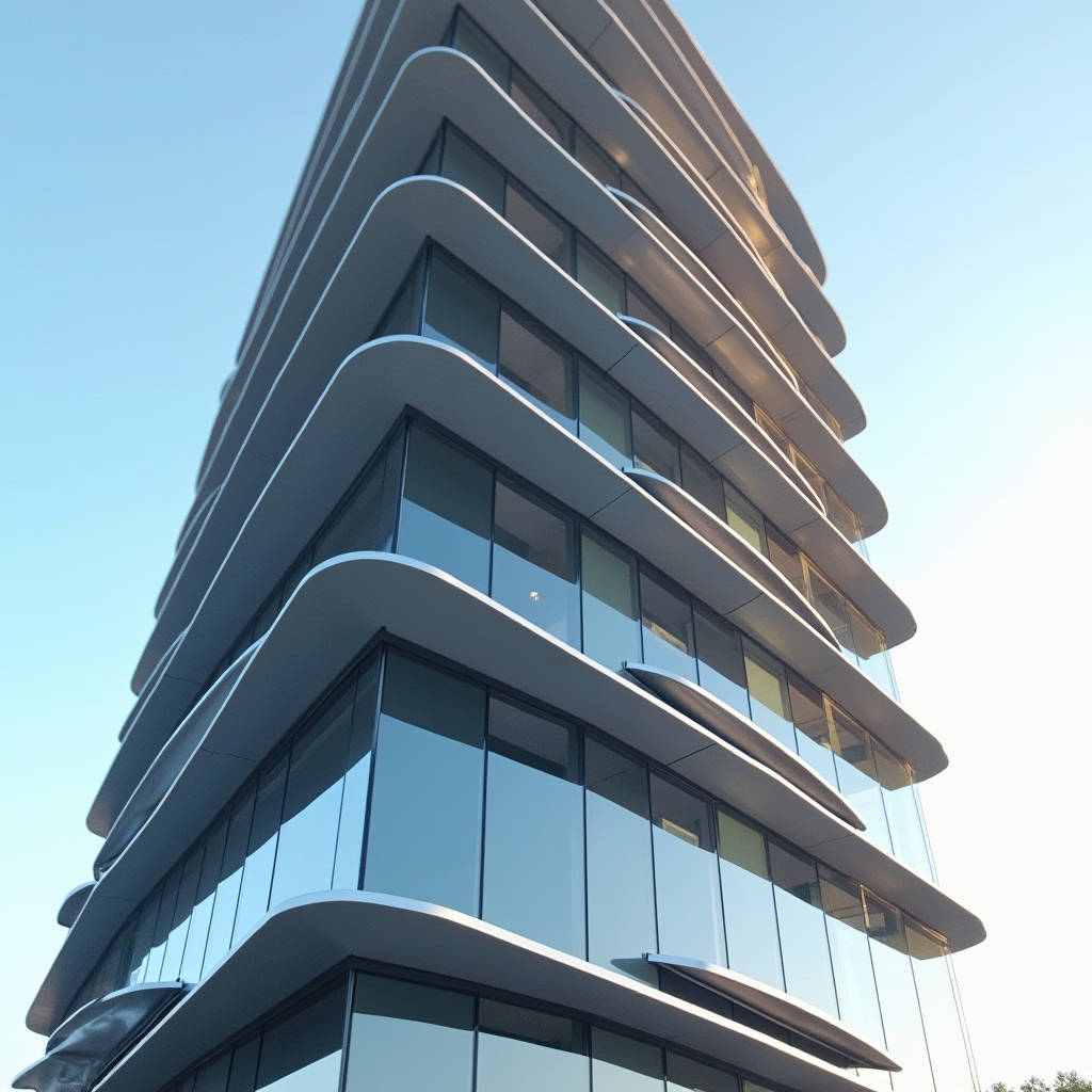
When specifying sun control elements for a curtain wall facade, the Aluminum Aerofoil Louver stands apart from conventional rectangular shading systems through its wing-shaped profile geometry. This streamlined cross-section does more than look refined — it reduces wind resistance, minimizes vortex shedding, and allows longer unsupported spans compared to flat or Z-blade louvers of equivalent weight. For facade engineers and procurement managers evaluating shading solutions for high-rise commercial towers, transportation hubs, or healthcare facilities, understanding how aerofoil geometry translates into quantifiable structural and thermal performance is the difference between a specification that works on paper and one that performs under real wind loads. This article examines the engineering logic behind the aerofoil profile, the structural implications of span-to-deflection ratios, and the fabrication tolerances that determine whether an extruded aluminum louver system delivers on its architectural promise.
Why the Aerofoil Shape Matters Structurally
The defining characteristic of an Aluminum Aerofoil Louver is its asymmetric elliptical cross-section — thicker at the leading edge and tapering to a narrow trailing edge. This is not an aesthetic choice. The profile distributes bending stress along a curve rather than concentrating it at corners, which is exactly what happens with rectangular hollow sections. When wind hits a flat blade face-on, the pressure distribution is uneven, creating localized stress peaks near the mounting brackets. An aerofoil blade, by contrast, allows airflow to separate gradually along its curved surface, reducing the pressure differential between the windward and leeward sides.
From a structural engineering standpoint, this means the moment of inertia (I-value) of an aerofoil section is inherently higher than a flat plate of the same material weight. A 150mm-wide aerofoil extrusion with a 2.5mm wall thickness can typically achieve a section modulus 25-35% higher than a rectangular louver blade of equivalent mass. For the specifier, this translates directly into longer allowable spans between support brackets — often 1,800mm to 2,400mm for a 150mm blade under moderate wind loads — which reduces the number of vertical mullions or horizontal transoms required in the support structure. Fewer brackets mean lower material cost, faster installation, and cleaner sightlines.
Wind Load Performance and Span Tables
Wind load governs louver span limits. The governing standard for most international projects is ASCE 7 (Minimum Design Loads for Buildings and Other Structures), which provides wind speed maps and pressure coefficients. For an Aluminum Aerofoil Louver installed on a building above 30 meters, the design wind pressure can easily exceed 1.5 kPa in coastal or typhoon-prone regions. The blade must resist this pressure without exceeding a deflection limit — typically L/180 for visual straightness or L/360 where adjacent glazing or cladding interfaces demand tighter tolerances.
Manufacturers like Futeng® provide span tables derived from finite element analysis (FEA) and verified by physical load testing. These tables correlate blade width, wall thickness, alloy grade, and support spacing to maximum allowable wind pressure. A representative dataset for a 200mm aerofoil blade in 6063-T6 alloy with 2.0mm wall thickness might show:
- Support spacing 1,500mm: allowable wind pressure 2.8 kPa at L/180 deflection
- Support spacing 2,000mm: allowable wind pressure 1.6 kPa at L/180 deflection
- Support spacing 2,500mm: allowable wind pressure 0.9 kPa at L/180 deflection
These numbers shift considerably with alloy selection. Switching from 6063-T5 to 6063-T6 increases yield strength from approximately 145 MPa to 170 MPa, gaining roughly 15% in allowable span for the same deflection limit. For projects in hurricane zones, 6061-T6 (yield strength ~240 MPa) is sometimes specified, though the extrusion cost rises by 20-30% and lead times may extend due to billet availability.
Wind tunnel testing per ASCE 49-21 can provide project-specific pressure coefficients that are often more favorable than code-default values, potentially reducing the number of support brackets by 10-15% for complex facade geometries.
Extrusion Tolerances and Fabrication Precision
The performance of an Aluminum Aerofoil Louver system depends as much on manufacturing precision as on profile design. Extrusion tolerances are governed by standards such as EN 755-9 (for European projects) and ANSI H35.2 (for North American specifications). For a typical 150mm to 300mm aerofoil blade, the critical tolerance dimensions include:
- Cross-section width: ±0.5mm to ±0.8mm depending on profile size
- Wall thickness: ±0.15mm for walls under 3.0mm
- Straightness: 0.5mm per 300mm of length, maximum 2.0mm over 6 meters
- Twist: 0.5° per 300mm, maximum 3.0° over full length
These tolerances become critical when louvers are installed in continuous horizontal runs across multiple bays. A 6-meter blade with 2.0mm of bow will create a visible gap inconsistency at the joint with the adjacent blade. For architects specifying tight joint gaps — 10mm or less — the straightness tolerance must be tightened to 1.0mm over 6 meters, which requires stretcher-leveling after extrusion and adds approximately 8-12% to the blade cost.
End cap fabrication is another area where precision matters. Aerofoil blades are typically cut to length and fitted with die-cast or fabricated aluminum end caps that close the hollow profile. The end cap must match the aerofoil contour within 0.3mm to avoid a visible step at the joint. For PVDF-coated blades, end caps are often coated separately and installed after the main blade is mounted, which requires careful batch matching of the coating color. AAMA 2605-compliant PVDF coatings exhibit slight color variation between batches — typically ΔE ≤ 1.0 — and this variation becomes visible when end caps and blades come from different coating runs.
Coating Systems and Long-Term Weathering
Architectural Aluminum Aerofoil Louver systems are almost always specified with a high-performance coating. The dominant standards are AAMA 2605 (superior performance) and AAMA 2604 (high performance), both applicable to PVDF fluoropolymer coatings. The choice between them affects warranty duration, color retention, and chalk resistance.
| Property | AAMA 2604 (High Performance) | AAMA 2605 (Superior Performance) |
|---|---|---|
| Minimum PVDF resin content | 50% | 70% |
| Color retention (10-year ΔE) | ≤ 5.0 | ≤ 3.0 |
| Chalk resistance (10-year) | Rating 6 (ASTM D4214) | Rating 8 (ASTM D4214) |
| Typical warranty | 15-20 years | 20-30 years |
| Coastal suitability | Moderate (≥3km from shore) | Excellent (≥500m from shore) |
| Relative cost | Base | +25-35% |
For projects within 500 meters of breaking surf, AAMA 2605 is effectively mandatory. The higher PVDF resin content provides superior resistance to chloride ion penetration, which otherwise causes filiform corrosion at cut edges and fastener holes. Powder coating — typically polyester TGIC or super-durable polyester per Qualicoat Class 2 — is an alternative for inland applications where UV exposure is the primary concern rather than salt spray. Powder coat offers a lower cost point (roughly 60-70% of AAMA 2605 PVDF) but with a shorter warranty period of 10-15 years.
Anodizing is occasionally specified for Aluminum Aerofoil Louver applications, particularly where a metallic natural finish is desired. However, anodized finishes on large-format aerofoil blades present challenges: color consistency across 6-meter lengths is difficult to maintain, and the anodic layer is brittle, making it susceptible to micro-cracking if the blade is subjected to torsional stress during handling or installation. For most commercial projects, PVDF remains the default specification.
Thermal Performance and Solar Control Logic
The solar control function of an Aluminum Aerofoil Louver is quantified by its shading coefficient (SC) and the related solar heat gain coefficient (SHGC) of the combined glazing-and-shading assembly. The aerofoil profile's curved geometry provides a subtle advantage: the rounded leading edge reduces the angle-dependent reflectivity that can cause glare issues with flat-blade louvers. When the sun is at a low angle, a flat blade can reflect a concentrated beam into adjacent buildings or ground-level public spaces. The aerofoil's curved surface diffuses this reflection over a wider angle, reducing peak luminance.
The shading effectiveness depends primarily on blade spacing and projection depth. A common rule of thumb: the blade spacing (center-to-center) should not exceed 1.5 times the blade projection from the facade for effective solar cut-off at a 45° altitude angle. For a 200mm-deep aerofoil blade, this means a maximum spacing of 300mm. Tighter spacing improves shading but reduces daylight admission and outward visibility — a trade-off that must be resolved during the schematic design phase.
For projects pursuing LEED or BREEAM certification, the energy modeling should account for the louver system's impact on cooling load reduction. A well-designed external aerofoil shading system can reduce peak cooling load by 15-25% for east- and west-facing glazed facades in temperate climates, and by 25-40% in hot-arid climates according to data published by the ASHRAE technical committee on fenestration performance. These reductions directly affect HVAC equipment sizing and can offset a portion of the louver system's capital cost through reduced chiller capacity.
Installation Configurations and Structural Interfaces
Aluminum Aerofoil Louver systems are installed in three primary configurations: horizontal (blades spanning between vertical mullions), vertical (blades spanning between horizontal transoms), and cantilevered (blades projecting from a single mounting point). Each configuration imposes different structural demands on the supporting facade system.
Horizontal installations are the most common for sun shading on south-facing facades in the Northern Hemisphere. The blades run east-west, and the support brackets transfer dead load, wind load, and any snow/ice load back to vertical mullions. The bracket design must accommodate thermal movement: a 6-meter aluminum blade will expand and contract approximately 8-10mm over a 70°C temperature range (from -20°C to +50°C). Fixed-end brackets at both ends can induce buckling if this movement is not accommodated. The standard solution is a fixed bracket at one end and a sliding bracket at the other, with an elongated slot that permits longitudinal movement.
Vertical installations are common on east- and west-facing facades and for architectural feature elements. The blades run vertically, and the primary structural challenge is resisting wind-induced torsion. Because the aerofoil shape is asymmetric, wind from an oblique angle can generate a twisting moment that the end connections must resist. This is typically addressed by using a bracket that engages both the leading and trailing edges of the profile, rather than a single-point connection at the center of the blade.
For cantilevered installations — where blades project horizontally from a vertical support without a far-end connection — the allowable projection is limited by the profile's torsional stiffness. A 150mm aerofoil blade in 6063-T6 can typically cantilever 800-1,000mm before deflection or torsional rotation becomes visually objectionable. Beyond this, internal steel stiffeners or external tie rods are required.
Material Specifications and Alloy Selection
The standard alloy for extruded Aluminum Aerofoil Louver profiles is 6063, which offers an excellent balance of extrudability, surface finish quality, and mechanical properties. Within the 6063 family, temper selection matters:
- 6063-T5: Cooled from extrusion temperature and artificially aged. Yield strength ~145 MPa. Suitable for most architectural applications with moderate wind loads. Lowest cost.
- 6063-T6: Solution heat-treated and artificially aged. Yield strength ~170 MPa. Preferred for longer spans or higher wind load regions. Approximately 8-12% cost premium over T5.
- 6061-T6: Higher-strength alloy with yield strength ~240 MPa. Used for extreme spans, hurricane zones, or where blade dimensions are constrained. Higher cost (20-30% premium) and slightly coarser surface finish, which may be visible under certain lighting conditions with metallic coatings.
The extrusion billet composition also affects anodizing response. For projects specifying an anodized finish, the aluminum must meet the requirements of AA-M10C22A41 (formerly AA-C22A41) for architectural anodizing quality. Impurities in the billet — particularly iron and silicon — can cause streaking or color inconsistency in the anodized layer. Reputable extruders like Futeng® source billets with controlled composition specifically for architectural applications where surface appearance is critical.
Cost Drivers and Procurement Strategy
The cost of an Aluminum Aerofoil Louver system is driven by five primary factors: alloy and temper, coating specification, blade dimensions, bracket complexity, and project location. Understanding these drivers helps procurement managers make informed trade-offs.
Blade cost is typically quoted per linear meter or per square meter of facade coverage. A 200mm-wide aerofoil blade in 6063-T5 with AAMA 2604 PVDF coating might cost $45-60 per linear meter for a mid-size project (500-2,000 linear meters). Moving to AAMA 2605 adds $12-18 per linear meter. Increasing blade width from 200mm to 300mm adds roughly 35-45% to the blade cost due to the larger extrusion die, higher billet consumption, and increased coating surface area.
Bracket costs are often underestimated. A typical support bracket for a 200mm aerofoil blade — fabricated from 5mm aluminum plate with stainless steel fasteners — costs $8-15 per bracket depending on complexity. With brackets spaced at 1,800mm, a 100-meter facade run requires approximately 56 brackets per horizontal row. For a 10-story building with three rows of louvers per floor, that is 1,680 brackets — a significant line item that should be explicitly priced rather than buried in a lump-sum installation cost.
Freight and logistics deserve attention. Aerofoil blades are typically shipped in 6-meter lengths, which requires flatbed or specialized rack transport. For international projects, 6-meter lengths may exceed standard container dimensions, requiring open-top or flat-rack containers at a premium of 50-80% over standard 40-foot container rates. Some suppliers offer blades in 3-meter lengths for containerized shipping, but this doubles the number of end joints and increases bracket count. The logistics cost trade-off must be evaluated on a project-specific basis.
Quality Verification and Testing Protocols
Before accepting delivery of an Aluminum Aerofoil Louver system, specifiers should establish a quality verification protocol. Key checks include:
- Dimensional verification: Random sample of 5% of blades measured for width, wall thickness, straightness, and twist against the specified tolerances.
- Coating thickness: Measured with a calibrated eddy-current gauge per ASTM D7091. AAMA 2605 requires a minimum dry film thickness of 30μm (1.2 mils) for a two-coat system and 40μm (1.6 mils) for a three-coat system.
- Coating adhesion: Cross-hatch test per ASTM D3359, Method B. Rating 4B or 5B is acceptable.
- Color verification: Measured with a spectrophotometer against the approved color sample. ΔE should not exceed 1.0 for AAMA 2605.
- Gloss level: Measured at 60° geometry per ASTM D523. Should match the specified gloss range (typically 25-35 for a medium-gloss architectural finish).
For large projects, it is advisable to request a mock-up installation of at least three full-length blades with brackets, installed on a representative section of the support structure. This reveals fit-up issues, bracket alignment tolerances, and visual appearance under natural lighting conditions that cannot be assessed from small samples.
Integration with Facade Systems
Aluminum Aerofoil Louver systems must interface with the primary facade structure — typically unitized curtain wall, stick-built curtain wall, or rainscreen cladding. The interface detail is critical for waterproofing and thermal performance. Brackets that penetrate the facade plane create potential water ingress points and thermal bridges.
The preferred approach is to coordinate bracket locations with the curtain wall mullion grid so that brackets attach directly to mullions rather than to spandrel panels or glazing units. Where brackets must attach to slab edges, the waterproofing membrane must be dressed around the bracket and sealed with a compression gasket. Thermal break pads — typically 5-10mm thick PVC or nylon isolators — should be installed between the aluminum bracket and the steel embed to minimize thermal bridging and galvanic corrosion risk.
For unitized curtain wall systems, the louver brackets should ideally be pre-attached to the unit frames in the factory rather than installed on-site. This improves quality control and reduces installation time on the building. However, it requires precise coordination of bracket locations with the structural engineer's embedment layout and the architect's aesthetic intent — a coordination effort that pays dividends in reduced site labor and fewer punch-list items.
The engineering logic behind the Aluminum Aerofoil Louver is straightforward: the wing-shaped profile reduces wind resistance, increases structural efficiency, and delivers solar control with a refined architectural appearance. The specification decisions that determine success — alloy selection, coating standard, bracket design, and tolerance management — are all quantifiable engineering choices rather than subjective preferences. For project teams evaluating these systems, the priority should be obtaining project-specific span tables backed by FEA or physical testing, verifying extrusion tolerances against the specified joint widths, and ensuring that the coating specification matches the project's environmental exposure and service life expectations. Getting these fundamentals right at the specification stage avoids costly remediation after installation.