Aluminium Facade Fin Structural Design Wind Load Brackets and Profile Selection
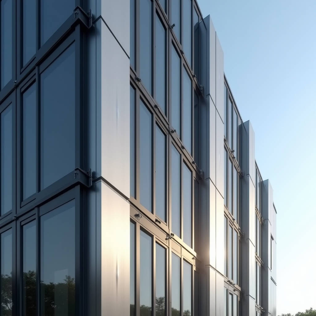
When a facade engineer sits down to calculate wind loads on an Aluminium Facade Fin system, the first question is rarely about aesthetics. It is about the numbers: how much pressure can the fin profile withstand before it deflects beyond acceptable limits, and what happens at the bracket connection points when a storm pushes 150 km/h gusts against the building envelope. An Aluminium Facade Fin is not a passive decorative strip. It is a cantilevered structural element bolted to a primary framework, and every millimeter of its projection from the facade plane amplifies the bending moment at the anchor. Getting the structural calculation right determines whether the fins remain straight and true for 20 years or start vibrating and cracking within the first monsoon season. This article focuses on the structural engineering dimension of aluminium fin facades, covering load path analysis, profile geometry selection, bracket design, and the fabrication tolerances that separate a reliable system from a liability.
Understanding the Load Path in Aluminium Facade Fin Systems
The structural behavior of an Aluminium Facade Fin begins with a simple mechanical reality: it is a cantilever beam subjected to distributed wind pressure. The load travels from the fin face through the aluminium profile, into the connection bracket, through the thermal break and adjustment mechanism, and finally into the primary structural frame of the building. Each interface in this chain introduces potential failure modes. At the fin-to-bracket connection, the bolts experience combined shear and tension. At the bracket-to-substrate interface, the anchors must resist pull-out forces that increase proportionally with the fin's projection depth. A fin projecting 400 mm from the facade generates roughly four times the base moment of a 100 mm projection under identical wind pressure, assuming the same tributary width.
The governing standard for wind load calculation on building cladding in most international projects is ASCE 7-22 for the United States and EN 1991-1-4 for European markets. Both standards require the designer to determine the design wind pressure based on basic wind speed, exposure category, building height, and the specific location of the fin on the facade. Corner zones typically experience negative pressure coefficients 1.5 to 2.5 times higher than the field area, meaning fins installed near building edges must be engineered to a substantially higher standard. A common mistake in value-engineered projects is applying the same fin profile and bracket specification across the entire facade without accounting for zone-dependent pressure variation.
Profile Geometry and the Section Modulus Equation
The resistance of an Aluminium Facade Fin to bending is governed by its section modulus, a geometric property that depends on the cross-sectional shape. Rectangular solid fins offer the highest section modulus per kilogram of material but come with significant weight penalties. Hollow extruded profiles with internal ribbing achieve approximately 70-80% of the bending stiffness of a solid section at 40-50% of the weight. This makes them the preferred choice for deep projections exceeding 300 mm.
The critical calculation for any fin profile is the deflection check under serviceability wind load. Most project specifications limit deflection to L/175 or L/180 of the span, where L is the unsupported length between brackets. For a 3-meter fin span with brackets at 1.5-meter centers, the allowable deflection under service wind load is approximately 8.3 mm. Exceeding this threshold does not necessarily mean structural failure, but it can cause visible misalignment, rattling noises, and long-term fatigue at the connections. The aluminium alloy selection plays a direct role here. Alloy 6063-T6, commonly used for extruded architectural fins, has a yield strength of approximately 170 MPa and an elastic modulus of 69 GPa. Alloy 6061-T6 pushes the yield strength to roughly 240 MPa, providing a 40% increase in load-bearing capacity for the same profile geometry, though at a higher material cost.
Futeng® has supplied solid aluminium fin profiles in 6061-T6 for several high-wind coastal projects where the additional strength margin was non-negotiable. The alloy choice must be specified at the procurement stage because it affects not only structural performance but also the extrusion die design and the anodizing or PVDF coating process parameters.
Bracket Design: The Hidden Structural Bottleneck
If the fin profile is the visible element, the bracket is where most structural problems originate. A typical Aluminium Facade Fin bracket consists of a vertical blade that connects to the fin and a horizontal base plate that anchors to the facade substructure. The bracket material is almost always aluminium, but the grade matters. Brackets machined from 6061-T6 plate or extruded from 6005A-T6 provide the necessary strength without the brittleness that can develop in lower-grade cast components.
The bracket must accommodate three-dimensional adjustability during installation while maintaining full structural capacity after locking. Slotted holes for vertical and horizontal adjustment reduce the effective bearing area of the bolt connection, so the designer must calculate the reduced capacity based on the net section rather than the gross section. A 12 mm bolt in a 14 mm slot may lose 15-20% of its clamped area compared to a tight-fit hole, and this reduction must be factored into the shear and bearing checks.
Thermal break considerations add another layer of complexity. In cold climates, an aluminium bracket penetrating the insulation layer creates a thermal bridge that can cause condensation on the interior side. The solution is a thermal break pad, typically made from polyamide or fiberglass-reinforced plastic, inserted between the bracket base plate and the substructure. The structural engineer must verify that the thermal break material can handle the compressive stress from the bracket under maximum wind load without creep deformation over the building's service life. A typical polyamide thermal break with 6 mm thickness can sustain compressive stresses up to 80 MPa, which is adequate for most applications but must be checked for high-load corner zones.
Wind Tunnel Testing Versus Code-Based Calculations
For buildings with complex geometries, irregular floor plates, or locations in typhoon-prone regions, code-based wind load calculations may not capture the full picture. Wind tunnel testing provides building-specific pressure coefficients that can reduce the design wind load by 20-30% compared to conservative code values, translating directly into material savings on the fin system. The process involves constructing a scale model of the building and its surrounding context, instrumenting it with pressure taps, and measuring pressures under simulated wind conditions.
The cost of a wind tunnel study typically ranges from $30,000 to $80,000 depending on model complexity and the number of wind directions tested. For a large facade project with 5,000 square meters of fin coverage, a 20% reduction in aluminium tonnage can offset the testing cost several times over. The key is to commission the study early enough in the design phase so that the results can inform the structural design rather than merely validate it after the fact.
For projects where wind tunnel testing is not feasible, the ASCE 7-22 standard provides a procedure for calculating pressure coefficients on canopy and overhang elements that can be adapted for projecting fins. The relevant section is Chapter 30, which covers components and cladding for buildings with heights up to 60 meters. Beyond that height, the wind loads on projecting elements increase non-linearly, and the standard's coefficients may require adjustment based on the building's dynamic response characteristics.
Material Thickness and Fabrication Tolerances
Solid aluminium fins fabricated from plate material, as opposed to extruded profiles, follow a different set of structural rules. The starting material is typically 2.0 mm, 2.5 mm, or 3.0 mm thick aluminium sheet in alloy 3003-H14 or 5052-H32, which is then cut, folded, and welded into the desired fin shape. The bending stiffness of a fabricated fin depends on the plate thickness cubed, meaning a 3.0 mm plate is approximately 3.4 times stiffer than a 2.0 mm plate of the same geometry. This exponential relationship means that small increases in material thickness produce disproportionately large gains in structural performance.
Fabrication tolerances directly affect the structural integrity of the assembled system. A fin that is fabricated 3 mm shorter than specified creates a gap at the bracket connection that must be shimmed, potentially introducing eccentric loading. A fin with a 2 mm twist over its length will induce torsional stress in the bracket that the design may not have accounted for. The relevant standard for fabrication tolerances is AAMA 609.1, which specifies allowable dimensional deviations for architectural aluminium components. For fin lengths up to 3 meters, the straightness tolerance is typically 0.8 mm per 300 mm of length, and the twist tolerance is 0.5 degrees per 300 mm.
The following table summarizes the key structural parameters for different Aluminium Facade Fin configurations commonly specified in international projects:
| Fin Type | Typical Projection | Material / Alloy | Approx. Section Modulus (cm³) | Recommended Max Span | Wind Zone Suitability |
|---|---|---|---|---|---|
| Solid Plate (3.0 mm) | 100–200 mm | 5052-H32 / 3003-H14 | 2.5–8.0 | 1.8 m | Low to Medium |
| Solid Plate (2.5 mm) | 80–150 mm | 5052-H32 | 1.5–4.5 | 1.5 m | Low |
| Extruded Hollow (6063-T6) | 200–400 mm | 6063-T6 | 10–35 | 3.0 m | Medium to High |
| Extruded Hollow (6061-T6) | 250–500 mm | 6061-T6 | 15–50 | 3.5 m | High / Typhoon |
| Welded Box Section | 150–350 mm | 5052-H32 / 6061-T6 | 8–25 | 2.5 m | Medium |
Fatigue and Long-Term Serviceability
Wind-induced vibration is a phenomenon that structural engineers often overlook during the design phase but that building owners notice immediately after occupancy. An Aluminium Facade Fin with a natural frequency that coincides with the vortex shedding frequency of the wind will oscillate, producing audible noise and accelerating fatigue crack growth at the bracket connections. The natural frequency of a cantilevered fin can be estimated using the formula f = (1.875² / 2πL²) × √(EI/m), where L is the span, EI is the bending stiffness, and m is the mass per unit length. Fins with natural frequencies below 5 Hz are particularly susceptible to wind-induced vibration because typical vortex shedding frequencies for wind speeds of 30-60 km/h fall in the 2-8 Hz range.
The practical solution is to either increase the stiffness to push the natural frequency above the excitation range, or to add damping through the bracket design. Rubber gaskets at the bracket-fin interface can absorb vibrational energy, but they must be specified as EPDM or silicone with a Shore hardness of 60-70 to maintain structural load transfer. The long-term durability of these gaskets under UV exposure and temperature cycling should be verified through accelerated aging tests per ASTM G154.
Fatigue life calculations for aluminium components follow the methodology outlined in the Aluminium Association's Aluminum Design Manual. For a typical Aluminium Facade Fin experiencing 10⁷ stress cycles over a 30-year building life, the allowable stress range for 6061-T6 welded connections is approximately 35 MPa, compared to 55 MPa for the base metal away from the weld. This means that welded fin assemblies require a 35% reduction in allowable stress at the weld zones, and the bracket connection detail should ideally avoid placing welds in high-moment regions.
Anchor Design and Substrate Compatibility
The final link in the structural chain is the anchor that connects the bracket to the building substrate. For concrete substrates, post-installed mechanical anchors or cast-in-place channels are the standard options. The anchor selection must account for the edge distance, spacing, and concrete strength. A typical M12 stainless steel anchor in C30 concrete with a minimum edge distance of 100 mm provides a design tension capacity of approximately 8-12 kN, depending on the specific product and embedment depth. The tension load on each anchor is calculated by resolving the bracket moment into a force couple: the top anchor resists tension while the bottom anchor bears against the substrate in compression.
For steel-framed buildings, the bracket is typically welded or bolted to the steel structure. Welding aluminium brackets directly to steel is not recommended due to galvanic incompatibility. Instead, a stainless steel intermediate plate should be used, with the aluminium bracket bolted to the stainless plate and the plate welded to the steel frame. This detail adds cost but prevents the rapid corrosion that would otherwise occur at the aluminium-steel interface in the presence of moisture.
The AAMA TIR-A9 document provides guidance on the design of aluminium cladding attachments, including recommended safety factors for different failure modes. A safety factor of 3.0 against ultimate failure is standard for aluminium components in facade applications, while a factor of 2.0 is typically applied to the anchors. These factors are already incorporated into most building codes, but the engineer should verify that the specific product being specified has been tested to the relevant standard, such as ASTM E488 for anchor testing.
Quality Control and Pre-Installation Verification
Structural calculations are only as reliable as the fabrication quality that realizes them. A well-engineered Aluminium Facade Fin system can fail if the extrusions are not aged to the specified temper, if the welds contain porosity, or if the bolt holes are drilled oversize. The procurement specification should require mill test certificates for the aluminium alloy, documenting the chemical composition and mechanical properties of each batch. For welded assemblies, a sample weld procedure specification should be qualified per AWS D1.2, the structural welding code for aluminium.
Pre-installation pull-out tests on a representative sample of anchors provide the final verification of the structural design. The test procedure involves installing anchors in the actual substrate using the same tools and methods that will be used on the project, then pulling them to 1.5 times the design load while measuring displacement. The acceptance criterion is typically that the anchor must sustain the test load without displacement exceeding 3 mm. This test should be conducted on at least five anchors per substrate type and documented in the quality control report.
Dimensional inspection of the fins before installation is equally important. A sample of 10% of the fins, randomly selected, should be checked for length, straightness, twist, and hole position against the fabrication drawings. The inspection standard is typically AAMA 609.1, and any fin that deviates beyond the specified tolerance should be rejected or reworked. The cost of replacing a non-conforming fin at the factory is negligible compared to the cost of discovering a fit-up problem on the scaffold at 30 meters above ground.
Integrating Structural Requirements into the Procurement Process
For the procurement manager or facade contractor, the structural requirements of an Aluminium Facade Fin system translate directly into the technical specification that must be communicated to the supplier. The specification should state the design wind pressure for each building zone, the allowable deflection limit, the required alloy and temper, the bracket material and finish, the anchor type and capacity, and the applicable testing and inspection standards. A specification that simply says "aluminium fins, 300 mm projection" leaves too many structural variables undefined and invites suppliers to quote based on minimum-compliance designs that may not meet the project's actual needs.
The supplier's quotation should include a structural calculation package prepared by a qualified engineer, demonstrating that the proposed system meets the specified loads and deflection criteria. This package should be reviewed by the project's facade engineer before the order is placed, not after the material arrives on site. The review should focus on the assumptions used in the calculation: the effective span length, the bracket spacing, the section properties of the actual profile being quoted, and the anchor capacity based on the specific substrate conditions.
When the structural design is properly integrated into the procurement process, the Aluminium Facade Fin system becomes a predictable, verifiable component of the building envelope rather than a source of post-installation disputes. The engineering effort invested at the specification and review stage pays for itself many times over by eliminating the cost of remedial work, delay claims, and long-term performance issues that arise when the fins are treated as decorative elements rather than structural ones.