Aluminum Facade Fin Engineering Guide for Solar Shading and Structural Performance
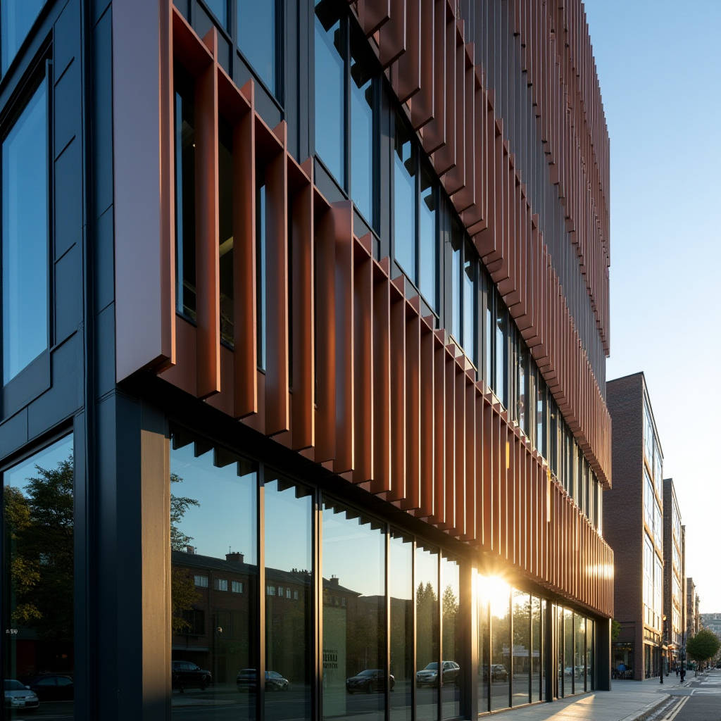
Aluminum facade fin systems have moved from niche architectural accents to mainstream building envelope components over the past decade. What drives this shift is not merely aesthetics — though the visual impact is undeniable — but a convergence of thermal performance demands, structural efficiency, and evolving building codes that penalize excessive solar gain. A well-specified aluminum facade fin does more than dress up a curtain wall. It intercepts direct radiation before it strikes the glazing, reduces cooling loads measurably, and introduces depth and shadow to surfaces that would otherwise read as flat. The engineering behind these extrusions, their attachment methods, finish durability, and wind behavior all demand careful attention. Getting any one of those variables wrong can turn a design feature into a maintenance liability or, worse, a safety hazard. This article unpacks the structural and thermal logic of aluminum facade fin systems, examines the alloy and finish choices that determine service life, and provides the kind of specification detail that procurement teams and facade engineers actually need when evaluating proposals.
What Actually Counts as an Aluminum Facade Fin
The term gets thrown around loosely in project specifications, but an aluminum facade fin is a distinct architectural element — a projecting linear profile fixed to the building envelope, oriented vertically or horizontally, and serving at least one of three functions: solar shading, visual modulation, or airflow direction. Unlike a simple trim piece or flashing, a facade fin carries depth. Typical projection ranges from 100mm to 600mm, though some parametric designs push well beyond 1000mm. The cross-section can be rectangular, tapered, elliptical, or twisted, and the profile is almost always extruded from 6063-T5 or 6063-T6 aluminum alloy — grades that balance extrudability with adequate mechanical strength.
What separates a genuine aluminum facade fin from decorative cladding strips is the engineering intent. Fins are structurally calculated elements. They must resist wind loads acting on their projected face, accommodate thermal movement without buckling, and transfer loads back to the primary structure through purpose-designed brackets. The attachment method — whether face-fixed to mullions, slotted into curtain wall transoms, or mounted on a separate sub-frame — determines how the system performs under cyclic loading. When a specification simply calls for "aluminum fins" without defining the alloy temper, bracket type, or thermal break strategy, the contractor ends up guessing. That guesswork has consequences.
Solar Shading Logic and Thermal Performance Data
The thermal argument for aluminum facade fins is straightforward: block direct solar radiation before it reaches the glass. What is less obvious is how dramatically fin geometry affects the outcome. A 300mm-deep vertical fin on a south-facing facade in Dubai performs differently than the same fin on a west-facing elevation in Melbourne. The key metric is the shading coefficient — the ratio of solar heat gain through a shaded versus unshaded window.
Consider a typical scenario: double low-E glazing with a solar heat gain coefficient (SHGC) of 0.35. Add a vertical aluminum facade fin with a projection-to-spacing ratio of 1:1.5, and the effective SHGC can drop to 0.18-0.22 depending on orientation. That translates to a 35-50% reduction in peak cooling demand for perimeter zones. The numbers matter because they directly affect HVAC sizing, energy code compliance, and — in jurisdictions like California under Title 24 or the EU under the Energy Performance of Buildings Directive — whether the project gets permitted at all.
Horizontal fins work differently. They shade high-angle sun effectively but leave low-angle morning and afternoon radiation largely unblocked. This is why many projects combine both orientations or specify egg-crate configurations where vertical and horizontal fins intersect. The trade-off is added weight, cost, and structural complexity. Each project demands its own solar geometry analysis; rules of thumb collapse quickly when the facade is curved or the site latitude exceeds 40 degrees.
Alloy Selection, Temper, and the Structural Reality
Not all aluminum is equal, and the difference between 6063-T5 and 6061-T6 matters when a fin projects 500mm from the facade and faces a 2.5 kPa wind load. The table below summarizes the key mechanical properties that facade engineers should reference during specification:
| Alloy & Temper | Yield Strength (MPa) | Tensile Strength (MPa) | Elongation (%) | Typical Facade Fin Application |
|---|---|---|---|---|
| 6063-T5 | 145 | 185 | 12 | Standard vertical fins, moderate wind zones |
| 6063-T6 | 170 | 205 | 10 | Deep projections, high-wind elevations |
| 6061-T6 | 240 | 290 | 10 | Structural fins, long spans, hurricane zones |
| 6082-T6 | 260 | 310 | 8 | Heavy-duty brackets, European market preference |
For most commercial aluminum facade fin applications, 6063-T6 hits the sweet spot. It extrudes well, accepts anodizing and PVDF coatings reliably, and provides enough strength for projections up to 400mm without requiring excessively thick walls. When fins exceed 600mm in depth or span more than 4 meters between supports, 6061-T6 becomes the safer choice despite its higher cost and slightly rougher surface finish after extrusion. The wall thickness of the extrusion itself typically ranges from 2.0mm to 3.5mm, with 2.5mm and 3.0mm being the most common for architectural-grade work. These are solid aluminum sections — not composite panels — and the thickness directly governs the section modulus and moment of inertia available to resist bending.
Wind Load Calculations and Bracket Design
Wind does not treat a facade fin gently. A fin projecting 400mm from the building face acts as a cantilevered beam subjected to wind pressure acting on its exposed surface area. The bending moment at the bracket connection is the product of wind pressure, fin depth, and the square of the span between supports. For a 400mm-deep fin spanning 3.5 meters between brackets in a 1.8 kPa wind zone, the bending moment at the support exceeds 1.1 kN·m. That demands a bracket assembly with sufficient embedment, edge distance, and corrosion resistance.
The bracket itself is typically fabricated from 5mm or 6mm thick aluminum plate — 5052-H32 or 6061-T6 — and designed with slotted holes to accommodate thermal movement. Stainless steel fasteners (A2-70 or A4-80 grade) are standard, and the interface between the aluminum fin and the bracket must include a thermal isolation pad to prevent galvanic corrosion and reduce thermal bridging. Where fins penetrate insulated spandrel zones, the thermal break detail becomes critical for meeting overall U-value targets. A poorly detailed bracket can create a linear thermal bridge that wipes out the energy savings the fin was supposed to deliver.
ASTM E1300 and AS/NZS 1170.2 provide the wind load frameworks most commonly referenced in specifications. The facade engineer should calculate the design wind pressure at each elevation, accounting for building height, exposure category, and local topography. Corner zones typically see 1.5 to 2.0 times the pressure of the field area, which means fin brackets at building corners often require closer spacing or stronger sections.
Finish Selection: Anodizing vs. PVDF vs. Powder Coating
The finish on an aluminum facade fin is not just about color. It determines the component's resistance to UV degradation, salt spray, industrial pollutants, and abrasion from wind-driven particles. Three primary finish types dominate the market, and each has distinct performance characteristics:
Anodizing builds an aluminum oxide layer electrochemically, typically 15-25 microns thick for architectural applications (AA-M12C12A31 Class I). The finish is integral to the metal surface, which means it cannot peel or delaminate. Anodized aluminum facade fins perform well in moderate climates but can exhibit color shift over time in high-UV environments. The color range is also limited — bronze, champagne, and natural silver tones dominate, with black anodizing being technically feasible but prone to fading.
PVDF (Polyvinylidene Fluoride) liquid coatings, applied at 30-40 microns dry film thickness, offer the widest color gamut and superior UV resistance. AAMA 2605-compliant PVDF systems use a three-coat or four-coat process with a primer, color coat, and clear topcoat. The fluoropolymer chemistry resists chalking and color fade for 20+ years in exposed conditions. For aluminum facade fin applications in coastal or high-pollution environments, PVDF is the default specification. The cost premium over anodizing runs 15-25%, but the long-term color stability justifies it for most commercial projects.
Powder coating — specifically AAMA 2604-compliant super-durable polyester powders — has gained ground in recent years. Applied at 60-80 microns, powder coatings provide excellent impact resistance and a uniform finish. However, their UV resistance falls short of PVDF, and gloss retention after 10 years of direct exposure can drop below 50%. For aluminum facade fin systems on premium projects, powder coating is generally reserved for sheltered applications or interior feature fins.
| Finish Type | Standard | Thickness | UV Resistance | Color Range | Relative Cost | Best-Suited Environment |
|---|---|---|---|---|---|---|
| Anodizing Class I | AAMA 611 | 15-25 µm | Moderate | Limited | 1.0x | Moderate climates, metallic tones |
| PVDF 3-Coat | AAMA 2605 | 30-40 µm | Excellent | Unlimited | 1.2-1.25x | Coastal, high-UV, premium commercial |
| Super-Durable Powder | AAMA 2604 | 60-80 µm | Good | Wide | 0.9-1.1x | Sheltered, interior, mid-range projects |
Thermal Movement and Tolerance Stacking
Aluminum expands at roughly 23.4 × 10⁻⁶ per degree Celsius. A 4-meter-long aluminum facade fin subjected to a 60°C temperature swing (from -10°C winter night to 50°C summer surface temperature) will expand approximately 5.6mm. If the fin is rigidly fixed at both ends, that expansion converts to compressive stress that can bow the profile or shear the fasteners. The solution is a combination of fixed and sliding connections: one bracket anchors the fin rigidly, while the remaining brackets incorporate slotted holes oriented parallel to the fin's longitudinal axis. The slot length must exceed the calculated thermal movement by a safety factor of at least 1.5.
Tolerance stacking is the other silent problem. The curtain wall structure has its own fabrication and installation tolerances — typically ±3mm per floor for mullion position. The fin brackets add another ±2mm. The fin extrusion itself has a straightness tolerance of ±1mm per meter. By the time the fin is installed, the cumulative deviation from the theoretical position can reach 8-10mm over a three-story span. This is visible to the naked eye, especially when fins are closely spaced. The fix is to design adjustment capability into the bracket system: vertical slotted holes for elevation adjustment, horizontal slots for alignment, and shim packs for angular correction. A good aluminum facade fin system accounts for these tolerances from the start rather than forcing the installer to field-modify components.
Installation Sequencing and the Cost of Getting It Wrong
Facade fin installation is deceptively simple on paper and brutally unforgiving on site. The sequence typically follows curtain wall glazing installation, which means the fins are among the last exterior elements to go up. At that stage, the project is often under schedule pressure, and the temptation to rush is real. Misaligned fins create a visual ripple effect that is impossible to unsee, and rectifying it requires dismantling and re-installing — at a labor cost that can exceed the original installation budget.
The practical approach that experienced contractors adopt is to install a reference line of fins first — typically the two end fins on each elevation — and then use tensioned wire lines or laser levels to align the intermediate fins. Bracket positions are verified before fin attachment, and each fin is checked for plumb and projection depth as it goes in. The process is slow, but the alternative is a facade that looks wavy under glancing light.
From a procurement standpoint, aluminum facade fin systems sourced from manufacturers with in-house extrusion and finishing capabilities — such as Futeng® — can reduce the coordination burden. When the same supplier controls the extrusion, machining, and coating processes, the dimensional consistency from fin to fin improves, and the finger-pointing that occurs when different vendors supply different components is eliminated. This is not about brand preference; it is about supply chain logic. Fewer handoffs mean fewer opportunities for error.
Parametric and Twisted Fin Geometries
The last five years have seen a surge in non-linear aluminum facade fin designs. Twisted fins — where the cross-section rotates along its length — create moiré effects and dynamic shadow patterns that change throughout the day. Parametrically varied fin depths produce undulating surfaces that read as organic rather than mechanical. These designs are computationally intensive to model and demanding to fabricate.
The fabrication challenge with twisted fins is that standard extrusion produces a constant cross-section. To achieve twist, the extruded profile must be post-formed — either by twisting the section while it is still hot from the extrusion press or by CNC machining the twist geometry from a solid billet. The hot-twist method is more economical for longer runs but limits the twist rate and angular range. CNC machining from solid aluminum plate offers unlimited geometric freedom but at a cost that can be 5-10 times higher than standard extruded fins. For most projects, the sweet spot is a hybrid approach: extruded straight sections for the bulk of the facade, with CNC-machined twisted elements used as accent features at entrances, corners, or transition zones.
The structural analysis of twisted fins is also more complex. A twisted section has varying stiffness along its length, and the wind load application point shifts as the geometry rotates. Finite element analysis (FEA) is typically required rather than hand calculations, and the bracket design must accommodate the torsional moment that the twist introduces. Projects using twisted aluminum facade fins should budget for additional engineering hours and expect a longer design development phase.
Fire Performance and Code Compliance
Aluminum melts at approximately 660°C, which is well below the temperatures reached in a fully developed building fire. This does not mean aluminum facade fins are inherently unsafe — it means they must be detailed so that their failure mode does not create additional hazards. The primary concerns are falling debris and the potential for fins to act as flame spread pathways if they are continuous across floor levels.
Most building codes require that external facade elements above a certain height be non-combustible or limited-combustible. Solid aluminum meets this requirement — it is classified as non-combustible under ASTM E136 and EN 13501-1 Class A1. However, the attachment system must also be considered. Brackets with polymeric thermal breaks or plastic shim packs can introduce combustible components into the assembly. The safer approach is to use stainless steel brackets with mineral-fiber thermal breaks where fire performance is a concern.
For high-rise residential projects in the UK (above 18m), the post-Grenfell regulatory environment demands rigorous documentation of every external wall component. An aluminum facade fin system specified for such projects should come with full test certifications, including EN 13501-1 classification reports and, where applicable, BS 8414 large-scale fire test data for the complete facade assembly. Procurement teams should request these documents during the tender phase, not after the contract is awarded.
Cost Drivers and Value Engineering Without Compromise
The cost of an aluminum facade fin system breaks down into four main buckets: material (extrusion + finish), brackets and fixings, engineering and shop drawings, and installation labor. Material cost is driven primarily by the weight of aluminum per linear meter — deeper fins with thicker walls cost more, and the relationship is roughly linear. Finish cost varies by type and color; custom PVDF colors carry a premium over standard RAL shades, and metallic or mica finishes add another layer of cost.
Where value engineering can be applied without compromising performance:
- Optimize fin spacing to reduce the total linear meter count while maintaining the required shading coefficient. A 10% increase in spacing can reduce material cost by 9% with minimal thermal performance impact.
- Standardize on a single fin profile across the project rather than specifying multiple custom extrusions. Die costs for custom profiles range from $2,000 to $5,000 each, and minimum order quantities apply.
- Use 6063-T6 instead of 6061-T6 where wind loads permit. The material cost difference is 8-12%.
- Specify PVDF only for exposed elevations and use anodizing or powder coating for sheltered or internal faces.
What should not be value-engineered: bracket thickness, fastener grade, thermal break details, and the number of fixing points per fin. These are safety-critical items, and cutting corners here creates liability that far outweighs the upfront savings.
Specification Checklist for Procurement Teams
When issuing an inquiry or tender for aluminum facade fin systems, the following information should be included to ensure comparable bids and technically sound proposals:
- Alloy and temper: Specify 6063-T6 as the baseline, with 6061-T6 for high-wind or long-span conditions.
- Finish type and standard: AAMA 2605 PVDF, AAMA 2604 powder, or AAMA 611 anodizing. State the color code and gloss level.
- Fin dimensions: Depth, width, wall thickness, and length. Include tolerances per applicable standards.
- Bracket system: Material grade, thermal break requirement, adjustment range, and fastener specification.
- Wind load criteria: Design pressure per elevation, including corner zone factors.
- Thermal movement accommodation: Required slot lengths and fixed/sliding point locations.
- Fire performance: Applicable standards and required test documentation.
- Shop drawings and calculations: Required submittals, including FEA reports for non-standard geometries.
Suppliers who cannot provide structural calculations stamped by a licensed engineer for the project jurisdiction should be disqualified. This is not a commodity product; the engineering is integral to the system.
Maintenance Realities Over the Service Life
An aluminum facade fin system is not maintenance-free, but it is low-maintenance when specified correctly. The primary maintenance activity is cleaning — accumulated dust and grime dull the finish and, in coastal environments, salt deposits can etch the surface if left unwashed. A six-monthly wash with mild detergent and water is sufficient for most locations. Pressure washing should be avoided on PVDF and powder-coated finishes because high-pressure spray can force water behind the coating at cut edges and fastener penetrations, initiating corrosion.
Anodized finishes require more care. The anodic layer is microporous, and contaminants can become trapped in the pores, causing staining that is difficult to remove. Proprietary anodizing cleaners exist, but the safest approach is frequent rinsing with clean water before deposits build up.
Bracket inspection should be part of the building's scheduled facade maintenance program. Stainless steel fasteners in aluminum can develop galvanic corrosion if the isolating washer or bush has degraded. Loose brackets produce audible rattling under wind load and visible misalignment. Catching these issues early avoids the cost of replacing entire fin sections.
The design life of a well-specified aluminum facade fin system is 30-50 years for the aluminum components and 20-30 years for the finish, depending on exposure conditions and maintenance diligence. This aligns with the typical lifecycle of curtain wall systems, which means the fins should not need replacement before the glazing does — a key consideration for life-cycle cost analysis.
ASTM International provides the governing standards for aluminum extrusions (ASTM B221) and architectural finishes (ASTM D4214). Refer to ASTM B221 for extrusion tolerances and AAMA 2605 for PVDF coating performance requirements. Wind load methodology is detailed in ASCE 7, and thermal performance calculations should reference ISO 15099 for fenestration systems.
Aluminum facade fin systems reward careful engineering. The decisions that matter — alloy selection, bracket design, finish specification, and tolerance planning — are made long before the first extrusion leaves the die. When those decisions are informed by real wind loads, real solar angles, and real installation constraints, the result is a facade element that performs thermally, holds its appearance for decades, and does not generate change orders. The alternative is a system that looks good in the rendering but creates problems on site. Facade engineers and procurement teams who understand the difference are the ones who sleep better at night.