Aluminium Sunshade Fin Wind Load Engineering What Facade Contractors Need to Specify
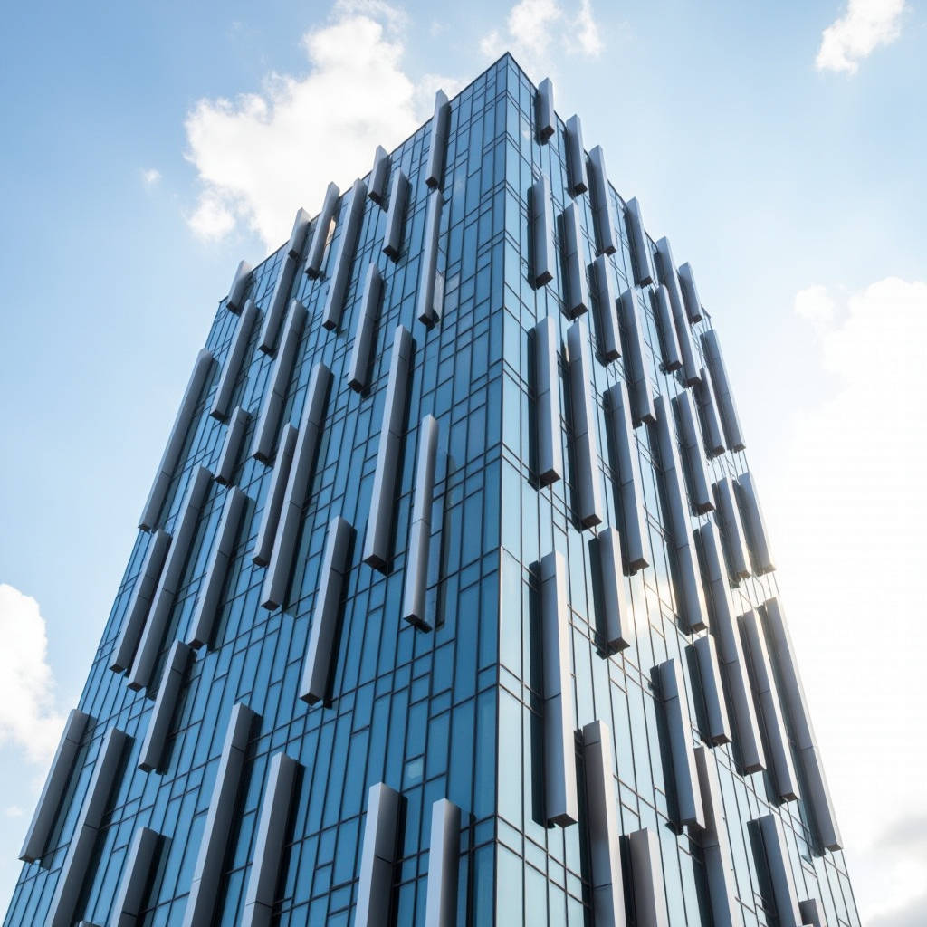
When specifying an Aluminium Sunshade Fin system for a high-rise facade, the conversation usually starts with aesthetics and energy performance. But the real headache for contractors and facade engineers comes later: wind. Unlike flat cladding panels, sunshade fins project outward from the building envelope, acting as small airfoils that catch and redirect wind pressure in ways that standard structural calculations often underestimate. A 300mm-deep fin spaced every 600mm across a 40-storey tower creates thousands of individual pressure points. Get the structural analysis wrong, and you are looking at fatigue cracks, fastener pull-out, or catastrophic detachment during a storm event. This article breaks down what actually matters when engineering Aluminium Sunshade Fin systems for wind resistance, from code requirements and pressure coefficients to material thickness selection and connection detailing.
Why Wind Loads Hit Sunshade Fins Harder Than Cladding
A flat aluminium panel on a rainscreen facade experiences wind pressure that is relatively predictable. The pressure distribution across the surface follows established patterns, and the load path transfers directly through the substructure to the primary frame. An Aluminium Sunshade Fin changes the game entirely. Because it projects perpendicular to the wall plane, wind strikes it from multiple angles simultaneously. The fin experiences positive pressure on the windward face, negative pressure (suction) on the leeward face, and vortex shedding along the edges. This combination creates torsional moments that try to twist the fin around its mounting axis. The longer and deeper the fin, the larger the moment arm and the higher the stress at the connection point.
Most building codes treat sunshade fins as "projections" or "appendages" and assign higher pressure coefficients than those used for wall surfaces. ASCE 7-22, for example, applies a net pressure coefficient that can be 1.5 to 2.5 times higher for projecting elements depending on their geometry and position on the building. Corner zones are particularly punishing. A fin located within the corner zone of a building (typically the outer 10% of the wall width) can see pressure coefficients spike by 30-50% compared to fins in the field of the wall. This is not a minor adjustment factor. It can mean the difference between a 2.0mm aluminium fin section that survives a 50-year storm and one that buckles at year three.
ASCE 7, EN 1991, and AS/NZS 1170: What the Codes Actually Require
Different jurisdictions use different standards, but the core principles overlap significantly. Under ASCE 7-22 (Chapter 30, C&C loads for components and cladding), sunshade fins fall under the provisions for "rooftop structures and equipment" or "wall projections" depending on their location. The effective wind area used for calculating design pressure is based on the tributary area of a single fin, which is often quite small. Small tributary areas mean higher design pressures because wind gusts affect small areas more intensely than large ones.
EN 1991-1-4 (Eurocode 1) takes a similar approach but uses different notation. The net pressure coefficient for free-standing walls, parapets, and projecting fins is covered in Section 7.4. For fins with an aspect ratio (length-to-depth) greater than 5, the code requires additional consideration of end effects and vortex-induced vibrations. This is where things get complicated. A slender 2000mm-long fin with only 150mm depth has an aspect ratio of 13.3, well into the zone where vortex shedding becomes a design concern. The Eurocode provides a simplified method using the force coefficient approach, but for complex geometries or critical structures, wind tunnel testing is recommended.
AS/NZS 1170.2 follows a similar framework to the Australian/New Zealand context. The standard provides specific pressure coefficients for "attachments to buildings" including sunshades. What catches many specifiers off guard is the requirement to consider both the ultimate limit state (ULS) and serviceability limit state (SLS). ULS ensures the fin does not collapse. SLS ensures it does not deflect so much that it looks alarming to occupants or causes the connections to work loose over time. A fin that visibly wobbles in moderate wind is a serviceability failure even if it never breaks.
A practical comparison of design wind pressures across these standards, assuming a 100m-tall building in Exposure Category C (open terrain), reveals significant variation:
| Standard | Zone | Design Pressure (kPa) | Pressure Coefficient | Notes |
|---|---|---|---|---|
| ASCE 7-22 | Field of Wall | 1.8 - 2.4 | 1.5 - 2.0 | Varies with effective wind area |
| ASCE 7-22 | Corner Zone | 2.8 - 3.6 | 2.2 - 3.0 | Higher suction on leeward face |
| EN 1991-1-4 | Field of Wall | 1.6 - 2.2 | 1.4 - 1.9 | Includes end-effect factor |
| EN 1991-1-4 | Corner Zone | 2.5 - 3.3 | 2.0 - 2.8 | Vortex shedding check required |
| AS/NZS 1170.2 | Field of Wall | 1.7 - 2.3 | 1.5 - 2.0 | ULS and SLS checks mandatory |
| AS/NZS 1170.2 | Corner Zone | 2.6 - 3.5 | 2.2 - 3.0 | Fatigue assessment for slender fins |
Material Thickness, Alloy Selection, and the Fatigue Question
Solid aluminium fins are typically fabricated from 6063-T5 or 6063-T6 extruded sections, or from 5052-H32 / 3003-H14 sheet when the fins are brake-formed from flat plate. The alloy choice matters for wind resistance. 6063-T6 offers higher yield strength (around 170 MPa) compared to 6063-T5 (around 145 MPa), which translates to roughly 15% more load capacity for the same section geometry. But T6 temper is slightly less ductile, which can be a concern for connections that rely on some plastic deformation to redistribute stress concentrations.
For brake-formed Aluminium Sunshade Fin sections made from solid sheet, 5052-H32 is the workhorse. With a yield strength of approximately 193 MPa and excellent corrosion resistance, it handles coastal environments well. The minimum thickness for a structural fin is rarely below 2.0mm. At 2.0mm, a 300mm-deep fin with a 1500mm span might work for moderate wind zones, but the deflection under SLS loading often pushes the required thickness to 2.5mm or 3.0mm. The difference in material cost between 2.0mm and 3.0mm 5052-H32 sheet is roughly 40-50%, so the engineering decision has real budget implications.
Fatigue is the silent killer of sunshade fin connections. Wind is not a static load. A fin on a tall building experiences millions of load cycles over its service life from gusting winds, vortex shedding, and pressure fluctuations. Each cycle is small, but the cumulative effect can initiate cracks at stress concentrations like bolt holes, weld toes, or sharp corners in the aluminium profile. AAMA 508 provides guidance on fatigue testing for sunshade systems, but it is not always mandated by project specifications. For buildings in hurricane-prone regions or locations with frequent high winds, specifying fatigue-resistant connection details is not optional. This means using oversized washers to distribute bearing stress, avoiding tapped holes in aluminium where the thread root acts as a stress riser, and ensuring that any welded connections are properly designed for cyclic loading.
Futeng® has supplied solid aluminium fin systems for projects in typhoon-prone Southeast Asian markets where wind loads regularly exceed 3.0 kPa design pressure. The engineering team there standardizes on 3.0mm 5052-H32 for fins deeper than 250mm in corner zones, with stainless steel through-bolts and continuous aluminium brackets rather than intermittent clips. That approach adds maybe 15% to the bracket cost but eliminates the weak-link problem that plagues cheaper clip-based systems.
Connection Design: Where Most Failures Start
The connection between the Aluminium Sunshade Fin and the building structure is the critical load path. There are three common approaches: face-fixed brackets that bolt through the fin into the substrate, slot-mounted systems where the fin slides onto a continuous aluminium rail, and end-plate connections where the fin is pre-assembled with welded or bolted end plates that attach to the structure.
Face-fixed brackets are the simplest and cheapest. A bracket is anchored to the concrete slab edge or steel subframe, and the fin is bolted to the bracket. The problem is that the bolt holes in the aluminium fin create stress concentrations exactly where the bending moment is highest. Under cyclic wind loading, the aluminium around the bolt hole can yield, the bolt loosens, and the connection develops play. Once there is play, the dynamic loads increase because the fin can now accelerate before hitting the limit of the slotted connection. This is a classic failure cascade. The fix is to use slotted holes with stainless steel bushings that distribute the bearing load, or to switch to a continuous rail system that spreads the load along the entire length of the fin.
Slot-mounted continuous rail systems are more expensive to fabricate but fundamentally better at handling wind. The fin's rear edge is profiled to slide into an extruded aluminium channel that is anchored to the structure. The channel provides continuous support, reducing the effective span of the fin and eliminating point-load stress concentrations. The trade-off is thermal movement. A 3000mm-long aluminium fin in a continuous channel will expand and contract with temperature changes. At a 50°C temperature swing, the thermal expansion is approximately 3.5mm. If the channel does not accommodate this movement, the fin buckles or the channel fasteners shear. The solution is to use a combination of fixed points and sliding connections, with PTFE or EPDM bearing pads at the sliding interfaces to prevent metal-to-metal galling.
End-plate connections are common for vertically oriented fins that span floor-to-floor. The fin is fabricated with welded aluminium end plates at top and bottom, which bolt to the slab edge or to a horizontal transom. The end plates carry the full bending moment from the fin into the structure. The weld between the fin and the end plate is the critical detail. A full-penetration weld with proper filler metal selection (5356 or 4043, depending on the base alloy) and post-weld heat treatment for 6063-T5 sections is the gold standard. Skipping the post-weld treatment can reduce the heat-affected zone strength by 30-40%, which is a significant hit to the fatigue life of the connection.
Vortex Shedding and Aeroelastic Effects
When wind flows past a projecting fin, vortices are shed alternately from each side of the fin. This creates a fluctuating pressure differential that applies a periodic cross-wind force. If the frequency of vortex shedding approaches the natural frequency of the fin, resonance occurs. The fin starts to oscillate, and the amplitude of oscillation can build rapidly. This is the same phenomenon that caused the Tacoma Narrows Bridge collapse, scaled down to architectural proportions.
The Strouhal number for a flat plate or airfoil-shaped fin is typically around 0.15 to 0.20. The vortex shedding frequency is calculated as f = St × V / D, where St is the Strouhal number, V is the wind velocity, and D is the fin depth. For a 200mm-deep fin in a 30 m/s wind (108 km/h, roughly a strong gale), the shedding frequency is around 22.5 to 30 Hz. If the fin's natural frequency falls within this range, resonance is a real risk.
Airfoil-shaped fins, like the extruded profiles offered by several manufacturers, have a significant advantage here. The streamlined shape reduces the intensity of vortex shedding compared to a flat plate. The pressure fluctuations are smaller, and the critical wind speed for resonance shifts higher. But even airfoil fins need a natural frequency check. The natural frequency depends on the fin's stiffness (a function of its moment of inertia and the aluminium's elastic modulus, approximately 69 GPa) and its mass. Adding mass reduces the natural frequency, which can move it away from the shedding frequency. This is why some very deep fins include internal stiffeners or are fabricated from thicker material than a pure strength calculation would suggest.
For projects where the architect insists on very slender, deep fins in a high-wind location, the responsible approach is to commission a wind tunnel test with a scaled model of the facade section. The American Society of Civil Engineers (ASCE) publishes guidelines for wind tunnel testing of building appendages. The cost is not trivial, typically $15,000 to $40,000 depending on the scope, but it is cheaper than replacing a failed facade system.
Corrosion, Coatings, and Long-Term Performance in Windy Coastal Zones
Wind and corrosion are a nasty combination. In coastal environments, wind-driven salt spray deposits chloride on the aluminium surface. If the coating system is compromised, pitting corrosion initiates at the breach point. Under cyclic wind stress, these pits act as crack initiation sites. The combination of corrosion and fatigue, known as corrosion fatigue, can reduce the fatigue life of an aluminium component by 50% or more compared to the same component in a dry environment.
The standard coating for architectural aluminium fins is PVDF (polyvinylidene fluoride) liquid coating, applied to meet AAMA 2605 specifications. This is a factory-applied system with a minimum total dry film thickness of 30 microns (1.2 mils), consisting of a chrome-based conversion coating, a corrosion-inhibitive primer, and a PVDF color coat. For coastal projects within 5km of saltwater, upgrading to a marine-grade PVDF system with a thicker primer layer and a minimum of 40 microns total DFT is standard practice. Some manufacturers also offer a clear anodized finish to meet AA-M12C22A31 specifications, which provides a hard, durable surface but is less effective at hiding scratches and handling damage than PVDF.
Powder coating is an alternative that has gained ground for sunshade fins. Qualicoat Class 2 or AAMA 2604 powder coatings offer good durability at a lower cost than liquid PVDF, but the film thickness is typically higher (60-80 microns) and the color range is more limited. The key advantage for wind resistance is that powder coating provides better edge coverage than liquid coatings. The edges of a fin are where wind-driven rain and salt spray hit first, and they are also the locations where coating defects are most common. A well-applied powder coat with good edge coverage can significantly extend the service life of fins in aggressive environments.
| Coating Type | Standard | Typical DFT (microns) | Coastal Suitability | Relative Cost | Edge Coverage |
|---|---|---|---|---|---|
| PVDF (Standard) | AAMA 2605 | 30-35 | Moderate (3-5km from coast) | 1.0x (baseline) | Fair |
| PVDF (Marine Grade) | AAMA 2605 | 40-50 | Excellent (<3km from coast) | 1.3-1.5x | Good |
| Powder Coating | AAMA 2604 / Qualicoat Class 2 | 60-80 | Good (3-5km from coast) | 0.7-0.9x | Very Good |
| Anodizing (Class I) | AA-M12C22A31 | 18-25 (oxide layer) | Good (with proper sealing) | 0.8-1.0x | Excellent |
| Super Durable Powder | AAMA 2605 / Qualicoat Class 3 | 60-80 | Excellent (<3km from coast) | 1.1-1.3x | Very Good |
Thermal Movement and Wind Load Interaction
Aluminium expands at roughly 23.4 × 10⁻⁶ per degree Celsius. A 3-metre fin subjected to a 60°C temperature swing from a cold winter night to direct summer sun expands by about 4.2mm. If the fin is rigidly fixed at both ends, this expansion generates compressive stress in the fin. The stress is calculated as σ = E × α × ΔT, where E is the elastic modulus (69,000 MPa), α is the coefficient of thermal expansion, and ΔT is the temperature change. For the 60°C swing, the thermal stress is approximately 97 MPa. That is a significant fraction of the yield strength of 6063-T5 aluminium (145 MPa).
Now add wind load to this. The combined stress from thermal expansion and wind-induced bending can exceed the allowable design stress if the connection detailing does not accommodate movement. This is why sliding connections are essential for long fins. The fixed point should be at the centre of the fin so that thermal expansion is symmetric, with sliding connections at both ends. The sliding connection detail must allow the calculated movement plus a safety factor of 1.5, and the bearing surfaces must be designed to prevent galling under repeated movement cycles.
The Aluminum Association publishes design guides that include detailed methods for calculating thermal stress and movement in aluminium structural components. Their recommendations for sliding connections include using stainless steel pins in slotted aluminium holes with PTFE washers, and ensuring that the slot length is at least 1.5 times the calculated movement range.
Specifying Wind Load Performance: What to Put in the Tender Documents
A well-written specification for an Aluminium Sunshade Fin system should include clear, verifiable wind load requirements. Vague language like "engineer shall design for wind loads per local code" invites disputes. The specification should state the design wind speed, the basic wind pressure, the pressure coefficients to be used for different zones of the building, and the allowable deflection limits under SLS loading.
For deflection, a common criterion is L/175 for the fin span under SLS wind load, where L is the span between supports. This is stricter than the L/60 or L/120 sometimes used for primary structural elements, because visible deflection of facade elements alarms building occupants. A fin that deflects 20mm under a gust may be structurally safe, but if the occupants on the 30th floor can see it moving, the facilities manager will be fielding complaints. Some specifications go further and require L/240 for fins in highly visible locations.
The specification should also require the supplier to submit calculations stamped by a licensed structural engineer, including the natural frequency analysis if the fins are slender. For projects in the US, the calculations should reference ASCE 7-22 and AAMA 508 for fatigue testing requirements. For European projects, EN 1991-1-4 and EN 1999-1-1 (design of aluminium structures) are the governing standards. The ISO 4354 standard provides a useful bridge for international projects where multiple codes may apply.
Practical Engineering Judgments for Common Scenarios
After years of reviewing sunshade fin submittals and investigating failures, a few patterns emerge that are worth codifying as practical rules of thumb. These are not substitutes for proper engineering analysis, but they help catch problems early in the design phase.
For horizontal fins (sunshades above windows), the governing load case is usually wind uplift acting on the top surface combined with the fin's self-weight. The fin acts as a cantilever from the wall, and the connection at the wall must resist both bending and torsion. The torsion comes from the fact that the wind uplift force acts at the centre of pressure of the fin, which is typically at the mid-depth of the fin, while the connection is at the rear edge. This offset creates a twisting moment. A 300mm-deep fin with a 150mm lever arm between the centre of pressure and the connection point sees a torsional moment equal to the wind force times 0.15m. Over many cycles, this torsion loosens bolted connections unless lock washers, thread-locking compound, or positive mechanical locking features are used.
For vertical fins, the governing case is often cross-wind loading combined with the fin's own dynamic response. Vertical fins are typically taller and more slender than horizontal fins, making them more susceptible to vortex-induced vibration. The connection at each floor level must transfer the wind load from the fin into the slab edge. If the fin spans multiple floors, the intermediate connections act as lateral supports that reduce the effective buckling length of the fin. A continuous vertical fin that is supported at every floor level is much stiffer than one that skips floors.
The bottom line for anyone specifying or installing Aluminium Sunshade Fin systems: wind is the controlling load case in almost every project. The structural design is not difficult, but it requires attention to details that are easy to overlook: corner-zone pressure coefficients, fatigue at connections, thermal movement accommodation, and vortex shedding checks for slender fins. A fin system that looks identical to a properly engineered one can fail within a few years if the connection detailing is wrong, the material is underspecified, or the coating is inadequate for the environment. The cost of getting it right is a small fraction of the cost of fixing it later.