Aluminum Sunshade Fin Structural Engineering Wind Load Brackets and Alloy Selection
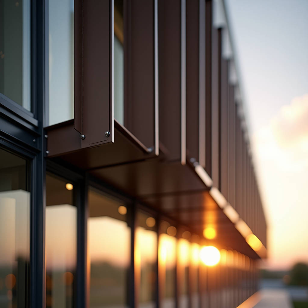
When specifying an Aluminum Sunshade Fin system for a high-rise facade, the structural engineer and the architect rarely speak the same language. One sees wind load tables, the other sees shadow lines. The gap between these two perspectives is where costly mistakes happen. An Aluminum Sunshade Fin is not just a decorative blade bolted onto a curtain wall. It is a cantilevered structural element that must resist cyclic wind pressures, thermal expansion, and decades of UV exposure while maintaining precise geometric alignment across thousands of square meters. This article focuses on the structural engineering dimension that procurement managers and facade contractors must understand before signing off on shop drawings: wind load calculations, bracket fatigue, and the material choices that determine whether a fin system survives 30 years or starts rattling in the first monsoon season.
Why Wind Load Governs Aluminum Sunshade Fin Design
Every Aluminum Sunshade Fin projecting from a building face acts as a small airfoil. Wind striking the blade generates both positive pressure on the windward side and suction on the leeward side. The combined effect produces a net force that the fin transfers to its mounting brackets, which in turn transfer it to the primary structure. Underestimating this force is the single most common cause of fin failure.
ASCE 7-22, the American standard for minimum design loads, classifies sunshade fins as "Components and Cladding" (C&C) rather than main wind force resisting systems. This distinction matters. C&C elements experience higher localized pressures than the building as a whole. A fin located near a building corner, where wind vortices create peak suction, can see pressures 2.5 to 3 times higher than a fin at mid-facade. The design professional must calculate wind pressures per Chapter 30 of ASCE 7-22, accounting for building height, exposure category, topographic effects, and the fin's specific location on the facade.
For a typical 100-meter-tall office tower in Exposure Category B (urban/suburban terrain), the velocity pressure qh at roof height might reach 1.2 kPa. Applying the appropriate external pressure coefficients (GCp) for a projecting horizontal surface, a single Aluminum Sunshade Fin measuring 300 mm deep by 3,000 mm long could experience a design wind load exceeding 2.5 kN. That is not a trivial number for a cantilevered aluminum extrusion.
Pressure Coefficient Nuances That Shop Drawings Often Miss
Many fabricators apply a single conservative GCp value across all fins on a project. This simplifies fabrication but over-engineers some fins and dangerously under-engineers others. The correct approach, per ASCE 7-22 Figure 30.3-2B, requires different pressure coefficients for corner zones (Zone 5), edge strips, and interior areas. Corner fins may require bracket spacing reduced by 30-40% compared to interior fins. A rigorous shop drawing package will color-code fin locations by wind zone and specify the corresponding bracket type and spacing for each zone.
Wind tunnel testing adds another layer of refinement. For complex geometries, especially buildings with curved facades or irregular massing, the code-prescribed coefficients may not capture the actual pressure distribution. A wind tunnel study conducted per ASCE 49-21 can reduce design wind loads by 15-25% compared to code values, translating directly into thinner fin sections or wider bracket spacing. The cost of the wind tunnel study often pays for itself in material savings on projects exceeding 5,000 square meters of fin coverage.
Bracket Design: The Overlooked Failure Point
An Aluminum Sunshade Fin rarely fails in the blade itself. The aluminum extrusion, properly sized, handles bending stresses comfortably. The failure locus is almost always the bracket-to-fin connection or the bracket-to-structure anchor. This is where fatigue, galvanic corrosion, and installation tolerances converge.
Brackets for aluminum sunshade fins must accommodate three distinct movement types: vertical deflection under self-weight and wind, horizontal rotation from thermal expansion, and longitudinal movement along the fin axis. A rigid bracket that locks all three degrees of freedom will eventually crack either the fin, the bracket, or the anchor bolt. The industry standard solution is a two-part bracket assembly: a fixed anchor bracket at one end of the fin span and a sliding bracket at the other, allowing ±5 mm of axial movement.
Thermal movement calculations are straightforward but frequently omitted from fabrication drawings. Aluminum expands at approximately 0.024 mm per meter per degree Celsius. A 4-meter-long fin subjected to a 60°C temperature swing (from -10°C winter night to 50°C summer afternoon on a dark-colored PVDF coating) will expand by roughly 5.8 mm. If both ends are rigidly fixed, this expansion generates compressive stress in the fin. For a 6063-T6 aluminum extrusion with a cross-sectional area of 1,500 mm², the resulting thermal stress can reach 40 MPa, consuming a significant portion of the material's allowable stress before any wind load is applied.
Galvanic Corrosion at the Bracket Interface
Where the aluminum fin meets a stainless steel bracket, a galvanic cell forms in the presence of moisture. Aluminum is anodic to stainless steel; it will sacrifice itself. The severity depends on the environment. In coastal locations with airborne chlorides, the corrosion rate accelerates dramatically. The standard mitigation is a physical barrier: a 0.5 mm thick EPDM or neoprene isolation pad between the aluminum fin and the stainless steel bracket. Some specifications also require the stainless steel fasteners to be coated with a zinc-aluminum flake coating for additional protection.
The AAMA 2604 and AAMA 2605 standards for organic coatings on aluminum extrusions address corrosion resistance indirectly through accelerated weathering tests, but they do not cover galvanic isolation. That responsibility falls on the specifier. A well-written specification will explicitly call out isolation pads, specify the pad material and thickness, and require the fabricator to submit galvanic corrosion mitigation details as part of the shop drawing package.
Material Selection: Extrusion Alloys and Temper Designations
The overwhelming majority of Aluminum Sunshade Fin profiles are extruded from 6063-T6 or 6061-T6 alloys. The choice between them involves a trade-off between extrudability, surface finish quality, and mechanical properties.
6063-T6 offers excellent extrudability, allowing complex hollow profiles with thin walls down to 1.5 mm. Its surface finish after anodizing or PVDF coating is consistently smooth, making it the preferred choice for visible architectural elements. The yield strength of 6063-T6 is 170 MPa, and its ultimate tensile strength is 205 MPa. For most sunshade fin applications with spans under 3 meters and depths under 400 mm, 6063-T6 provides adequate strength with a comfortable safety factor.
6061-T6 provides higher strength (yield: 240 MPa, ultimate: 260 MPa) but at the cost of reduced extrudability. Thin-walled complex shapes are harder to achieve, and surface finish quality may be slightly inferior. 6061-T6 is typically reserved for long-span fins exceeding 4 meters or for projects in high-wind regions where 6063-T6 would require uneconomically thick sections.
A less common but noteworthy option is 6063-T5, which has a lower yield strength (110 MPa) and is sometimes used for purely decorative fins that carry no significant structural load. The specifier must verify that the fabricator has not substituted T5 for T6 without approval, as the visual difference is nonexistent but the structural difference is substantial.
| Property | 6063-T5 | 6063-T6 | 6061-T6 |
|---|---|---|---|
| Yield Strength (MPa) | 110 | 170 | 240 |
| Ultimate Tensile Strength (MPa) | 150 | 205 | 260 |
| Elongation (%) | 12 | 10 | 10 |
| Extrudability | Excellent | Very Good | Good |
| Surface Finish Quality | Excellent | Excellent | Very Good |
| Typical Application | Decorative fins, low-load | Standard sunshade fins | Long-span, high-wind |
| Approximate Cost Ratio | 0.90 | 1.00 | 1.15 |
PVDF Coating Specifications for Exterior Fins
An Aluminum Sunshade Fin exposed to 30 years of UV radiation, acid rain, and airborne pollutants needs a coating system that does not chalk, fade, or delaminate. The industry benchmark is AAMA 2605, which governs high-performance organic coatings on aluminum extrusions and panels. AAMA 2605 requires a minimum of 70% PVDF resin content by weight in the color coat, a minimum total dry film thickness of 30 microns for a two-coat system, and passing results after 4,000 hours of accelerated weathering in a QUV or xenon arc apparatus.
The two-coat system consists of a primer layer (typically 5-8 microns) and a color coat (20-25 microns). For coastal or highly polluted environments, a three-coat system adds a clear topcoat that provides additional UV screening and chemical resistance. The clear coat adds approximately 5-8 microns to the total film thickness and increases cost by roughly 15-20%.
Color choice affects long-term performance. Dark colors absorb more solar radiation, raising the surface temperature of the fin and accelerating coating degradation. A black fin in direct sunlight can reach 80°C, while a white fin under the same conditions might stay below 50°C. The PVDF resin itself is stable at these temperatures, but the pigments and the primer-to-substrate bond are stressed. For dark-colored fins, specifying a three-coat system with a ceramic pigment in the color coat is a prudent investment.
Quality Control Checks During Fabrication
Procurement managers should require the coating applicator to provide a batch-specific quality control report for each fin shipment. The report should include dry film thickness measurements per ASTM D7091, gloss readings per ASTM D523, color difference (ΔE) per ASTM D2244, and adhesion test results per ASTM D3359 (cross-hatch method). A ΔE value below 1.0 is generally considered imperceptible to the human eye, but for adjacent fins on a single facade, even a ΔE of 0.5 can be noticeable under certain lighting conditions. Tight specifications limit ΔE to 0.5 or less for fins installed on the same elevation.
Futeng® has supplied PVDF-coated Aluminum Sunshade Fin systems for projects across Southeast Asia and the Middle East, where the combination of high UV exposure and saline atmospheres pushes coating performance to its limits. The key lesson from these projects is that coating quality correlates directly with pretreatment quality. A seven-stage pretreatment process (degrease, rinse, alkaline etch, rinse, deoxidize, rinse, chromate conversion coating) produces a surface that bonds tenaciously to the PVDF primer. Skipping or shortening any stage saves minutes but costs years of service life.
Deflection Limits and Serviceability Criteria
Strength governs safety, but deflection governs perception. A fin that is structurally adequate but visibly deflecting under wind load will generate complaints from building occupants and passersby, even if it poses no risk of collapse. The industry standard for Aluminum Sunshade Fin deflection is L/175 for wind load, where L is the span length. For a 3-meter span, this allows a maximum deflection of 17 mm at the tip. Some specifications tighten this to L/240 for fins at eye level or in prominent locations.
More critical than the absolute deflection is the relative deflection between adjacent fins. If one fin deflects 15 mm and its neighbor deflects 5 mm, the 10 mm differential creates a visible misalignment that reads as a quality defect. The solution is to design all fins in a given wind zone to the same stiffness, not just the same strength. This means specifying a minimum moment of inertia (I) for the extrusion profile rather than simply a minimum section modulus (S). A fabricator who optimizes purely for strength may deliver fins that pass the stress check but exhibit inconsistent deflection behavior.
Installation Tolerances and Field Adjustments
Even the most precisely fabricated Aluminum Sunshade Fin will look sloppy if installed with poor alignment. The AAMA TIR-A11 provides recommended installation tolerances for metal curtain wall components, including sunshade fins. Key tolerances include: ±3 mm for fin-to-fin spacing, ±2 mm for fin projection from the facade plane, and ±1.5 mm per meter for fin straightness.
These tolerances are achievable only if the supporting structure is within tolerance. The contractor must verify that the anchor channel or embed plate positions are within ±5 mm of the design location before fin installation begins. A common sequence error is installing curtain wall mullions, then discovering that the embedded anchor points for the fins are 10 mm out of position. The fix involves slotted brackets, shim packs, or, in the worst case, post-installed anchors with epoxy adhesive. Each of these fixes adds cost and time, and each introduces a potential long-term durability concern.
Field drilling of aluminum fins should be avoided whenever possible. If field modifications are necessary, the contractor must apply a touch-up coating to any exposed aluminum surfaces. A two-part epoxy touch-up paint is acceptable for small areas, but the color match must be verified against the factory-applied PVDF coating. For fins with a metallic or mica finish, achieving an acceptable touch-up match is notoriously difficult, and the specifier should consider requiring a replacement fin for any damage exceeding 500 mm².
Fire Performance and Building Code Compliance
Aluminum sunshade fins are non-combustible, which simplifies compliance with the exterior wall provisions of the International Building Code (IBC). However, fins that project more than 100 mm from the facade may affect the fire spread path between floors. The IBC requires vertical separation between floors to prevent flame propagation up the exterior wall. A deep horizontal fin can act as a flame deflector or, conversely, as a flame spread pathway depending on its geometry and the presence of firestopping at the slab edge.
The project's fire protection engineer should review the fin geometry in the context of the overall facade fire strategy. In some jurisdictions, fins that project more than 300 mm may require a fire propagation analysis per NFPA 285, which tests the entire exterior wall assembly including the fins. This is a full-scale test that evaluates flame spread over the exterior surface and through the wall cavity. Specifying fins made from solid aluminum with zero combustible content simplifies the analysis but does not eliminate the need for assembly-level testing if the backup wall contains combustible insulation or water-resistive barriers.
Cost Drivers and Value Engineering
The cost of an Aluminum Sunshade Fin system breaks down into material, fabrication, coating, brackets, and installation. Material cost is driven by the weight per linear meter of the extrusion, which is a function of the cross-sectional area. Fabrication cost is driven by the number of cuts, miters, and end-cap details. Coating cost is driven by the number of coats and the color complexity. Bracket cost is driven by the number of brackets per fin and whether they are standard or custom-designed. Installation cost is driven by access complexity, the number of anchor points, and the alignment tolerance required.
Value engineering efforts should focus on reducing the number of unique fin profiles and bracket types, not on reducing material thickness. A project with 15 different fin profiles may offer architectural variety, but it multiplies extrusion die costs, inventory complexity, and installation errors. Reducing the profile count to 5 or 6 while maintaining the same visual rhythm can cut total system cost by 10-15% without compromising the design intent.
Bracket standardization offers similar savings. A custom cast aluminum bracket might cost $15-25 per unit in quantities of 500, while a standardized extruded bracket might cost $5-8. For a project with 2,000 brackets, the difference is $20,000 to $34,000. The architect rarely sees the brackets, so this is an area where procurement managers can push back without affecting the visual outcome.
Specifying an Aluminum Sunshade Fin System: A Practical Checklist
Based on the structural, material, and installation considerations discussed above, the following checklist provides a framework for a robust specification:
- Define the wind load criteria. Reference ASCE 7-22, specify the basic wind speed, exposure category, and whether wind tunnel data is available. Require the fabricator to submit wind load calculations for corner, edge, and interior zones separately.
- Specify the aluminum alloy and temper. 6063-T6 for standard applications, 6061-T6 for long spans or high-wind zones. Prohibit substitution without written approval.
- Define the coating system. AAMA 2605 compliant, 70% PVDF resin minimum, two-coat or three-coat as appropriate for the environment. Require batch-specific QC reports.
- Detail the bracket system. Specify fixed and sliding brackets, isolation pads, fastener material and coating, and bracket spacing by wind zone.
- Set deflection limits. L/175 minimum, L/240 for prominent locations. Require the fabricator to provide deflection calculations for each fin type.
- Establish installation tolerances. Reference AAMA TIR-A11. Require a pre-installation survey of anchor positions.
- Address fire performance. Confirm whether NFPA 285 testing is required. Document the non-combustible nature of the aluminum fins.
- Require a mock-up. A full-scale mock-up of at least two bays, including the curtain wall, fins, and all bracket types, should be erected and tested before production begins.
An Aluminum Sunshade Fin system that follows these guidelines will deliver decades of reliable performance. The investment in proper engineering, material selection, and quality control during fabrication pays back through reduced maintenance, fewer warranty claims, and a facade that maintains its visual integrity long after the construction hoarding comes down. For procurement managers navigating the global supply chain, the key is to engage fabricators who understand the structural engineering behind the extrusion, not just the aesthetics. The best fin is the one that performs invisibly, doing its job of shading and shaping the building without drawing attention to itself through rattles, corrosion, or misalignment.
ASCE 7-22 Minimum Design Loads for Buildings provides the authoritative framework for wind load determination on building components and cladding. AAMA 2605-20 defines the performance requirements for high-performance organic coatings on aluminum extrusions, including the 70% PVDF resin content minimum and 4,000-hour weathering requirement. ASTM D3359 specifies the cross-hatch adhesion test method used to verify coating bond strength. NFPA 285 governs the fire propagation characteristics of exterior wall assemblies containing combustible components. AAMA TIR-A11 provides recommended installation tolerances for metal curtain wall components including sunshade devices.