Aluminium Sun Louver Engineering Wind Load Brackets and Coating Durability for Facade Systems
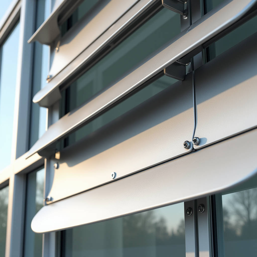
When specifying an Aluminium Sun Louver system for a commercial facade, the conversation rarely stays on shading alone. Within two or three rounds of technical submittals, the discussion shifts to structural load transfer, thermal bridging at bracket penetrations, and whether the specified powder coat will still look uniform after five years of coastal exposure. These are the questions that separate a facade element that performs for two decades from one that generates punch lists within the first 18 months. This article walks through the engineering decisions that determine long-term performance of aluminium sun louver installations, with a focus on wind load behavior, coating durability across climate zones, and the bracket-to-structure interface that causes most warranty claims.
Why Aluminium Sun Louver Geometry Dictates Structural Strategy
A sun louver is not a cladding panel. It projects outward from the building envelope, which means every blade acts as a cantilevered airfoil subject to both positive and negative wind pressure. The aerodynamic profile matters. An elliptical aerofoil blade with a 300mm chord will experience roughly 40% lower net pressure coefficients than a flat rectangular blade of the same projection, based on wind tunnel data referenced in AS/NZS 1170.2. This is not a marginal difference. On a 40-story tower in a typhoon-prone region, the cumulative uplift on flat-profile louvers can exceed the pull-out capacity of standard M10 stainless steel anchors if the bracket spacing was calculated using aerofoil assumptions.
The blade width-to-thickness ratio also governs torsional stiffness. A 250mm-wide extruded aluminium blade with a wall thickness of 2.5mm will begin to twist visibly under a sustained 1.8 kPa wind load if the span between brackets exceeds 1,400mm. The twist is not just cosmetic. Once a blade rotates more than 3 degrees under load, the intended shading angle shifts, and the solar control performance degrades. Engineers who treat louver deflection criteria the same as facade panel deflection criteria (typically L/60 or L/90) miss this point. For Aluminium Sun Louver blades, a torsional rotation limit of 2 degrees at design wind load is a more useful benchmark.
Wind Load Calculations: The Numbers Behind Bracket Spacing
Every Aluminium Sun Louver shop drawing should include a wind load schedule that correlates blade span, bracket spacing, and the resulting stress ratio in the aluminium extrusion. The calculation chain works like this:
First, determine the design wind pressure for the specific building zone. Corner zones on high-rise structures can see pressures 2.5 to 3 times higher than the field zone, per ASCE 7-22. A louver located within 1.5 meters of a building corner on a 100-meter-tall tower in Exposure Category C might need to resist 3.8 kPa, while the same louver in the field zone sees only 1.6 kPa. This means the bracket spacing that works for 80% of the facade will fail at the corners unless the shop drawings differentiate zones.
Second, the blade profile's section modulus dictates bending capacity. A 6063-T6 aluminium aerofoil extrusion with a 150mm chord and 2.0mm wall typically has a section modulus (Z) in the range of 4.5 to 6.2 cm³ depending on internal rib geometry. At a 1,200mm span with 3.0 kPa uniform load, the bending moment reaches approximately 0.54 kN·m, and the resulting stress hits 87-120 MPa. Since 6063-T6 has a yield strength of 170 MPa (per ASTM B221), the stress ratio is 0.51 to 0.71. That is acceptable for static loads, but fatigue becomes a concern when wind-induced oscillation cycles exceed 10⁴ over the service life.
Third, the bracket itself needs checking. A typical aluminium louver bracket fabricated from 6mm 6061-T6 plate with two M8 stainless steel bolts into a concrete embedment has a pull-out capacity of roughly 4.2 kN per anchor in 30 MPa concrete. Under 3.8 kPa corner-zone pressure on a louver with a tributary area of 0.36 m² per bracket, the tension demand is 1.37 kN. The anchor utilization ratio is 0.33, which is comfortable. But if the same bracket is installed into a hollow-core precast panel with only 40mm of edge distance, the concrete breakout capacity drops to around 1.8 kN, and the utilization ratio jumps to 0.76. This is the kind of detail that separates a properly engineered submittal from one that gets rejected in peer review.
| Blade Span (mm) | Bracket Spacing (mm) | Design Pressure (kPa) | Stress Ratio (6063-T6) | Max Deflection (mm) | Torsional Rotation (°) |
|---|---|---|---|---|---|
| 1,000 | 1,200 | 2.0 | 0.38 | 4.2 | 1.2 |
| 1,200 | 1,200 | 2.0 | 0.51 | 7.1 | 1.8 |
| 1,200 | 1,000 | 3.0 | 0.48 | 5.8 | 1.5 |
| 1,500 | 1,200 | 2.0 | 0.72 | 13.6 | 3.1 |
| 1,500 | 900 | 3.5 | 0.65 | 9.4 | 2.2 |
This table illustrates why span-to-spacing ratios matter more than either number alone. A 1,500mm span at 1,200mm spacing passes stress checks at 2.0 kPa but exceeds torsional limits. The same span at 900mm spacing handles 3.5 kPa with acceptable rotation. Specifying the right combination requires knowing the project's wind zone map, not just the average pressure.
Coating Selection: PVDF, Powder, and the Coastal Exposure Reality
The coating on an Aluminium Sun Louver does more than provide color. It is the only barrier between the 6063-T6 aluminium substrate and the atmosphere. In inland urban environments, a high-quality polyester powder coating meeting AAMA 2604 will deliver 10-15 years of color stability and chalk resistance. But within 3 kilometers of a coastline, or in industrial zones with SO₂ levels above 30 μg/m³, the specification needs to shift to PVDF (polyvinylidene fluoride) coatings meeting AAMA 2605.
The difference is measurable. AAMA 2605 requires a minimum of 10 years of South Florida exposure testing with delta-E color change below 5.0 and chalk rating no worse than 8. AAMA 2604 only requires 5 years with delta-E below 5.0. In practice, a dark bronze PVDF coating on an aluminium sun louver in Dubai will show delta-E of 2.8 after 7 years, while a polyester powder of the same color will exceed delta-E 6.0 in the same period. The cost premium for PVDF is typically 18-25% per square meter of louver surface area, but the alternative is recoating or replacement at year 12, which costs 3-5 times the original coating cost when access equipment and business interruption are factored in.
For projects in the Middle East and Southeast Asia, a three-coat PVDF system with a 35-40 micron total dry film thickness is the baseline. The primer layer (5-10 microns) provides adhesion and corrosion resistance. The color coat (20-25 microns) carries the pigment and the bulk of UV-blocking function. The clear topcoat (10-15 microns) adds gloss retention and additional UV screening. Some manufacturers offer a four-coat system with a separate barrier primer for marine environments, which adds roughly 8-12% to the coating cost but doubles the salt-spray resistance per ASTM B117 from 3,000 hours to over 6,000 hours.
Thermal Performance: The Gap Between Shading Coefficient and Reality
An Aluminium Sun Louver system is often specified with a target shading coefficient. A horizontal aerofoil louver array with 300mm blade spacing and a 45-degree blade angle can achieve a shading coefficient of 0.25-0.35 on the south-facing facade (in the northern hemisphere), meaning it blocks 65-75% of direct solar radiation. But the shading coefficient is a geometric property. It does not account for the thermal bridge created by the aluminium bracket that penetrates the insulation layer and bolts directly to the structural slab or steel subframe.
Each bracket creates a point thermal bridge with a linear thermal transmittance (psi-value) typically between 0.15 and 0.45 W/(m·K) depending on the bracket geometry and whether a thermal break pad is installed. On a facade with brackets at 1,200mm centers horizontally and every floor vertically (3,600mm spacing), the total bracket thermal bridge contribution can add 0.08-0.15 W/(m²·K) to the overall wall U-value. For a curtain wall targeting U-0.35 W/(m²·K) under ASHRAE 90.1, that 0.10 W/(m²·K) increment is a 29% penalty. Thermal break pads made from 6mm thick polyamide or fiberglass-reinforced phenolic material can reduce the psi-value to 0.06-0.12 W/(m·K), bringing the penalty down to 0.03-0.06 W/(m²·K).
The blade itself also contributes to secondary heat gain. A dark-colored aluminium louver blade in direct sun can reach a surface temperature of 75-80°C. If the blade is mounted within 150mm of the vision glass, the re-radiated heat raises the outer glass surface temperature by 3-5°C, which increases the cooling load on the perimeter zone. A gap of 250mm or more between the louver trailing edge and the glass line reduces this effect to under 1°C. This is a coordination detail that should appear on the facade section drawings, but often does not.
Installation Sequence and the Cost of Rework
The bracket installation sequence for Aluminium Sun Louver systems directly affects the final alignment tolerance. The most common approach is to install brackets onto the structure first, then attach blades, then adjust. But if the structural substrate has a tolerance of ±15mm over a 3-meter grid (which is typical for cast-in-place concrete), and the louver system requires a ±3mm alignment for visual consistency, the adjustment mechanism in the bracket must accommodate 12mm of differential movement.
Slotted connections in the bracket base plate can absorb ±8mm in the vertical plane. Horizontal adjustment of ±5mm is achievable with oversized holes and serrated washer plates. But the rotational adjustment around the horizontal axis perpendicular to the facade is the one that gets overlooked. If the bracket is welded to an embedded plate that is 2 degrees off vertical, a 250mm-deep louver blade will be 8.7mm out of plane at its tip. Correcting this requires a spherical washer assembly at the blade-to-bracket connection, which adds roughly $4-6 per connection point. On a project with 3,000 brackets, that is $12,000-18,000 in hardware that was probably not in the original budget.
For projects where Futeng® supplies the aluminium louver extrusions and mounting hardware, the submittal package typically includes a tolerance stack-up analysis that maps the adjustment range of each connection point against the expected structural deviations. This document alone can prevent 60-70% of the alignment disputes that arise during installation.
Material Grade Selection: 6063-T5 vs 6063-T6 vs 6061-T6
Most aluminium sun louver blades are extruded from 6063 alloy because it extrudes well with good surface finish. The temper choice matters. 6063-T5 has a minimum yield strength of 110 MPa and ultimate tensile strength of 150 MPa. 6063-T6 raises those to 170 MPa and 205 MPa respectively. The T6 temper costs roughly 8-12% more per kilogram of extrusion but provides 55% higher yield strength. For louver blades with spans under 1,200mm and design pressures under 2.0 kPa, T5 is adequate. For longer spans, corner zones, or typhoon/hurricane regions, T6 is the correct specification.
Brackets are a different story. 6061-T6 is the standard for structural aluminium components, with a yield strength of 240 MPa. Some fabricators use 6063-T6 for brackets to simplify material procurement, but 6063-T6 brackets need to be roughly 15-20% thicker than 6061-T6 equivalents to achieve the same load capacity. The weight penalty offsets the material cost saving, and the thicker bracket may not fit within the blade profile envelope. The better approach is to use 6061-T6 for all load-bearing brackets and 6063-T6 for the blades, accepting the dual-material inventory.
Corrosion: Galvanic Couples and the Stainless Steel Fastener Question
Aluminium and stainless steel are close on the galvanic series, but not close enough to ignore. In the presence of an electrolyte (rainwater, condensation, coastal spray), a galvanic couple forms between the aluminium louver blade and the stainless steel bolt. The aluminium, being more anodic, corrodes preferentially. The rate depends on the surface area ratio. A large aluminium surface area coupled to a small stainless steel fastener area produces slow, manageable corrosion. But if the fastener is in a crevice where water can pool and the area ratio is inverted (small aluminium area, large stainless area), pitting corrosion can progress at 0.1-0.3mm per year in marine environments.
The mitigation is straightforward: use nylon or EPDM isolation washers between the stainless steel bolt head and the aluminium surface, and apply a zinc-rich primer or Dacromet coating to the fastener threads. For projects within 500 meters of a coastline, specify 316 stainless steel fasteners rather than 304. The molybdenum content in 316 (2-3%) provides significantly better resistance to chloride-induced pitting. The cost difference is roughly $0.15-0.30 per fastener, which on a large project might total $5,000-10,000 — a small premium compared to the cost of replacing corroded fasteners from a swing stage 15 years later.
Fire Performance: The Often-Overlooked Requirement
Aluminium melts at approximately 660°C. In a facade fire, external aluminium sun louvers can soften, deform, and detach. Building codes in many jurisdictions, including the UK (Approved Document B) and Australia (NCC Volume 1), require external attachments above certain heights or near boundary lines to meet non-combustibility requirements or limited combustibility criteria. Aluminium itself is classified as A1 (non-combustible) per EN 13501-1, but the coating system, gaskets, and thermal break materials may not be.
A PVDF coating with a dry film thickness under 50 microns applied to solid aluminium is generally considered to have negligible contribution to fire load. But EPDM gaskets and polyamide thermal breaks are combustible. The total combustible content of a louver system with thermal breaks and gaskets is typically 3-8 MJ/m², which may exceed the 3 MJ/m² threshold in some codes. Specifying silicone-based gaskets and fiberglass-reinforced phenolic thermal breaks can reduce the combustible content to under 2 MJ/m². This is a specification detail that facade engineers should verify during the technical submittal stage, not after the fire engineer's review.
Acoustic Considerations: Rain Noise and Wind Whistle
An Aluminium Sun Louver system can generate noise in two ways: impact noise from rain striking the blades, and aerodynamic whistle from wind passing through the blade array. Rain noise is primarily a function of blade stiffness and damping. A hollow aluminium extrusion without internal damping will produce a sound pressure level of 65-70 dB(A) at 1 meter under heavy rain (50mm/hour). Filling the blade cavity with a closed-cell polyethylene foam insert can reduce this by 8-12 dB(A), bringing it into the 53-60 dB(A) range that is less intrusive for building occupants.
Wind whistle occurs when the Strouhal number of the airflow around the blade profile falls between 0.2 and 0.4, generating vortex shedding at audible frequencies. For a 150mm chord aerofoil blade in a 15 m/s wind (54 km/h), the vortex shedding frequency is approximately 20-30 Hz, which is at the low end of human hearing. Narrower blades and higher wind speeds push the frequency higher, into the 50-200 Hz range where the ear is more sensitive. The solution is to specify blade profiles with a blunt trailing edge (0.5-1.0mm radius) rather than a sharp edge, which disrupts the regular vortex shedding pattern. This is a small geometric change with no cost impact, but it needs to be in the extrusion die design from the start.
Bringing the Specification Together
The Aluminium Sun Louver specification that survives a decade of service without generating complaints is the one that treats wind load, coating, thermal bridging, corrosion, fire, and acoustics as interconnected requirements rather than separate checklist items. A louver system that passes structural checks but uses the wrong coating for the site's distance from the coast will fail cosmetically. A system with the right coating and structural design but no thermal break pads will penalize the building's energy performance. The engineering is in the intersections.
For project teams preparing technical specifications, the key documents to reference include AAMA 2605-22 for coating performance, ASTM B221 for extrusion tolerances and mechanical properties, ASCE 7-22 for wind load determination, and ISO 9223 for atmospheric corrosivity classification. The shop drawing review should verify bracket spacing against the project's wind zone map, not just the average pressure. The coating submittal should include AAMA 2605 test reports from an accredited laboratory, not just the manufacturer's data sheet. And the thermal analysis should include the bracket point thermal bridges, not just the blade shading coefficient.
The difference between a louver system that performs and one that disappoints is rarely the aluminium itself. It is the engineering rigor applied to the connections, the coatings, and the environmental loads that the system will actually experience. Get those right, and the aluminium sun louver becomes one of the quietest, most reliable elements on the building envelope.