Aluminium Louver Facade Engineering Wind Loads Thermal Bridging and Coating Durability for Contractors
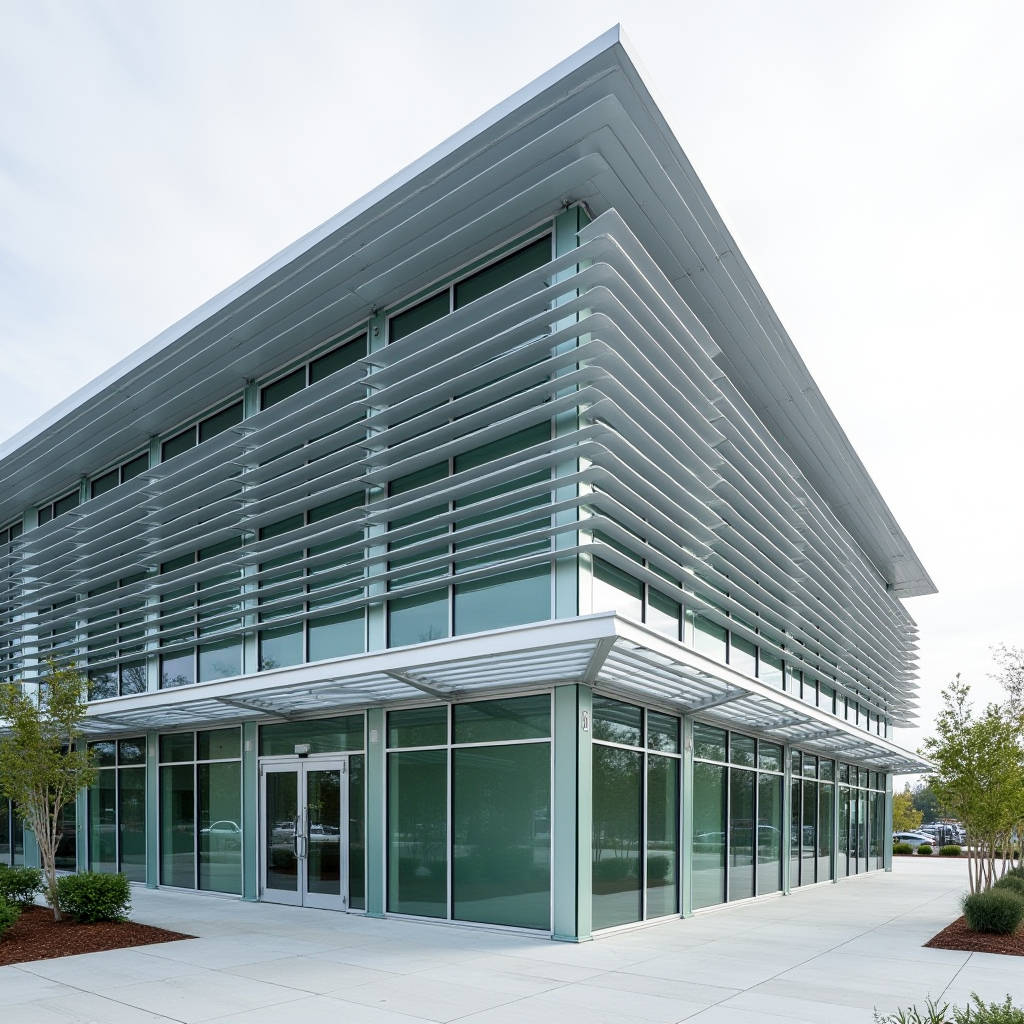
An Aluminium Louver Facade is far more than an architectural embellishment. For contractors and facade engineers, it represents a calculated interface between a building's internal environment and the external climate. Getting the specification right means reconciling structural wind loads, solar heat gain coefficients, drainage logic, and long-term maintenance access into a single, coherent envelope. The decisions made during the design development phase—blade profile geometry, bracket thermal isolation, finish chemistry—reverberate through the entire construction programme and the building's operational lifespan. This article examines the engineering logic that separates a facade that performs flawlessly for decades from one that becomes a liability. The focus stays on solid extruded or folded aluminium blades, typically ranging from 2.0 mm to 3.0 mm wall thickness, finished with high-performance PVDF or powder coatings, and supported by concealed fixings that respect thermal movement.
Engineering Rationale Behind Blade Geometry
Blade shape is not a styling exercise. Every profile—whether elliptical, rectangular, aerofoil, or Z-shaped—alters the airflow pattern, structural stiffness, and water deflection characteristics of the facade. An elliptical blade, for instance, offers a lower drag coefficient than a flat rectangular blade when wind flows perpendicular to the facade. This matters when the building sits in a coastal exposure category where wind speeds regularly exceed 40 m/s.
From a structural standpoint, the section modulus of the blade dictates its spanning capability between support brackets. A 200 mm wide extruded aluminium blade with a 2.5 mm wall thickness and internal stiffening ribs can typically span 1,500 mm to 1,800 mm between vertical mullions before deflection exceeds L/180 under serviceability wind loads. Engineers working on high-rise projects should request section property data from the extrusion supplier early in the design phase. Without this data, any span table is guesswork.
The blade's leading edge geometry also determines how rainwater behaves. A drip groove incorporated into the bottom edge of the extrusion prevents water from tracking back toward the building face. On projects where the louver facade functions as a rain screen, this detail is non-negotiable. Water that migrates behind the blade plane can saturate insulation, corrode backup wall components, and trigger interstitial condensation cycles that degrade the assembly from the inside out.
Wind Load Rationalisation for Louver Systems
Solid aluminium louvers behave differently under wind load than a sealed curtain wall. The open-joint nature of a louver facade means wind pressure acts on each blade individually while also partially pressurising the cavity behind. This creates a complex loading scenario that standard building codes do not always address explicitly.
ASCE 7 and EN 1991-1-4 provide frameworks for open lattice structures, but the engineer must decide whether to treat the louver array as a porous screen or as individual elements. The porous screen approach applies a net pressure coefficient to the entire facade area, reduced by a porosity factor. The individual element approach calculates wind force on each blade based on its projected area and shape factor. For most commercial projects, the porous screen method is conservative and simpler to document. However, for very large blades or widely spaced arrays, the individual element method captures local peak pressures that might govern bracket design.
A practical rule: when the open area ratio exceeds 40%, the internal pressure equalisation reduces net structural demand noticeably. At 50% open area, the net pressure coefficient can drop to 0.6–0.8 times the solid wall value, depending on blade angle. This is not a substitute for wind tunnel testing on complex geometries, but it provides a useful sanity check during schematic design.
| Blade Orientation | Typical Span (mm) | Open Area Ratio | Net Pressure Coefficient (Cp,net) | Applicable Wind Zone |
|---|---|---|---|---|
| Horizontal, 150 mm pitch | 1,200 – 1,600 | 35% – 45% | 0.70 – 0.85 | Low to Medium |
| Horizontal, 200 mm pitch | 1,500 – 2,000 | 45% – 55% | 0.55 – 0.70 | Medium |
| Vertical, 300 mm pitch | 2,000 – 2,800 | 50% – 60% | 0.50 – 0.65 | Medium to High |
| Elliptical, 150 mm pitch | 1,400 – 1,800 | 40% – 50% | 0.45 – 0.60 | High (Coastal) |
Thermal Performance and Solar Control Logic
The primary environmental function of an Aluminium Louver Facade is solar radiation management. The physics is straightforward: intercept direct beam radiation before it strikes the glazing or opaque wall behind it. The engineering challenge is predicting how much energy the louver actually blocks, because the answer depends on blade angle, surface reflectivity, and the sun's changing position throughout the day and year.
A fixed horizontal louver on a south-facing elevation (in the northern hemisphere) can block 70%–85% of peak summer solar gain when the blade projection and spacing are optimised for the local latitude. The calculation uses the profile angle of the sun at the summer solstice. For a building at 35° latitude, a blade projection of 300 mm with a 200 mm vertical spacing provides effective shading from approximately 10:00 to 14:00 solar time during June and July. Outside that window, low-angle sun penetrates the array.
The solar reflectance of the aluminium surface matters enormously. A standard PVDF coating in a medium-grey colour might have a Total Solar Reflectance (TSR) of 0.35–0.45. A high-reflectance PVDF formulation in a similar colour can push TSR above 0.65. The difference translates to a blade surface temperature reduction of 10°C–15°C under full sun. Cooler blades mean less long-wave radiation re-radiated toward the building interior, and less thermal expansion stress on the support system.
For projects pursuing LEED or BREEAM credits, the solar heat gain coefficient (SHGC) of the combined louver-plus-glazing assembly must be calculated. This is not simply the product of the louver's shading coefficient and the glass SHGC. The cavity between louver and window traps heat, and the louver blades themselves heat up and radiate. A detailed energy model using software like IES VE or DesignBuilder captures these effects. The investment in modelling pays back through right-sized HVAC equipment and reduced cooling energy over the building's life.
Finish Selection and Longevity in Aggressive Environments
The coating system on an aluminium louver facade does more than provide colour. It is the primary barrier against pitting corrosion, filiform corrosion, and UV degradation. The two dominant technologies are PVDF (polyvinylidene fluoride) liquid coatings and super-durable polyester powder coatings, each governed by different standards.
PVDF coatings meeting AAMA 2605 requirements use a 70% PVDF resin base with proprietary inorganic pigments. The total dry film thickness typically ranges from 30 to 45 microns across a three-coat system (primer, colour coat, clear coat). This chemistry has a track record spanning 40-plus years on architectural aluminium in Florida, Dubai, and Southeast Asia—environments that combine high UV, salt spray, and humidity. When a project specification demands a 20-year colour and gloss retention warranty, AAMA 2605-compliant PVDF is the default answer.
Super-durable polyester powders meeting AAMA 2604 or Qualicoat Class 2 standards offer a different value proposition. Applied electrostatically and cured at 180°C–200°C, these coatings achieve 60–80 microns in a single layer. They resist chalking better than standard polyester and cost less than PVDF. The trade-off: colour and gloss retention warranties typically cap at 10–15 years, and the colour palette for high-durability formulations is narrower than what PVDF can deliver.
Anodising deserves mention but requires caution. A 20-micron anodic layer (AA25 class per BS 3987) provides excellent hardness and a metallic appearance that coatings cannot replicate. However, anodised aluminium on a louver facade is vulnerable to surface staining from alkaline cleaning solutions and acid rain. The colour range is also limited to natural silver, bronze, and black tones. For coastal projects, anodising is generally not recommended unless the alloy is specifically selected for marine exposure and the anodic layer thickness is increased to 25 microns minimum.
Structural Support Systems and Thermal Bridging
The support framework behind an Aluminium Louver Facade determines whether the system performs as a true rain screen or becomes a thermal bridge that undermines the building's insulation strategy. The industry has largely converged on aluminium sub-frames fixed back to the primary structure through stainless steel brackets with thermal break pads.
The thermal break is a small component with an outsized impact. A 10 mm thick PVC or nylon isolator pad between the aluminium bracket and the steel embed plate can reduce point thermal transmittance by 60%–80% compared to a direct metal-to-metal connection. On a large facade with hundreds of brackets, the cumulative effect on the building's overall U-value is measurable. Projects targeting Passive House or net-zero energy standards must account for every bracket penetration.
Vertical mullion spacing is governed by the louver blade span capacity and the building's floor-to-floor dimensions. A typical arrangement uses 60 mm × 120 mm aluminium box sections at 1,500 mm centres, with the blades spanning horizontally between them. The mullions themselves are supported at each floor level by purpose-designed brackets that accommodate vertical live load deflection of the slab edge—typically ±15 mm to ±25 mm depending on the structural system. Slotted connections and oversized holes in the bracket allow the mullion to move relative to the primary structure without transferring load into the louver blades.
For projects where the louver facade extends continuously past floor slabs, expansion joints in the aluminium mullion system are essential. A 20 mm gap every 10–12 metres of continuous mullion length, bridged by a sliding sleeve, accommodates the differential thermal expansion between the aluminium frame and the concrete or steel primary structure. Skipping this detail leads to buckled mullions, popped fixings, and warranty claims.
Drainage, Ventilation, and Cavity Management
The cavity behind the louver blades is a working space. It must breathe to prevent moisture accumulation, drain any water that penetrates the blade plane, and allow air to circulate behind the blades to carry away heat. A poorly detailed cavity becomes a humid, stagnant zone where mould grows and fasteners corrode.
The minimum cavity depth recommended by most system manufacturers is 50 mm, but 75 mm to 100 mm is preferable. The deeper cavity reduces the risk of water bridging from the back of the louver blade to the insulation face, and it improves airflow. Ventilation openings at the top and bottom of the facade—typically 10 mm to 20 mm continuous slots—create a chimney effect that draws air through the cavity. On tall facades, intermediate vents every three to four floors prevent the chimney effect from becoming too strong and generating noise or pulling debris into the cavity.
At the base of the cavity, a continuous flashing with a drip edge directs water outward. The flashing should slope a minimum of 5 degrees toward the exterior and extend at least 50 mm beyond the face of the backup wall. Perforated closure profiles at the top and bottom of the louver array prevent birds and large insects from entering the cavity while maintaining airflow. These closures should be removable or hinged to allow periodic inspection and cleaning.
Procurement and Supply Chain Considerations
Specifying an Aluminium Louver Facade is one thing; procuring it on time and within budget is another. The extrusion lead time is the critical path item. Custom blade profiles require die manufacture, which adds four to six weeks before the first extrusion run. Standard profiles from a supplier's existing die library can ship in three to four weeks from order confirmation. For projects with tight programmes, the design team should query the extrusion catalogue early and avoid custom profiles unless the architectural intent absolutely demands them.
Finish application adds another layer of scheduling complexity. PVDF liquid coating requires a spray line with controlled temperature and humidity, and each coat needs curing time. A typical three-coat PVDF finish adds 10 to 14 working days to the production schedule. Powder coating is faster—five to seven working days—but the colour must be matched to an approved RAL or BS standard, and custom colours may require a minimum batch quantity that affects unit pricing.
Freight and packaging deserve attention. Louver blades are long, slender elements that are easily damaged in transit if not properly crated. Individual blade wrapping with foam interleaving, placed in purpose-built timber crates with internal bracing, is the standard for export shipments. The crates should be designed for forklift handling and containerised in a way that minimises movement during ocean transit. Suppliers with dedicated export packaging experience, such as Futeng®, understand that a scratched blade arriving on site represents a programme delay far more costly than the material itself.
Installation Tolerances and Quality Control
The visual success of an Aluminium Louver Facade lives or dies by installation tolerances. A 3 mm deviation in blade alignment is invisible at 20 metres but becomes a glaring defect at 5 metres. The specification must define acceptable tolerances for blade straightness, spacing consistency, and plane alignment, and the site QA/QC process must enforce them.
A practical tolerance framework: individual blade straightness within 1 mm per metre of length, measured with a straight edge; blade-to-blade spacing variation not exceeding ±2 mm across any 10-metre run; overall facade plane deviation within ±5 mm over a 3-metre straight edge, and within ±10 mm over any 10-metre length. These numbers align with the AAMA TIR-A9 guidelines for metal cladding installation and are achievable with skilled labour using laser alignment tools.
Bracket positioning is the foundation of alignment. The primary structure's as-built geometry rarely matches the design model perfectly. A site survey using total station equipment, conducted before bracket fabrication, captures the actual slab edge positions. The bracket design can then incorporate slotted holes or shim packs to absorb the surveyed deviations. This step adds cost and time to the pre-installation phase but eliminates the field modifications and compromised aesthetics that result from trying to force a theoretical bracket layout onto an imperfect structure.
Maintenance Access and Lifecycle Planning
A louver facade is not maintenance-free, but it should be maintenance-friendly. The design must anticipate how the building operator will clean the blades, inspect fixings, and replace damaged components 10 or 20 years after handover. Access is the dominant constraint. On a high-rise, every maintenance activity requires either a building maintenance unit (BMU) or rope access technicians, both of which cost money and require scheduling.
Blade profiles with smooth, continuous surfaces clean more easily than profiles with sharp corners, grooves, or perforations. A simple elliptical or rectangular blade can be wiped down from a BMU cradle with a soft brush and mild detergent. Textured finishes and woodgrain effects, while visually appealing, trap dirt in the grain pattern and require more frequent cleaning to maintain appearance.
Fixings should be accessible from the front face wherever possible. Concealed clip systems that require blade removal for bracket inspection add labour cost to every maintenance cycle. A visible stainless steel screw, properly detailed with a colour-matched cap, is often the more practical choice. The specification should call out A4 (316) grade stainless steel for all external fixings in coastal or industrial environments, as A2 (304) grade can suffer crevice corrosion in chloride-rich atmospheres.
Lifecycle cost analysis, even a simplified one, reveals that the initial material cost of the louver system is a fraction of the total cost of ownership. Cleaning, inspection, and recoating over a 30-year service life can equal or exceed the original installation cost. A PVDF finish that costs 15%–20% more upfront than a standard powder coat may eliminate the need for a mid-life recoating cycle, delivering a lower net present value over the building's life. This is the conversation that specification writers need to have with cost consultants before value engineering strips out the durability provisions.
An Aluminium Louver Facade that performs over decades is the product of integrated engineering thinking. The blade geometry, wind load path, thermal isolation strategy, coating chemistry, drainage design, and maintenance access plan are not independent decisions. They form a chain, and the chain is only as strong as its weakest link. Contractors who invest in detailed shop drawings, third-party performance testing, and experienced installation crews will deliver a facade that meets the architect's vision without compromising the building's physics. The projects that cut corners on cavity depth, bracket thermal breaks, or coating specification will generate callbacks, warranty claims, and disappointed clients. The difference between the two outcomes is not mysterious—it is engineered.